
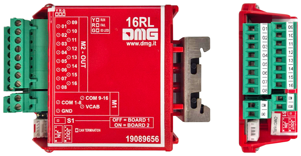
16 Relays control board
The 16RL board is used to interface the DMG controller with non-serial devices/products.
These devices may include:
• 1 wire per floor position indicator
• Gray code indicator
• 9-segment indicator
• 1 wire per floor HYD (for managing hydraulic power units)
• Present signal
• Floor lighting
The display normally shows the car position (absolute floor; when at the lowest floor = Floor 0), except for the 9-segment output, which depends on the characters programmed for each floor.
These outputs are not displayed, when the elevator is operating in the following modes:
• Reset
• Inspection
• Temporary operation
• Emergency operation
1 wire per floor position indicator
The output corresponding to the elevator car’s absolute position is selected (the reference is the absolute floor level shown on the display).
The active line is always just one.
The system supports a maximum of 16 floors.

Up to 14 floors, direction arrows are also supported.
| OUT 01 | Floor 0 | OUT 09 | Floor 8 |
| OUT 02 | Floor 1 | OUT 10 | Floor 9 |
| OUT 03 | Floor 2 | OUT 11 | Floor 10 |
| OUT 04 | Floor 3 | OUT 12 | Floor 11 |
| OUT 05 | Floor 4 | OUT 13 | Floor 12 |
| OUT 06 | Floor 5 | OUT 14 | Floor 13 |
| OUT 07 | Floor 6 | OUT 15 | Floor 14 |
| OUT 08 | Floor 7 | OUT 16 | Floor 15 |
Gray code indicator
Transmits the car’s absolute position in Gray code.
• OUT1-OUT5: Output type A (floor 0=-3)
• OUT6: Lift in Inspection mode (since software version 3.2.1)
• OUT7 : Down direction arrow
• OUT8 : Up direction arrow
• OUT9-OUT13 : Output type B (floor 0=0)
• OUT14 : Lift not available
• OUT15 : Down direction arrow
• OUT16 : Up direction arrow
| OUT 01 | G0 | OUT 09 | G0B |
| OUT 02 | G1A | OUT 10 | G1B |
| OUT 03 | G2A | OUT 11 | G2B |
| OUT 04 | G3A | OUT 12 | G3B |
| OUT 05 | G4A | OUT 13 | G4B |
| OUT 06 | OUT 14 |  | |
| OUT 07 | | OUT 15 | |
| OUT 08 | | OUT 16 | |
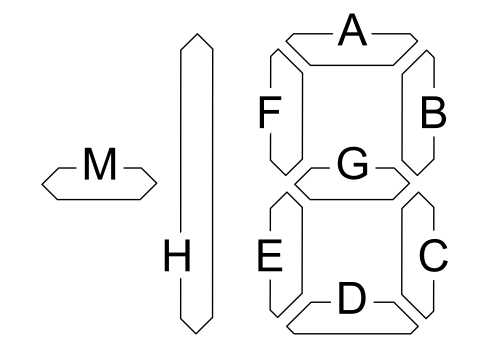
9-segment indicator
A position signal is transmitted in binary format (up to 32 floors) and via a 9-segment display (see image below). The values shown on the 9-segment reflect the configuration set in the control panel.
In addition, it is possible to drive a binary display using outputs Out 16 to Out 12 (see table below); in this case, the output corresponds to the panel’s absolute floor and cannot be modified (as in the case of GRAY code signaling).
| OUT 01 | Seg A | OUT 09 | Seg M |
| OUT 02 | Seg B | OUT 10 | |
| OUT 03 | Seg C | OUT 11 | |
| OUT 04 | Seg D | OUT 12 | BIN 0 |
| OUT 05 | Seg E | OUT 13 | BIN 1 |
| OUT 06 | Seg F | OUT 14 | BIN 2 |
| OUT 07 | Seg G | OUT 15 | BIN 3 |
| OUT 08 | Seg H | OUT 16 | BIN 4 |
| Floor | OUT 16 | OUT 15 | OUT 14 | OUT 13 | OUT 12 |
| 31 | 1 | 1 | 1 | 1 | 1 |
| 30 | 1 | 1 | 1 | 1 | 0 |
| 29 | 1 | 1 | 1 | 0 | 1 |
| 28 | 1 | 1 | 1 | 0 | 0 |
| 27 | 1 | 1 | 0 | 1 | 1 |
| 26 | 1 | 1 | 0 | 1 | 0 |
| 25 | 1 | 1 | 0 | 0 | 1 |
| 24 | 1 | 1 | 0 | 0 | 0 |
| 23 | 1 | 0 | 1 | 1 | 1 |
| 22 | 1 | 0 | 1 | 1 | 0 |
| 21 | 1 | 0 | 1 | 0 | 1 |
| 20 | 1 | 0 | 1 | 0 | 0 |
| 19 | 1 | 0 | 0 | 1 | 1 |
| 18 | 1 | 0 | 0 | 1 | 0 |
| 17 | 1 | 0 | 0 | 0 | 1 |
| 16 | 1 | 0 | 0 | 0 | 0 |
| 15 | 0 | 1 | 1 | 1 | 1 |
| 14 | 0 | 1 | 1 | 1 | 0 |
| 13 | 0 | 1 | 1 | 0 | 1 |
| 12 | 0 | 1 | 1 | 0 | 0 |
| 11 | 0 | 1 | 0 | 1 | 1 |
| 10 | 0 | 1 | 0 | 1 | 0 |
| 9 | 0 | 1 | 0 | 0 | 1 |
| 8 | 0 | 1 | 0 | 0 | 0 |
| 7 | 0 | 0 | 1 | 1 | 1 |
| 6 | 0 | 0 | 1 | 1 | 0 |
| 5 | 0 | 0 | 1 | 0 | 1 |
| 4 | 0 | 0 | 1 | 0 | 0 |
| 3 | 0 | 0 | 0 | 1 | 1 |
| 2 | 0 | 0 | 0 | 1 | 0 |
| 1 | 0 | 0 | 0 | 1 | 1 |
| 0 | 0 | 0 | 0 | 0 | 0 |
1 wire per floor HYD
System for managing Hydro electronic control units (e.g., i-Valve). The first eight outputs operate on a one-wire-per-floor basis (Hydro systems typically do not exceed eight stops, making them compatible with display driving).
It provides for the use of a 16 I/O board with the following features (see the table on the right.)
| OUT 01 | Floor 0 | OUT 09 | (*) |
| OUT 02 | Floor 1 | OUT 10 | (*) |
| OUT 03 | Floor 2 | OUT 11 | (*) |
| OUT 04 | Floor 3 | OUT 12 | (*) |
| OUT 05 | Floor 4 | OUT 13 | (*) |
| OUT 06 | Floor 5 | OUT 14 | (*) |
| OUT 07 | Floor 6 | OUT 15 | (*) |
| OUT 08 | Floor 7 | OUT 16 | (*) |
(*) Control signals for the electronic control unit valves (up, down, speed, etc.).
Present signal
The output corresponding to the elevator car’s absolute position is selected, but only with the car stopped at a floor.
The signal is activated when the retractable guide shoe command is released.
The system supports a maximum of 16 floors.
Up to 14 floors, direction arrows are also supported.
| OUT 01 | Floor 0 | OUT 09 | Floor 8 |
| OUT 02 | Floor 1 | OUT 10 | Floor 9 |
| OUT 03 | Floor 2 | OUT 11 | Floor 10 |
| OUT 04 | Floor 3 | OUT 12 | Floor 11 |
| OUT 05 | Floor 4 | OUT 13 | Floor 12 |
| OUT 06 | Floor 5 | OUT 14 | Floor 13 |
| OUT 07 | Floor 6 | OUT 15 | Floor 14 |
| OUT 08 | Floor 7 | OUT 16 | Floor 15 |
Light at floor
Once the elevator car reaches a floor and stops, the controller activates the output corresponding to the elevator car’s absolute position for 3 seconds.
The system supports a maximum of 16 floors.
The option to be provided is:
• Q40.FNLCP – Floor light function => fixed part
• Q40.FNLCP_V – Floor light function (variable) => provide one for each floor.
Up to 14 floors, direction arrows are also supported.
| OUT 01 | Floor 0 | OUT 09 | Floor 8 |
| OUT 02 | Floor 1 | OUT 10 | Floor 9 |
| OUT 03 | Floor 2 | OUT 11 | Floor 10 |
| OUT 04 | Floor 3 | OUT 12 | Floor 11 |
| OUT 05 | Floor 4 | OUT 13 | Floor 12 |
| OUT 06 | Floor 5 | OUT 14 | Floor 13 |
| OUT 07 | Floor 6 | OUT 15 | Floor 14 |
| OUT 08 | Floor 7 | OUT 16 | Floor 15 |
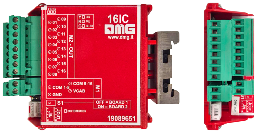
16 IC control board
The 16IC board is used to integrate the elevator top of cabin signals in the case of a 4.1 screw terminal controller.
Power and the CAN-BUS communication are supplied to the board via a 5-pin JST 2 mm-pitch cable connected between the board’s JIN connector and the J26 connector on the main board. The JOUT connector is used to cascade subsequent expansion boards, such as 16IO boards (for calls) and any 16RL boards (using a “short” cable, as the boards are connected in series). The connection order is irrelevant since communication between boards is serial, and each board is identified by its type and the S1 DIP switch on the board.
The S1 DIP switch is used to identify the board as first (BOARD 1) or second (BOARD 2). For the signals required by a screw terminal version controller, the 16IC board must be BOARD 1 (DIP S1 in the OFF position).
The assignment of signals to the corresponding screw terminals is shown in the table below.
For output signals (GND closure), it is permitted to drive 24 V DC relays or outputs and LEDs (maximum load: 24 V DC, 20 mA).
I/O (Inputs and Outputs)
| Screw terminal | Type | Signal | Description |
|---|---|---|---|
| 01 | Input | FAI | Counting sensor |
| 02 | Input | FAS | Counting sensor |
| 03 | Input | AGb | Low-phase shifter |
| 04 | Input | AGh | High-phase shifter |
| 05 | Input | REV1 | Top of cabin inspection button |
| 06 | Input | RED1 | Top of cabin DOWN inspection button |
| 07 | Input | REM1 | Top of cabin UP inspection button |
| 08 | Input | CPOM | Firefighter’s key in the cabin |
| 09 | Input | PCA | Cabin priority key |
| 10 | Output | LOW_B | Battery low indication |
| 11 | Output | OVL | Elevator cabin overload indication |
| 12 | Output | VHS | Out of service indication |
| 13 | Output | GNG_D | Downward gong signal (Occupied for non-call operations) |
| 14 | Output | GNG_M | Upward gong signal (Door opening for non-call operations) |
| 15 | Output | FLD | Downward arrow signal |
| 16 | Output | FLM | Upward arrow signal |