(v 1.2)
Safety and usage cautions
Before installing our products, we recommend you to consult the section about safety and usage cautions at the link below

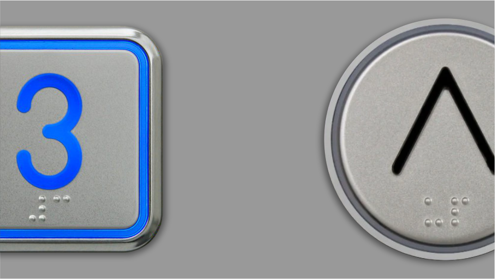
B7 S Tiger – Round shape
Cut-out (back mounting)
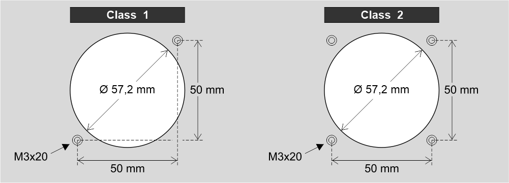

Back view – stud side (studs M3x20)
Cut-out (frontal mounting)
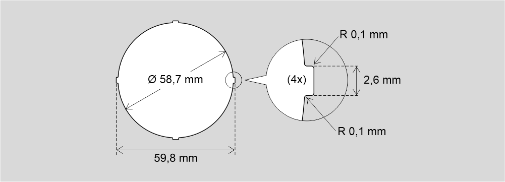
Note: There are 4 anti-rotation points
Assembling (Back mounting)
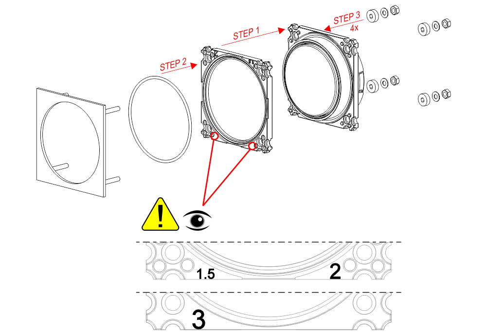
Assembling (Frontal mounting)
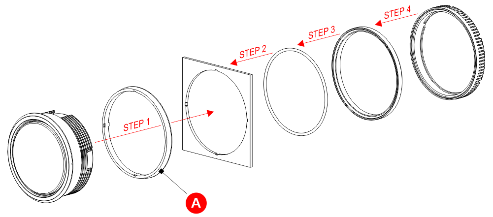
A) Present ONLY with the main floor push-button.
Wirings
Screw terminal version
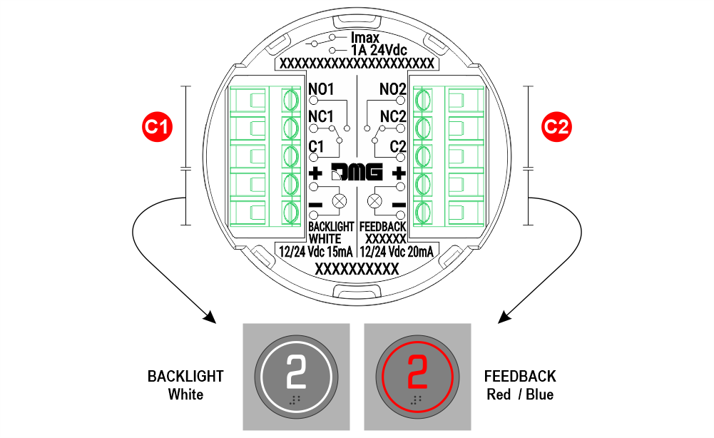
C1) First contact
C2) Second contact (e.g.: Alarm button)
JST connector version for Pitagora 4.0 prewiring – Call butttons
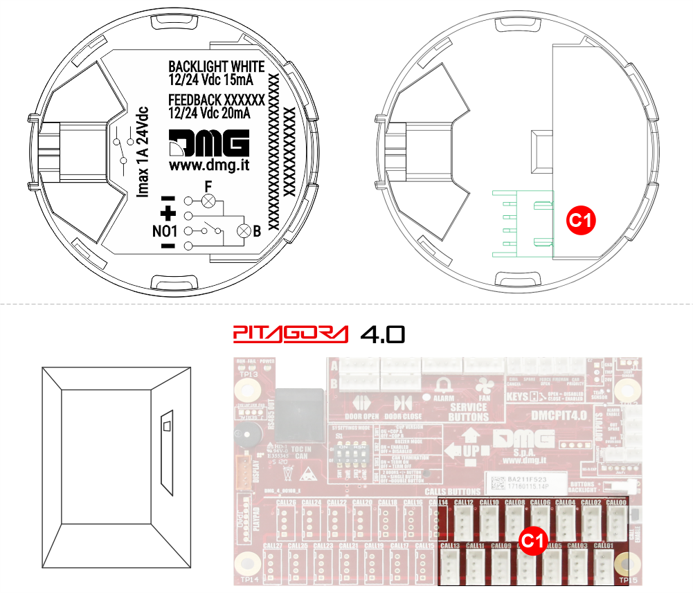
C1) 4-pin JST connector for connection to the DMCPIT board in the cabin.
JST connector version for Pitagora 4.0 prewiring – Alarm buttton
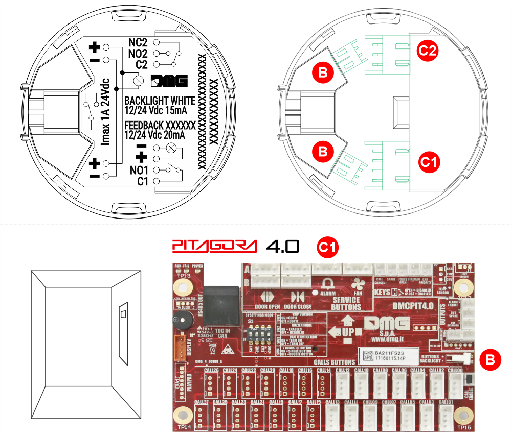
B) 2-pin JST connector for backlight connection to the DMCPIT board (2-pin AMP connector) in the cabin
C1) 4-pin JST connector for connection to the DMCPIT board in the cabin.
C2) 3-pin JST connector (dry contact) for connection to third-party telephony systems.
B7 Q Maxxi – Square shape
Cut-out

Mounting
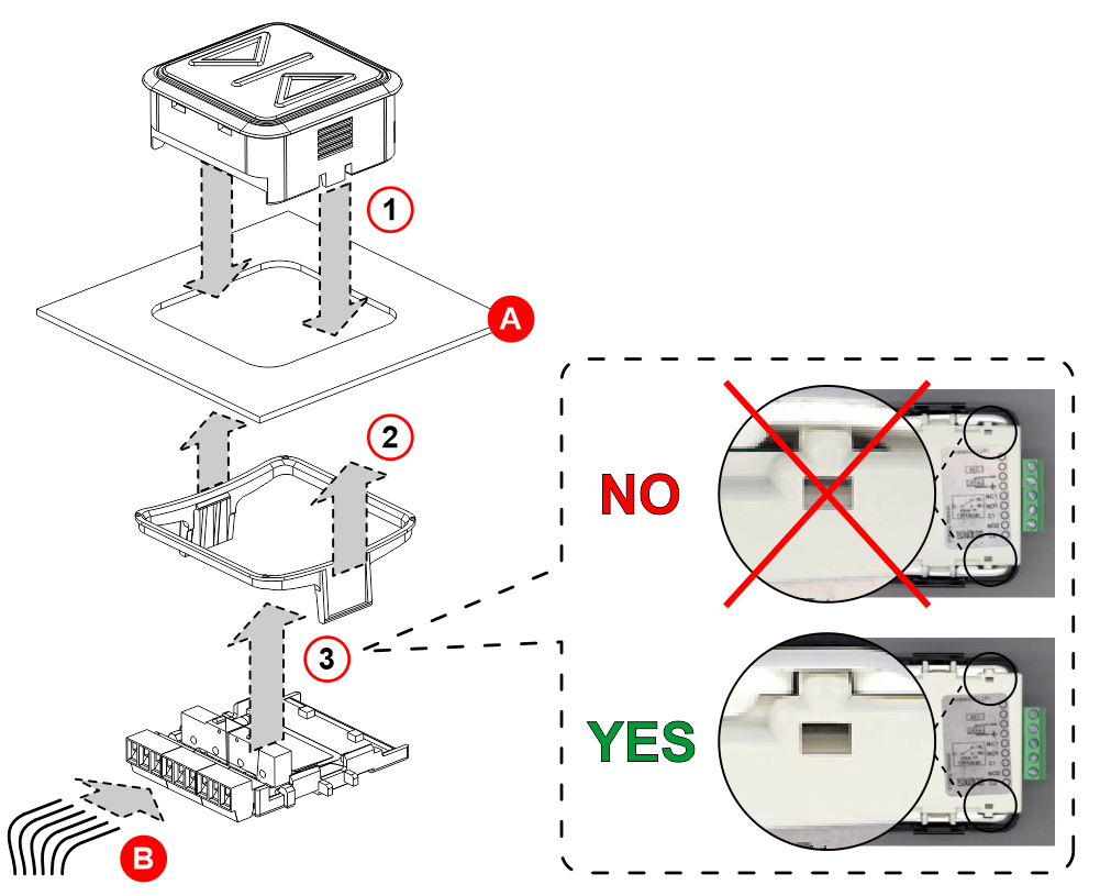
A) – Faceplate
B) – Wiring
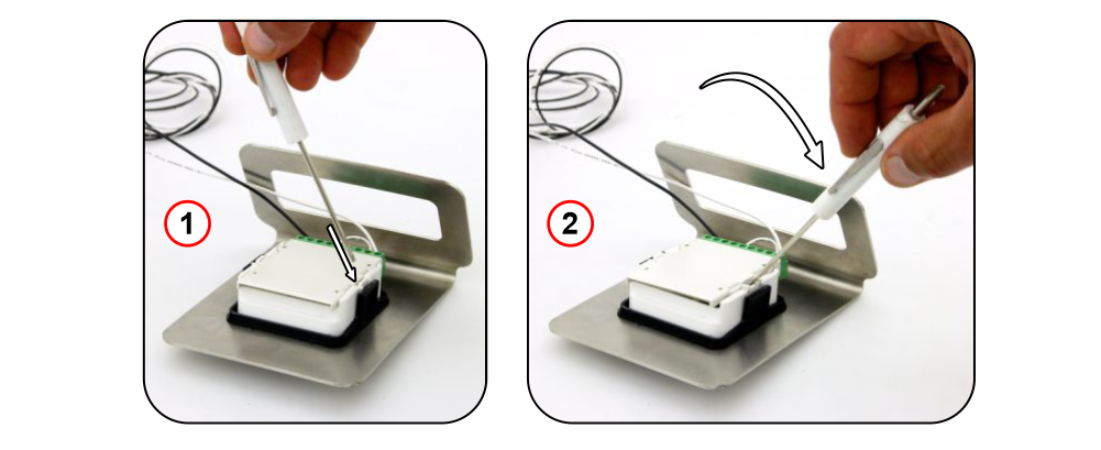
Dismantling
Mounting of B7 IP54 version, EN81-71 class 1
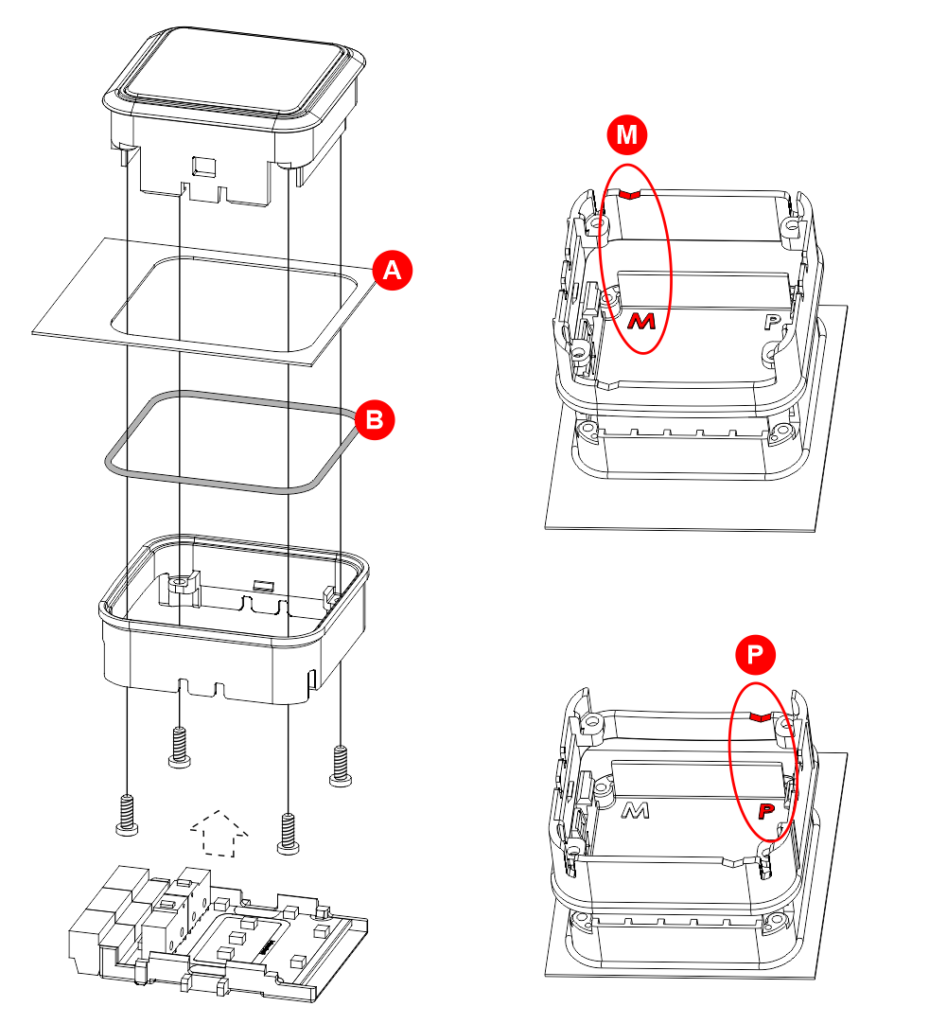
A) – Faceplate
B) – O-Ring
M) – Screw terminal version (back view)
P) – Prewired version (back view)
Main floor button
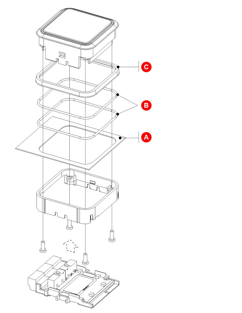
A) – Faceplate
B) – O-Ring
C) – Main floor bezel
Download
| Reference | Version | Link |
|---|---|---|
| 1.0 | Download PDF (English) | |
| Main floor version | 1.1 | Download PDF (English) |
| Round version | 1.2 (current version) | Download PDF (English) |