(v 1.4)
Safety and usage cautions
Before installing our products, we recommend you to consult the section about safety and usage cautions at the link below

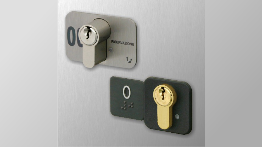
Mounting of services key (variant 1/2/3/4)
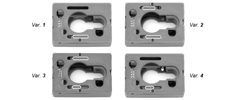
Plate mounted component
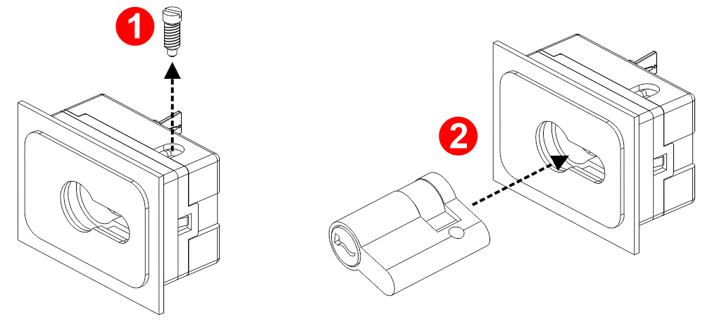
[ 1 ] – Remove the locking screw.
[ 2 ] – Insert the cylinder.
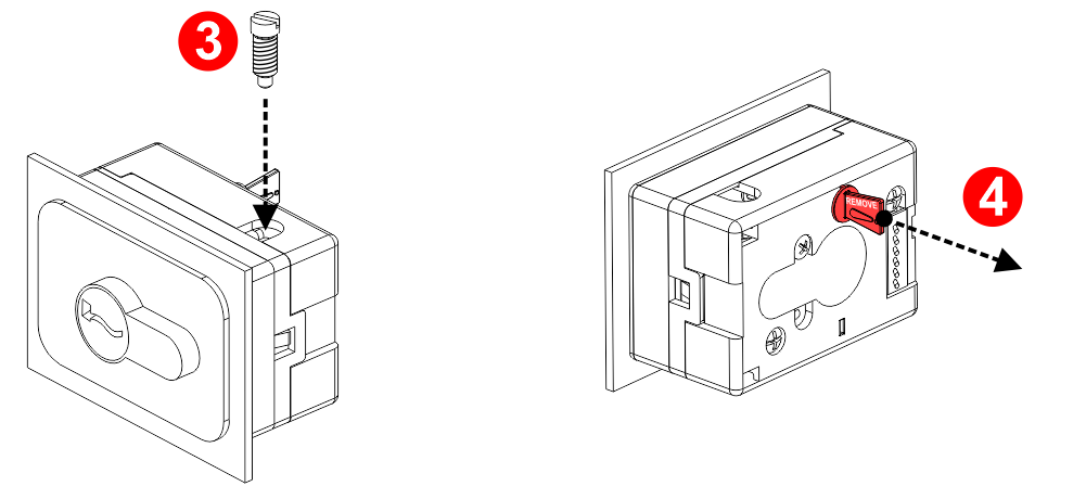
[ 3 ] – Insert the locking screw.
[ 4 ] – Remove the security lock.
Spare component (not plate mounted)
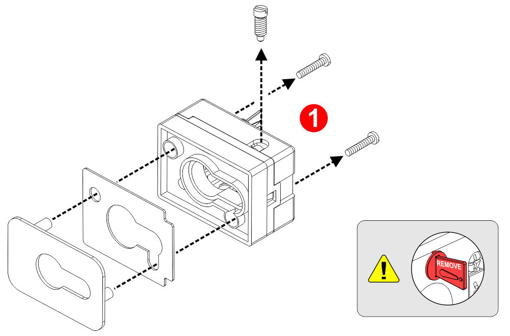
[ 1 ] – Disassemble the components.
Attention: don’t remove now the security lock.
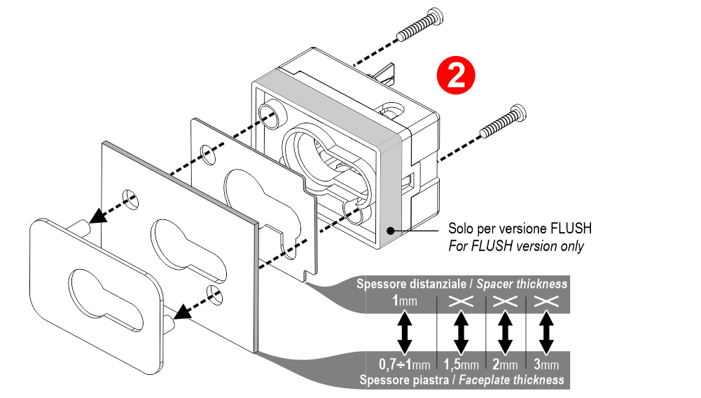
[ 2 ] – Assemble the components to the plate as shown in the picture.
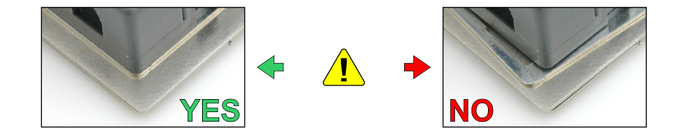
Be careful to the spacer alignment.
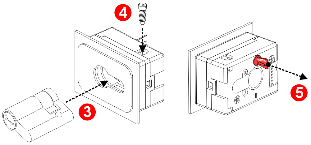
[ 3 ] – Insert the cylinder.
[ 4 ] – Insert the locking screw.
[ 5 ] – Remove the security lock.
Mounting of calls key (variant 5)
Plate mounted component
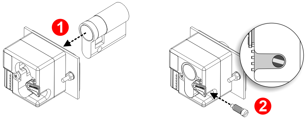
[ 1 ] – Insert the cylinder.
[ 2 ] – Insert the locking screw.

[ 3 ] – Remove the security lock.
Spare component (not plate mounted)
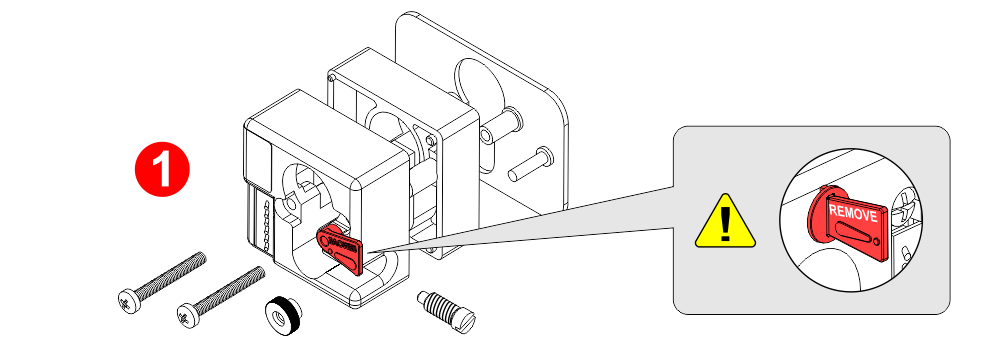
[ 1 ] – Disassemble the components.
Attention: don’t remove now the security lock.
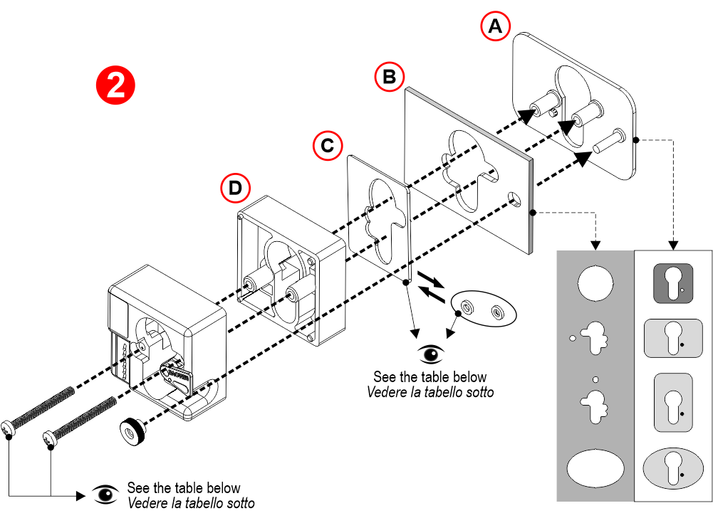
[ 2 ] – Assemble the components to the plate as shown in the picture.
A) – Aesthetic plate
B) – Cut-out
C) – Spacer
D) – Flush version only
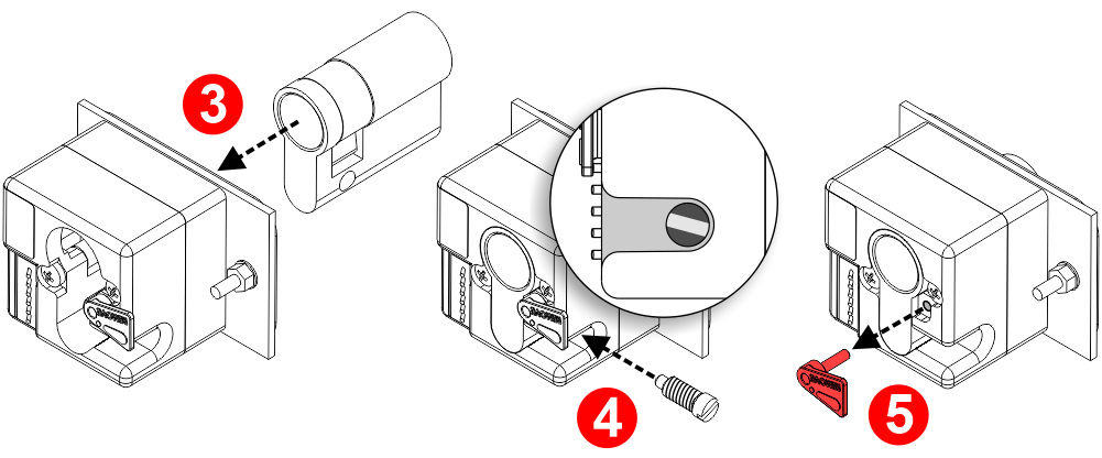
[ 3 ] – Insert the cylinder.
[ 4 ] – Insert the locking screw.
[ 5 ] – Remove the security lock.
Cylinder replacement
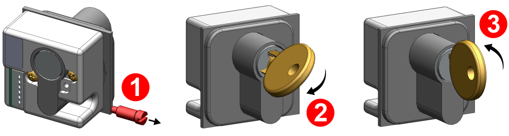
[ 1 ] – Remove the locking screw.
[ 2 ] – Gently turn the key in the sense of activation and pull out the cylinder about 5mm until it stops.
[ 3 ] – Release the key to position 0, then completely pull out the cylinder.
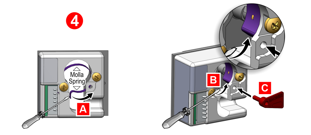
[ 4 ] – Using a screwdriver, restore the spring in the correct position (A+B) and simultaneously insert the spring security lock (C) or any 2mm diameter cylindrical element.
Now you can insert the new cylinder.
Download
| Reference | Version | Link |
|---|---|---|
| 1.4 (current version) | Download PDF (English) | |