
Overview
The Pitagora 4.0 System offers two different wiring solutions to connect the landing operating panel to the controller:
Serial Wiring
Based on a single serial connection line, interspersed with shaft units (BDU), this solution is most suitable for new installations and complete modernizations, especially for buildings with a higher number of floors, typically above 6-8.
Parallel Wiring
Based on a parallel board in the control panel with direct and parallel connections to each floor of the system. This solution is typically adopted in partial modernizations of residential installations, especially when it is required to keep the existing pushbuttons. It can also be advantageous for new installations with a limited number of floors.
Serial wiring
The serial wiring solution uses a CAN BUS signal to manage all signals between the controller and the floors, both for call buttons and for displays and accessories. The basic schematic includes:
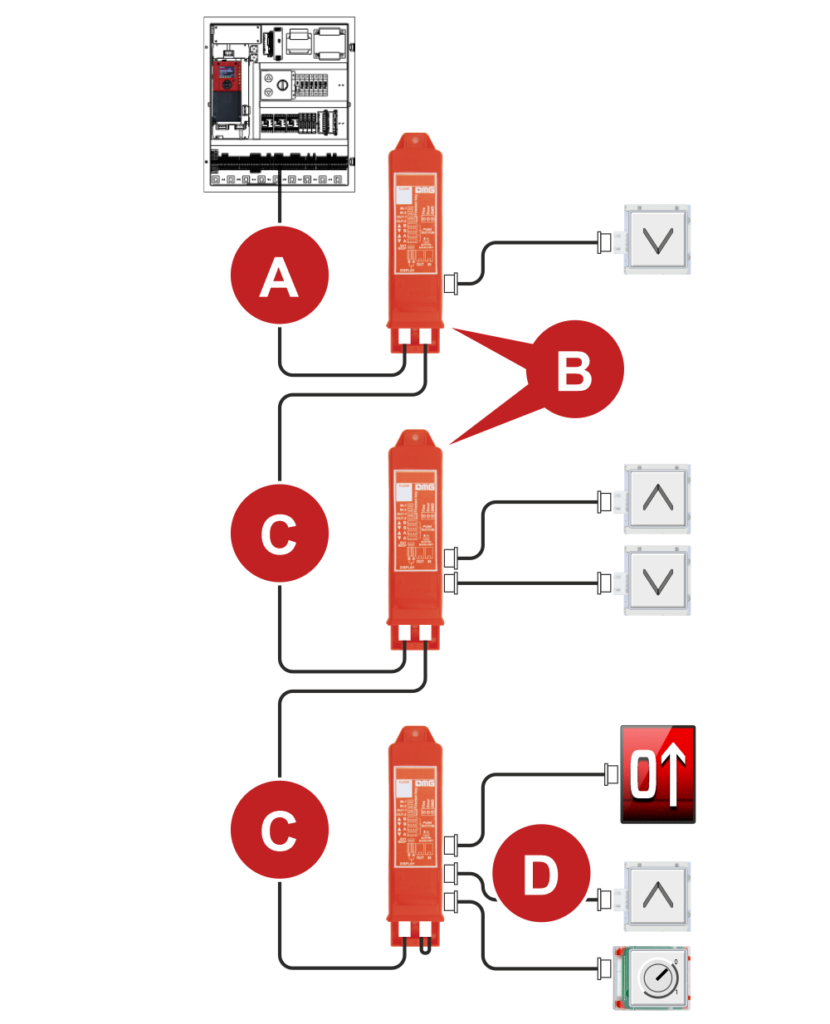
- A 4p miniwago cable (10m, 15m, or 20m) between the control panel and the first shaft BDU.
For each floor:
- A shaft BDU for each floor of the system
- A 4p “BDU line” minifit cable of 3,5m / 5m / 10m (depending on floor height) for connection to the BDU on the next floor.
- A set of cables between the BDU and the landing pushbutton / floor indicator
Serial line connection
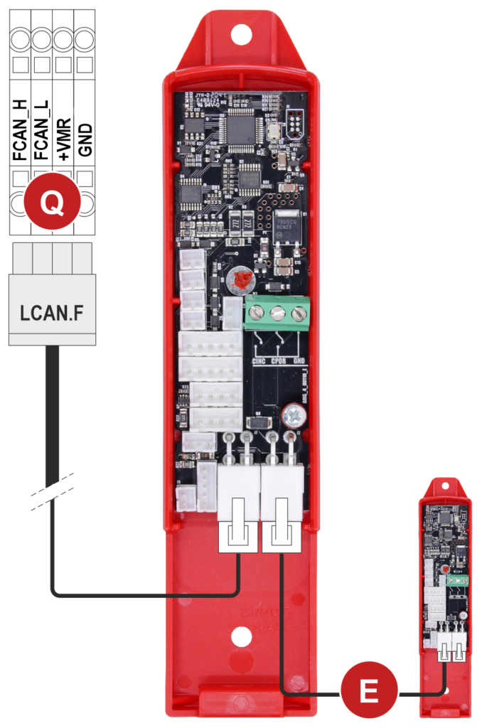
Q) Controller
E) Connection to the next BDU
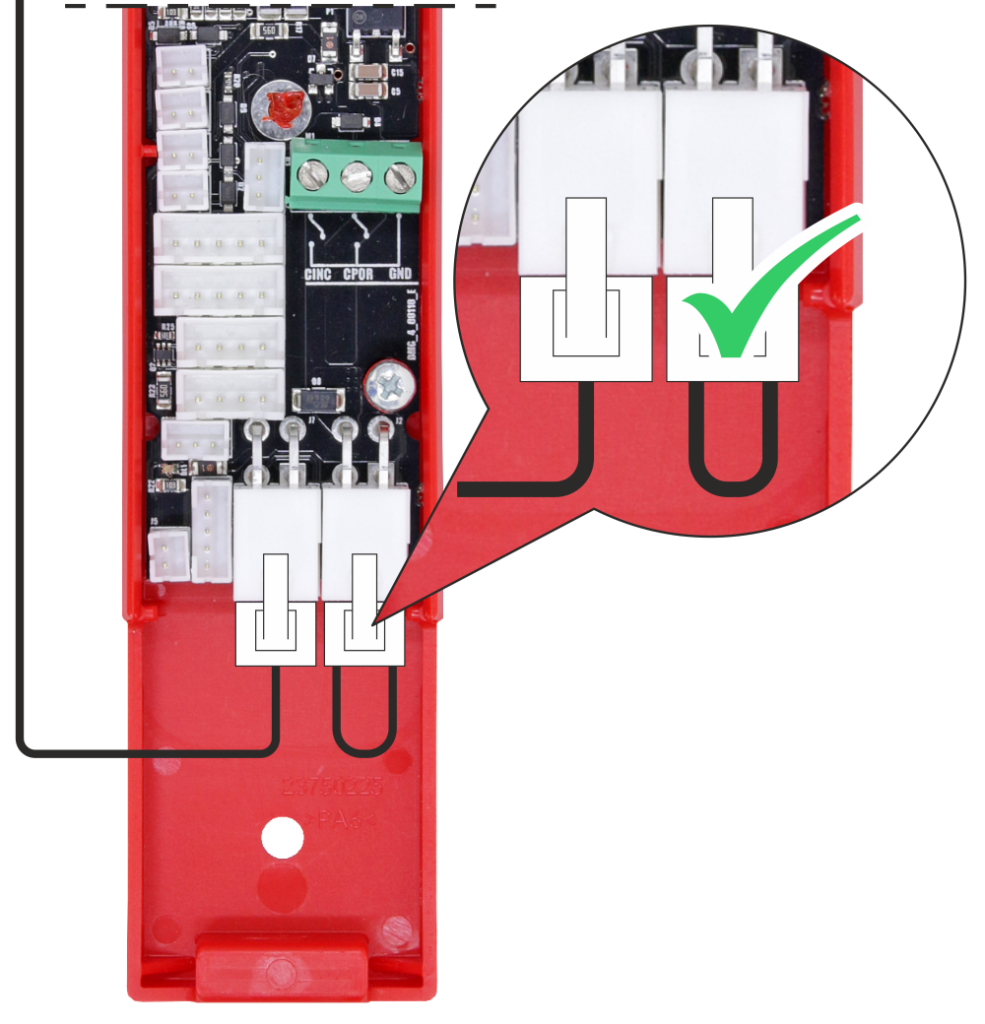

The last BDU of the serial line must be bridged as shown in the figure.
Connecting the BDU serial interface to the call push-buttons
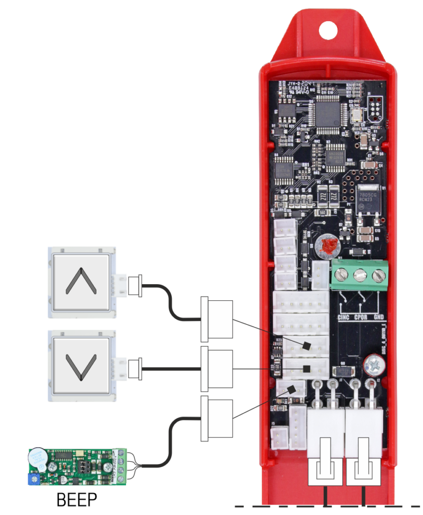
The additional optional BEEP interface board is required in the case of call button contact modules that do not have an integrated BEEP.
Connecting the BDU serial interface to the position indicator
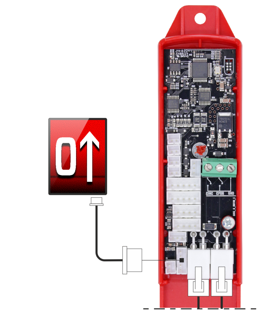
The BDU module can be connected to the DMG displays of the following series
- Banksy
- Raffaello
- Giotto
Connecting the BDU serial interface to the key contacts
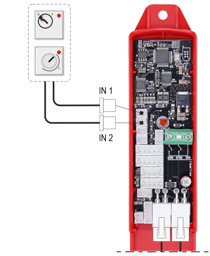
The two inputs IN1 and IN2 are programmable inputs from the controller and are typically used for key switch contacts associated with different functions.
Input IN1
- Call Disable (Default): Open contact = call enabled; closed contact = call disabled.
- Priority LOP function.
- Penthouse+Guest function: N.O. key switch contact.
Input IN2
- Out-of-Service Key Input (Default): This input can be used as a replacement for the HS signal on the controller terminal block.
Connecting the BDU serial interface to the signals
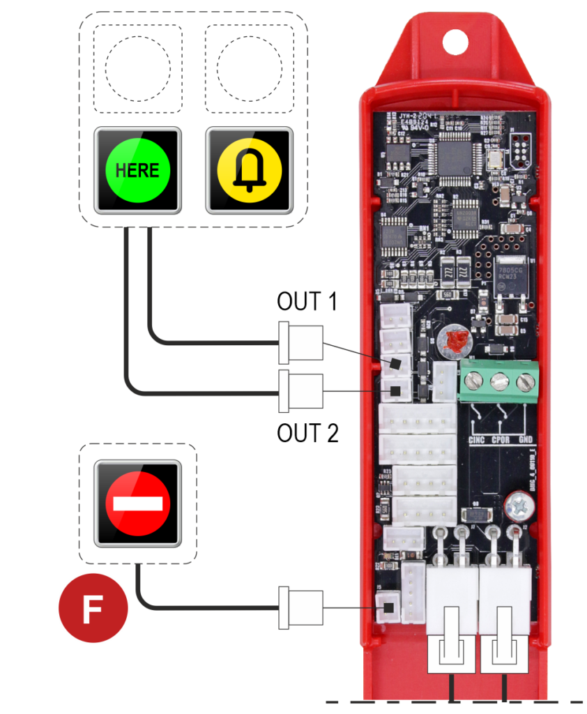
The two outputs OUT-1 and OUT-2 are programmable outputs for signals, and they are associated with preset sets of parallel outputs.
(See the table below)
F) The “Out of Service” signal is not programmable and is not available in the case of a duplex-light system.
| OUT 1 | OUT 2 |
|---|---|
| Present | Out os service |
| Up arrow | Down arrow |
| Present | Incoming |
| Present | 3W display (The wiring on the BDU for the 3-Wire Display is connected to the Display output with a 5-pin connector.) |
Connecting the BDU serial interface to the Firefighters key
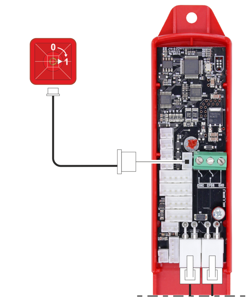
Connecting the BDU serial interface to the Sensors
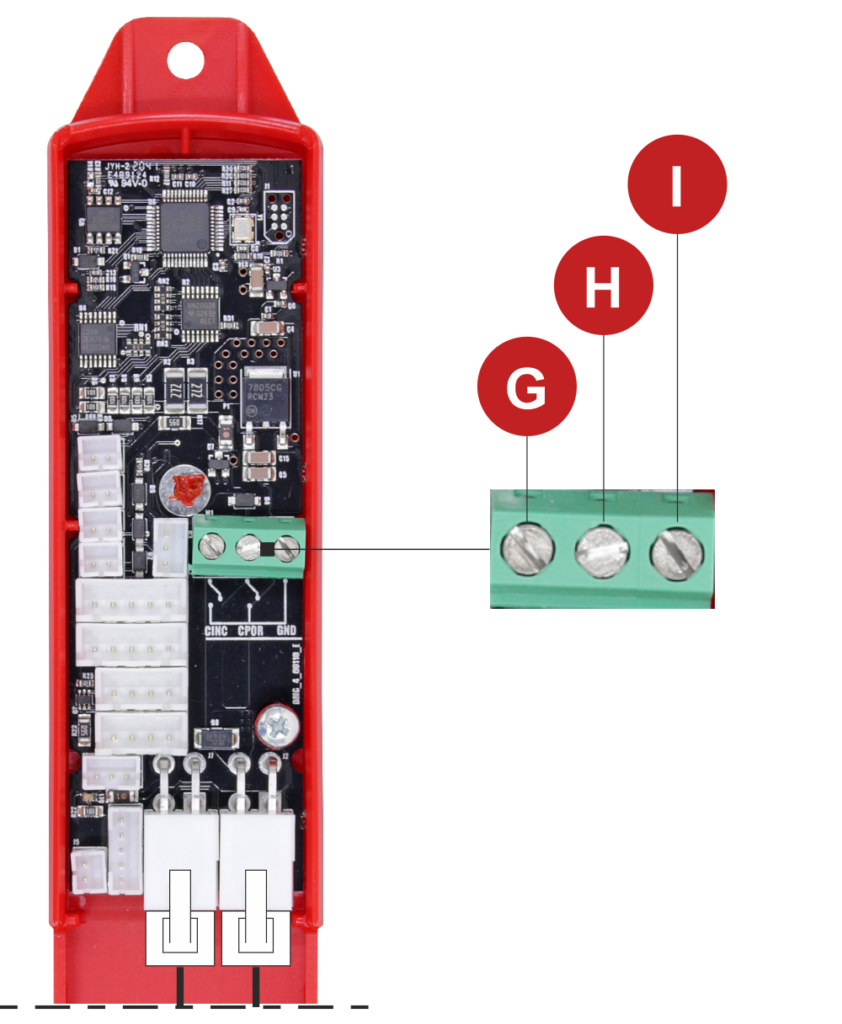
G) Fire contact
H) Doors contact
I) GND
BDU Addressing Procedure

The BDUs are pre-addressed at the factory;
however, if they are not addressed (e.g. replacement), the floor call button will start flashing.
1) Set the lift in normal operation
Menu Configuration >>> Temporary operations >>> NO
2) Move the car to the floor with the BDU to be addressed.
3) Press the floor call button for at least 5 seconds and check that, upon release, the button is no longer flashing.
BDU Reset

The BDUs are pre-addressed at the factory;
however, if they are not addressed (e.g. replacement), the floor call button will start flashing.
1) Set the lift in temporary operation
Menu Configuration >>> Temporary operations >>> YES
2) Press the floor call button for at least 10 seconds.
Parallel wiring with plug-in connectors interface
This solution uses parallel signals for each floor, following the “1 wire per floor” logic, to manage call requests. A 3-wire serial communication is instead retained to operate any floor displays.
The basic schematic provides that each landing push button panel is independently connected to the controller via RJ45 telephone cables.
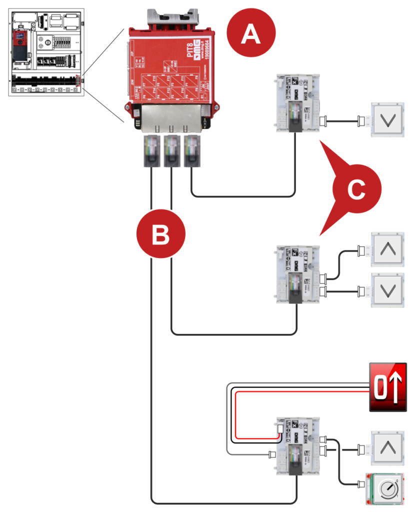
- Q40.PIT8 Interface Board
Manages up to 8 floors and is offered as an optional module installed inside the controller, mounted on a DIN rail and powered directly by the main board.
For systems with more than 8 floors, an additional Q40.PIT8 board must be added, which will receive power from the first board - RJ45 Connection Cables
- Interface Board for connecting buttons, indicators, keys, and displays.
CSITLOPV30 (without integrated beep) – for button families that already integrate the beep within the contact module.
CSITLOPV3B (with integrated beep) – for button families that do not include a built-in beep within the contact module.
Connecting the controller to each floor
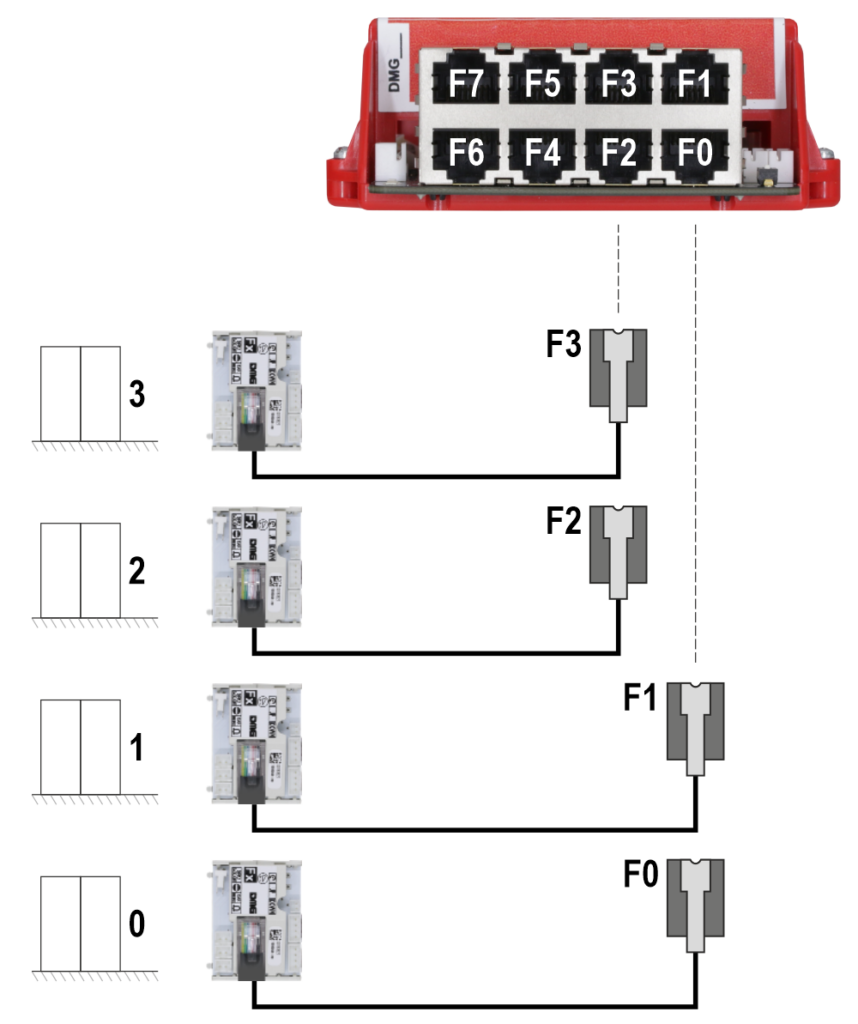
Using 8-pin RJ45 telephone cables, connect the Q40.PIT8 interface board located inside the controller to each CSTILOPV30 interface installed on each floor, for up to a maximum of 8 floors.
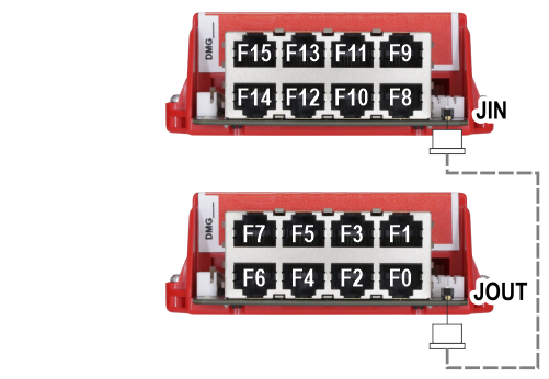
For more than 8 floors, add and connect an additional Q40.PIT8 interface board as shown in the image.
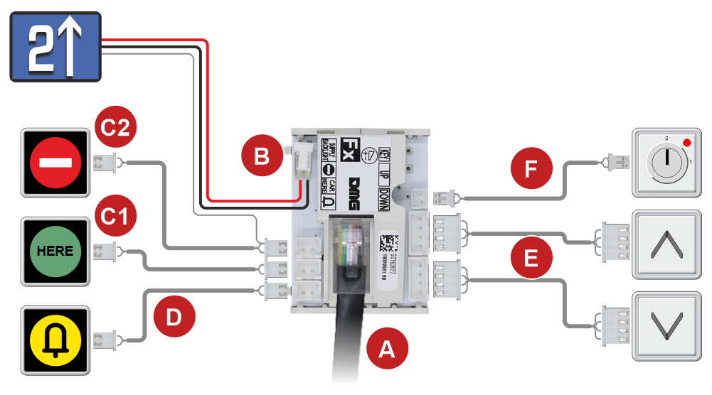
- RJ45 telephone cable input from the Q40.PIT8 interface board in the controller.
- Display power supply
- Programmable signal outputs – OUT-1 (C1) / OUT-2 (C2)
- Signal output (S12)
- Call buttons (Up and Down)
- Key input IN-1 (isolated for each floor)
Parallel wiring with terminal block interface
This quick solution is suitable for connecting existing push-button panels with screw terminals to the Pitagora system.
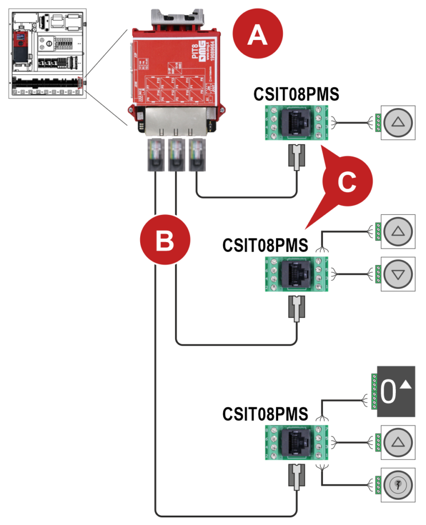
- Q40.PIT8 Interface Board
Manages up to 8 floors and is offered as an optional module installed inside the controller, mounted on a DIN rail and powered directly by the main board.
For systems with more than 8 floors, an additional Q40.PIT8 board must be added, which will receive power from the first board - RJ45 Connection Cables
- CSIT08PMS – Terminal block Interface Board for connecting buttons, indicators, keys, and displays.
Terminal Block Interface description (CSIT08PMS)
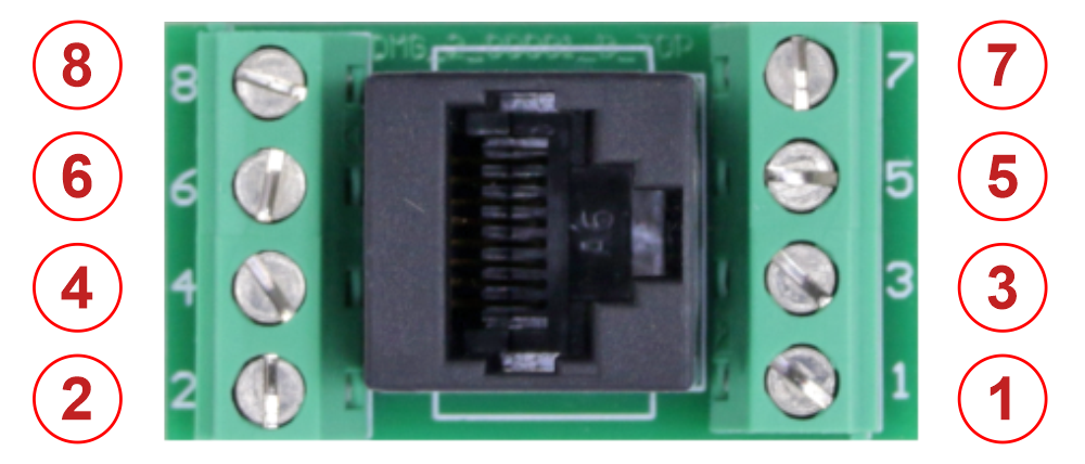
- PIN 1: Signal IN-2; common line for all floors of the single PIT8 board.
- PIN 2: Up button
- PIN 3: Programmable indication OUT-1 (default programming = Present)
- PIN 4: Power supply +24V (max 200 mA)
- PIN 5: Power supply GND
- PIN 6: Input IN-1 (isolated for each floor)
- PIN 7: Down button
- PIN 8: Programmable indication OUT-2 (default programming = Out of Service)