(v 1.3)

A simple APP for Smartphones available for free to all users wishing to call the lift without touching any buttons in the elevator car or at the floor.
Safety and usage cautions
Before installing our products, we recommend you to consult the section about safety and usage cautions at the link below.

Wiring Instructions
FreeRide connects locally with the BlueTooth Receiving Modules placed in the elevator car button panel and floor button panels.
No changes to the controller or to the wiring in the shaft are required. Simply add the Bluetooth Receiving Module to the elevator car button panel or floor button panels.
Connecting the Bluetooth Receiving Modules
IN THE CAR:
Use the following connection diagram to install and connect the EBTCOP main module and the EBT4EX expansion card(s) inside the elevator car operating panel:
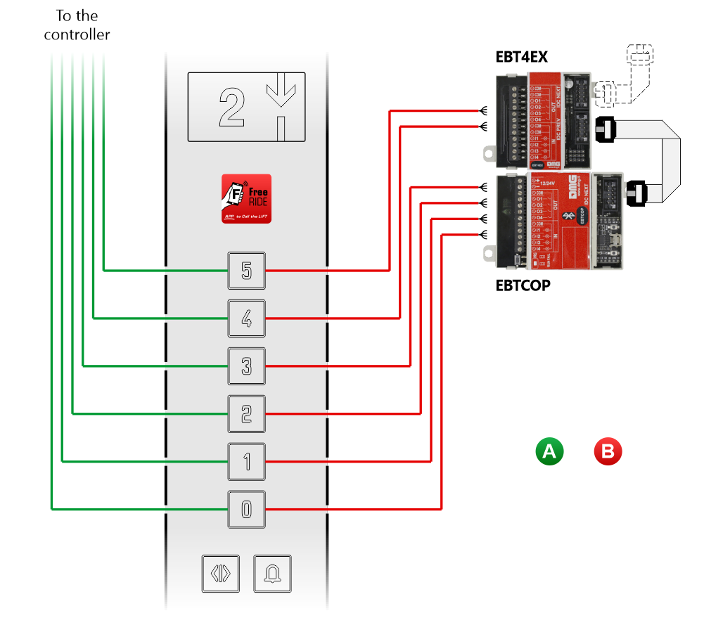
Each button must be connected to the EBTCOP (or EBT4EX) module following the same wiring diagram below. All cables must be wired in parallel with the existing wires.
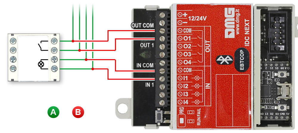
A) – EXISTING WIRING (for conventional mechanical activation)
B) – ADDITIONAL WIRING (for the use of FreeRide App)
AT FLOORS:
For each floor of the building, the (existing) landing operating panel (LOP) must be equipped with one EBTLOP Bluetooth card. Use the following diagram to connect the BT card to the call button(s):
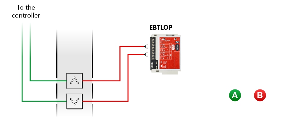
Each button must be connected to the EBTLOP module following the same wiring diagram below. All cables must be wired in parallel with the existing wires.
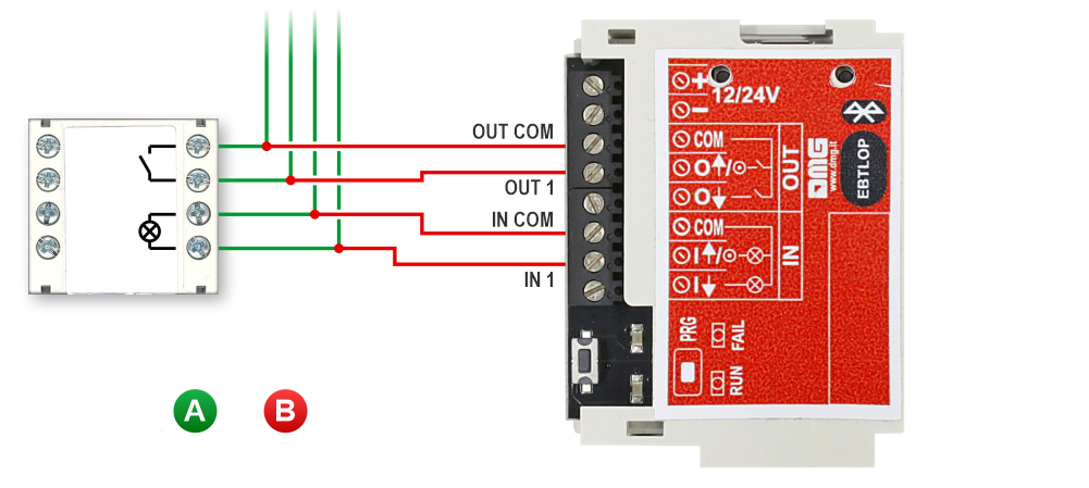
A) – EXISTING WIRING (for conventional mechanical activation)
B) – ADDITIONAL WIRING (for the use of FreeRide)
Settings
Setting the dip-switch to continue or close the expansion module chain
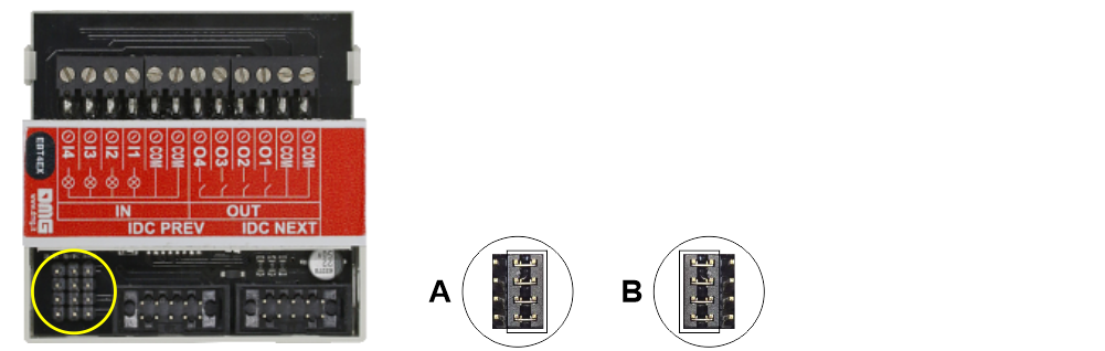
A) – Continue the expansion module chain
B) – Closes the expansion module chain
Setting Bluetooth Receiving Modules in the lift car

A) – Press the PRG button to put the Bluetooth module in Administrator mode.
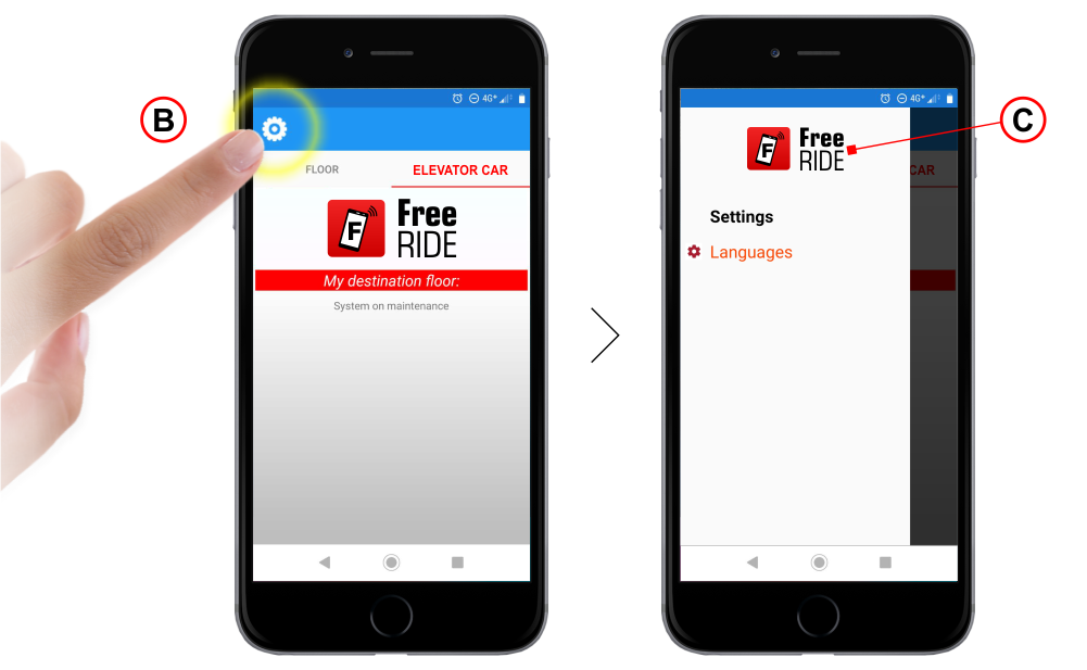
B) – Press the Config symbol to enter the menu.
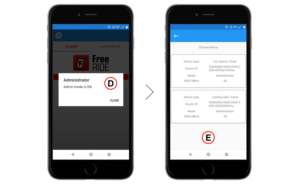
C) – Tap several times (about 5 times) on the FreeRIDE logo to log in in Administrator mode.
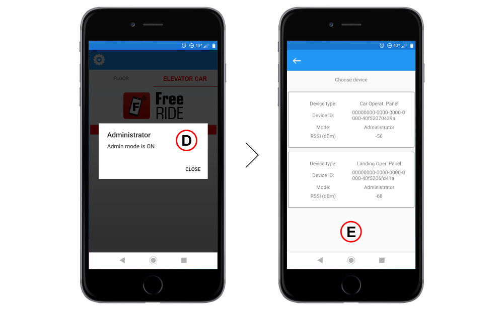
D) – Administrator mode is active.
E) – All the Bluetooth modules of the FreeRIDE system are displayed on the screen; select the one you want to configure. The lowest “RSSI (dBm)” value indicates the Bluetooth module with the strongest signal.
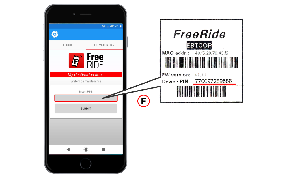
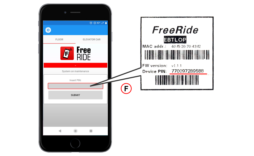
F) – Enter the PIN code included in the package (PIN code is the same for each installation equipped with the FreeRide system).
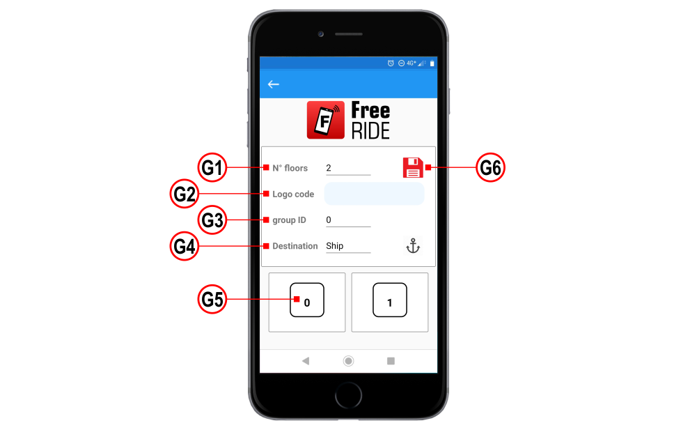
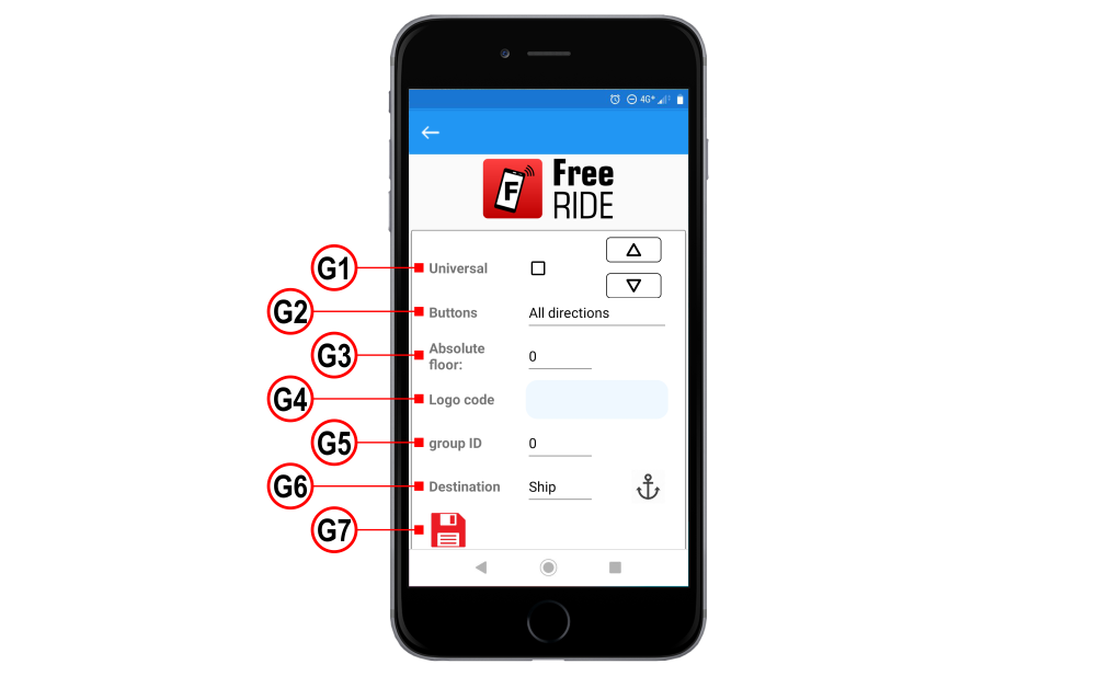
G1) – Set the total number of floors (total number of stops for lifts with double access).
G2) – Use this field “Logo code” to enter the customer code (10 digits) and show your logo on the FreeRide App.
Note: FreeRide may show a specific graphic logo on the App screen when in use (this area is normally set to blank). To do so, the installer must send the graphic logo to DMG and get the unique customer code in return.
G3) – The Group ID information shall be used for multiplex installations. See BT LOP module configuration below for more information.
G4) – Use this parameter to select the intended use of the system. The following operating modes apply:
Building mode: this is the standard operation mode for the FreeRide system. Users may connect to both floor and lift car BT modules, without priority.
Ship mode: in this special mode, dedicated to lifts in cruise ships, the user must first connect to the floor module and place his/her call before he/she can access the lift car module.
Ship boarding mode: this mode is used in cruise ships during passenger boarding when car modules must be accessible anytime as lifts are normally already present at the main floor.
G5) – This section may be used to indicate the proper floor symbol for each virtual button. You can also set the lowest floor value and automatically set up the other floors.
G6) – Save the configuration.
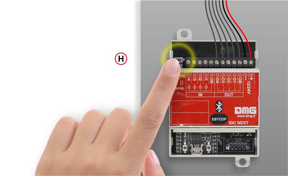
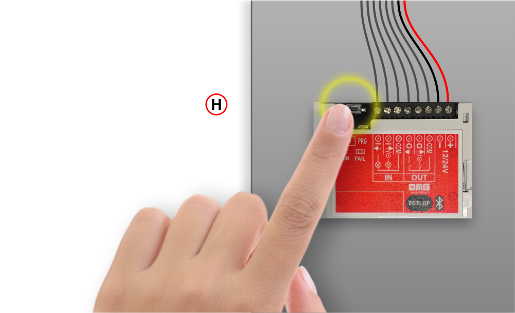
H) – Press the PRG button to exit the Administrator mode.
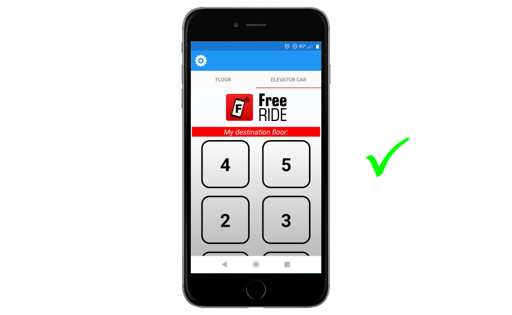
Restart the FreeRIDE application. The layout of the button panel is displayed on the smartphone screen.
Settings Bluetooth Receiving Modules at floors

A) – Press the PRG button to put the Bluetooth module in Administrator mode.
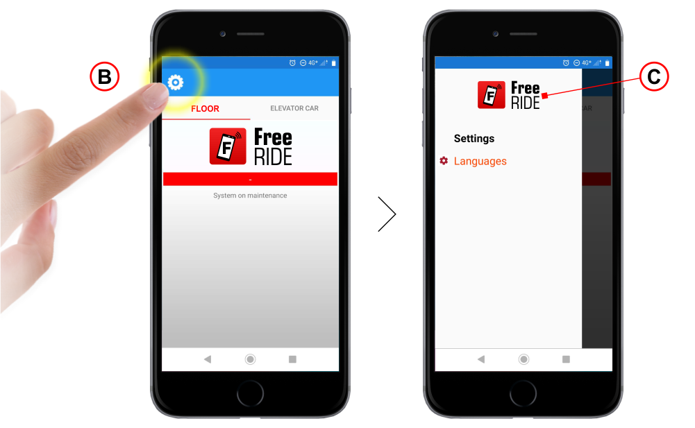
B) – Press the symbol indicated to enter the menu.
C) – Tap several times (about 5 times) on the FreeRIDE logo to log in in Administrator mode.
D) – Administrator mode is active.
E) – All the Bluetooth modules of the FreeRIDE system are displayed on the screen; select the one you want to configure. The lowest “RSSI (dBm)” value indicates the Bluetooth module with the strongest signal.
F) – Enter the PIN code included in the package (PIN code is the same for each installation equipped with the FreeRide system).
G1) – SAPB (no registration) option: if active, allows to choose the single button only.
G2) – Choose the button configuration (One button, two-button; direction of the arrow symbol)
G3) – Set the total number of floors (total number of stops for lifts with double access)
G2) – Use this field “Logo code” to enter the customer code (10 digits) and show your logo on the FreeRide App.
G5) – The Group ID information shall be used for multiplex installations. BT LOP modules assigned to the same group of lifts in a building with multiple lifts must have the same Group ID. Up to 5 different Group IDs can be used.
G6) – Use this parameter to select the intended use of the system. The following operating modes apply:
Building mode: this is the standard operation mode for the FreeRide system. Users may connect to both floor and lift car BT modules, without priority.
Ship mode: in this special mode, dedicated to lifts in cruise ships, the user must first connect to the floor module and place his/her call before he/she can access the lift car module.
Ship boarding mode: this mode is used in cruise ships during passenger boarding when car modules must be accessible anytime as lifts are normally already present at the main floor.
G7) – Save the configuration.
H) – Press the PRG button to exit the Administrator mode.
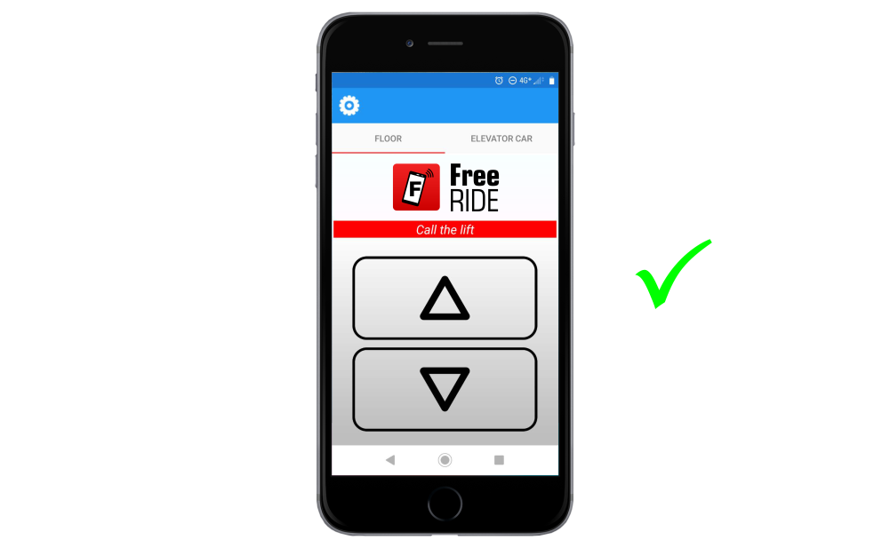
Restart the FreeRIDE application. The layout of the button panel is displayed on the smartphone screen.
Datasheet
| EBTCOP card | |
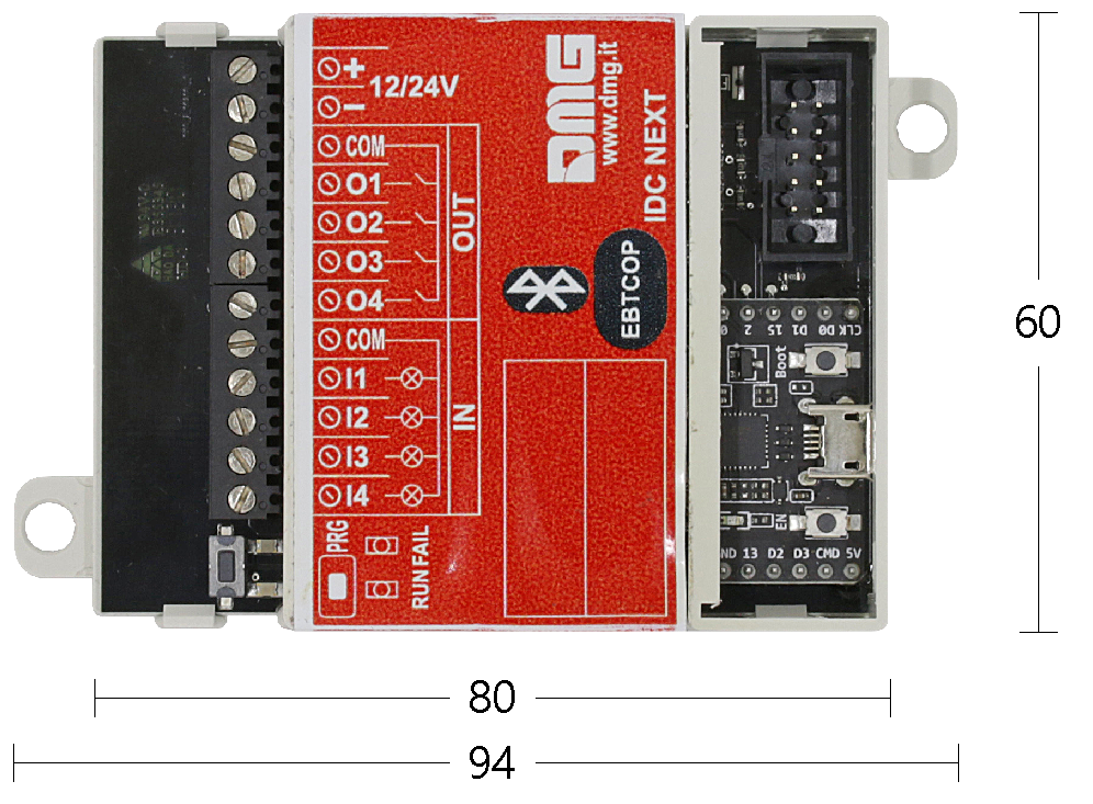 | Power Supply: 12/24V dc – 30 mA 4 opto-isolated inputs 12/24V – 5 mA 4 opto-isolated outputs 12/24V – 60 mA (MAX) 4 call buttons managed, expandable up to 36 overall stops |
| EBT4EX expansion card | |
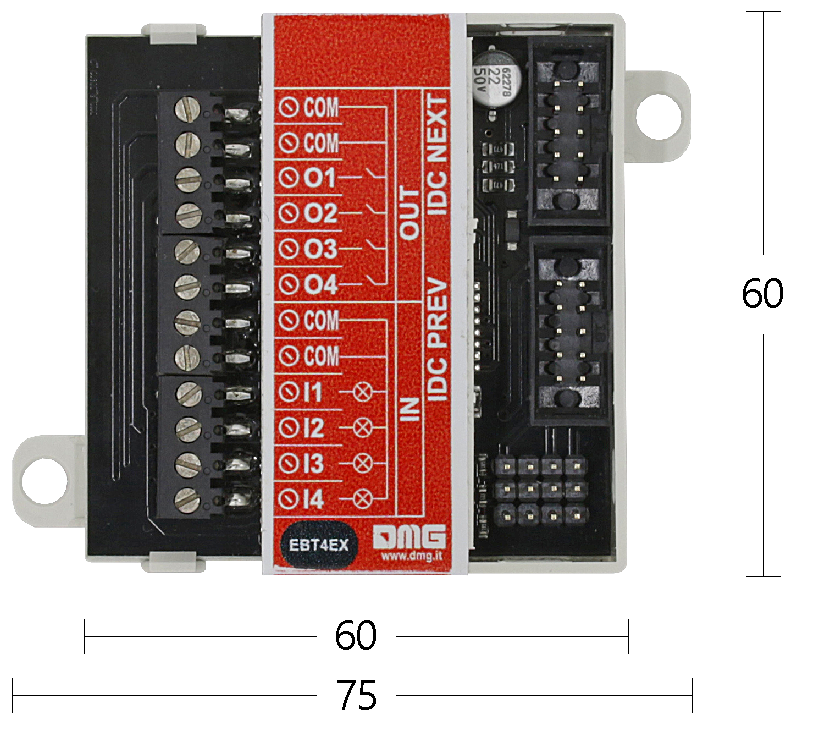 | Power Supply: 12/24V dc – 10 mA 4 opto-isolated inputs 12/24V – 5 mA 4 opto-isolated outputs 12/24V – 60 mA (MAX) 4 call buttons managed |
| EBTLOP card | |
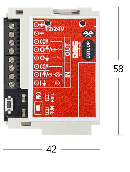 | Power Supply: 12/24V dc – 30 mA 2 opto-isolated inputs 12/24V – 5 mA 2 opto-isolated outputs 12/24V – 60 mA (MAX) 2 call buttons managed (up/down) |
Link
You can download the FreeRIDE application at the following links or by framing the relative QRcode:
Apple Store

Google Play

Download
| Reference | Version | Link |
|---|---|---|
| 1.3 (current version) | Download PDF (English) | |