(v 2.1)
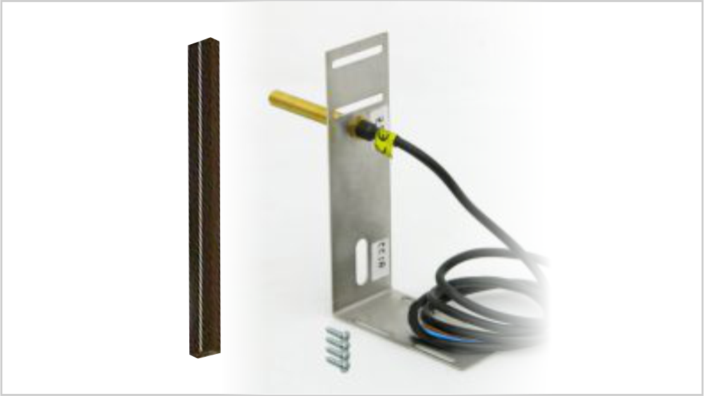
The Autonomous Positioning System for the DMG displays of the Raffaello, Giotto and Matisse series, allows to show the lift position and direction independently from controller. The interface uses the sensors signals installed on the top of elevator car.
If available, it is possible to use the same position sensors used by controller.
If NOT availale, you have to install:
a) – 1 magnetic sensor (Normally Open) on the cabin + 1 magnet at every floors for counting position.
b) – 1 magnetic sensor (Normally Open / Closed) on the cabin + 1 magnet at main floor for the RESET.
In this interface there is a CAN BUS serial line for piloting the position indicators of floor.
For all other functions (Voice Synthesizer, gong, indicators, etc.) please refer to the display user manual.
Safety and usage cautions
Before installing our products, we recommend you to consult the section about safety and usage cautions at the link below.

Wiring Instructions
The autonomous counting system with displays requires two sensors, one for counting and one for reset. Below is a table with the number and type of magnets to be used.
| Elevator speed: | < 2 m/s | one 15 cm magnet per stop + 1 magnet for reset. |
| Elevator speed: | ≥ 2 m/s | one 30 cm magnet per stop + 1 magnet for reset. |
Connection with single door zone signal
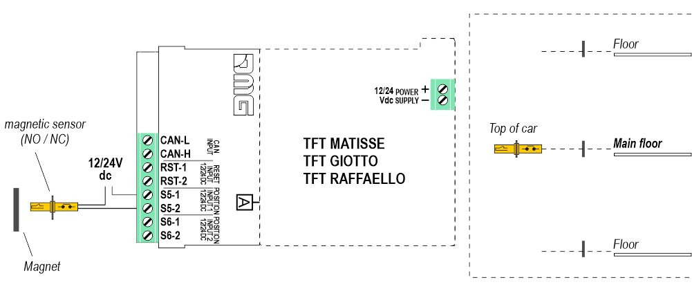
The elevator car position changes every time the sensor passes in front of the magnets.
Where available, the door zone sensor already present in the installation can be used.
Connection with double door zone signal
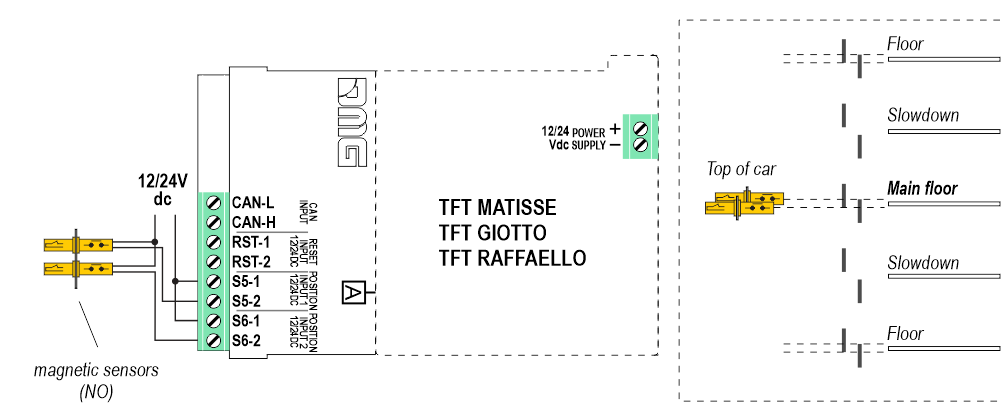
The elevator car position changes when the sensors pass in front of the magnets when they are simultaneously activated.
Valid only in the case of magnetic sensors already installed on the system.
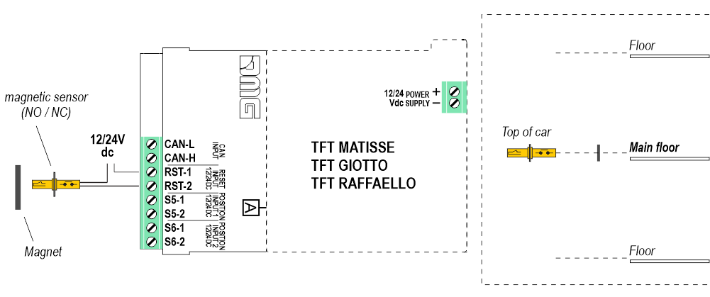
RESET circuit connection
The interface needs a RESET for the initial restoring and for eventual restoring due to a system shutdown.
RESET with magnetic sensor (NO or NC)
Where available, the reset sensor already present in the installation can be used.
The resets occurs every time the elevator car reaches the main / lowest floor.
The reset occurs every time the main / lowest floor call is served when the button lamp goes off.
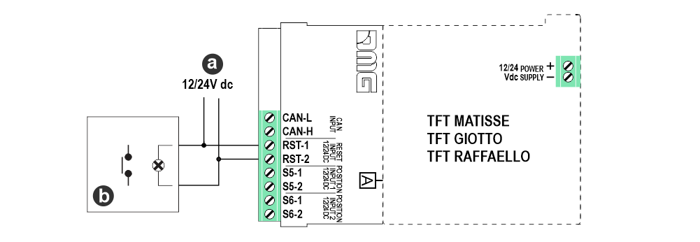
a) – Lamp output from controller
b) – Main floor button light
Interface connection with position indicators of floor
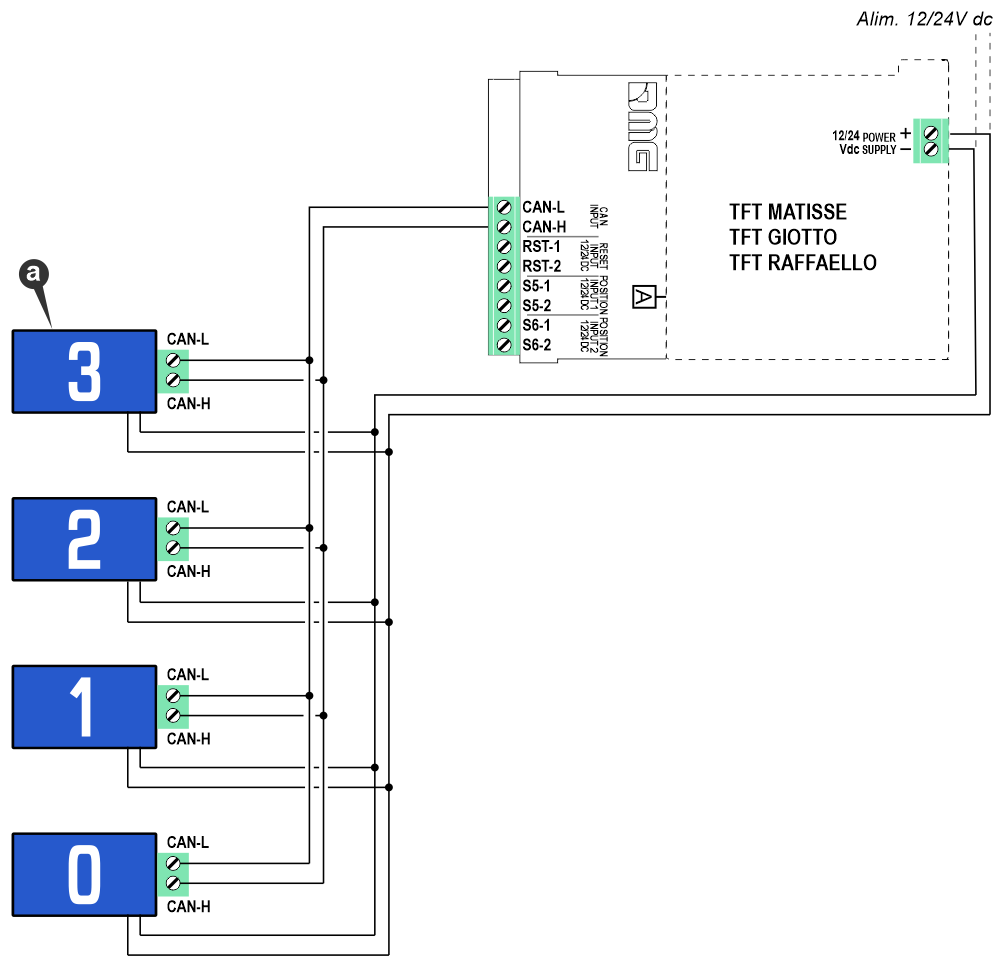
a) – Position Indicators of floor (CAN interface only)
Settings
Reset setting

1) – Normally Open Contact (See “Wirings > Reset with magnetic sensor“)
2) – Normally Closed Contact (See “Wirings > Reset with magnetic sensor“)
3) – Main Floor Button (See “Wirings > Reset with main floor button light“)
Door zone type setting

1) – Single Input (See “Wirings > Connection with single door zone signal“)
2) – Double Input (See “Wirings > Connection with double door zone signal“)
Arrow velocity threshold setting

Datasheet
| Power Supply | 12/24V dc |
| Number of manageable stops | -9 / 99 |
| Max system speed | Up to 2 m/s with 15cm magnet for counting floors From 2 m/s to 4 m/s with 30cm magnet for counting floors |
| Power supply position/reset input | 12/24V dc Opto-insulated |
| Serial line for landing pos. indicators | CAN BUS 10 kbps DMG protocol |
| Operating temperature | -10°C ÷ +50°C |
Accessories
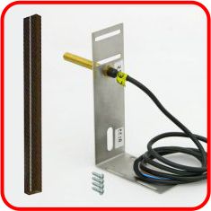
1 Magnetic sensor kit
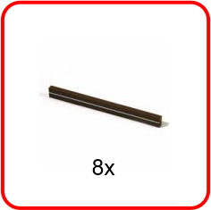
8 Magnets for counting kit (15cm)
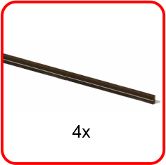
4 Magnets for counting kit (30cm)
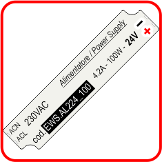
24V Power supply
Download
| Reference | Version | Link |
|---|---|---|
| 1.9 | Download PDF (English) | |
| Reset with magnetic sensor (revision) | 2.0 | Download PDF (English) |
| Max system speed (revision) | 2.1 (current version) | Download PDF (English) |
