(v 1.2)


Matisse + MosaicONE
Matisse is the core platform that underpins the most advanced DMG visual devices. It powers the following multimedia products and applications:
Matisse Multimedia Display (7″ and 10,1″)
Matisse XXL Multimedia Display (15,6″ and 21″)
Matisse DSD – see details on the relevant page
Matisse Touch – see details the relevant page
Matisse Mirage
Matisse Media Hub – see details the relevant page
General system layout
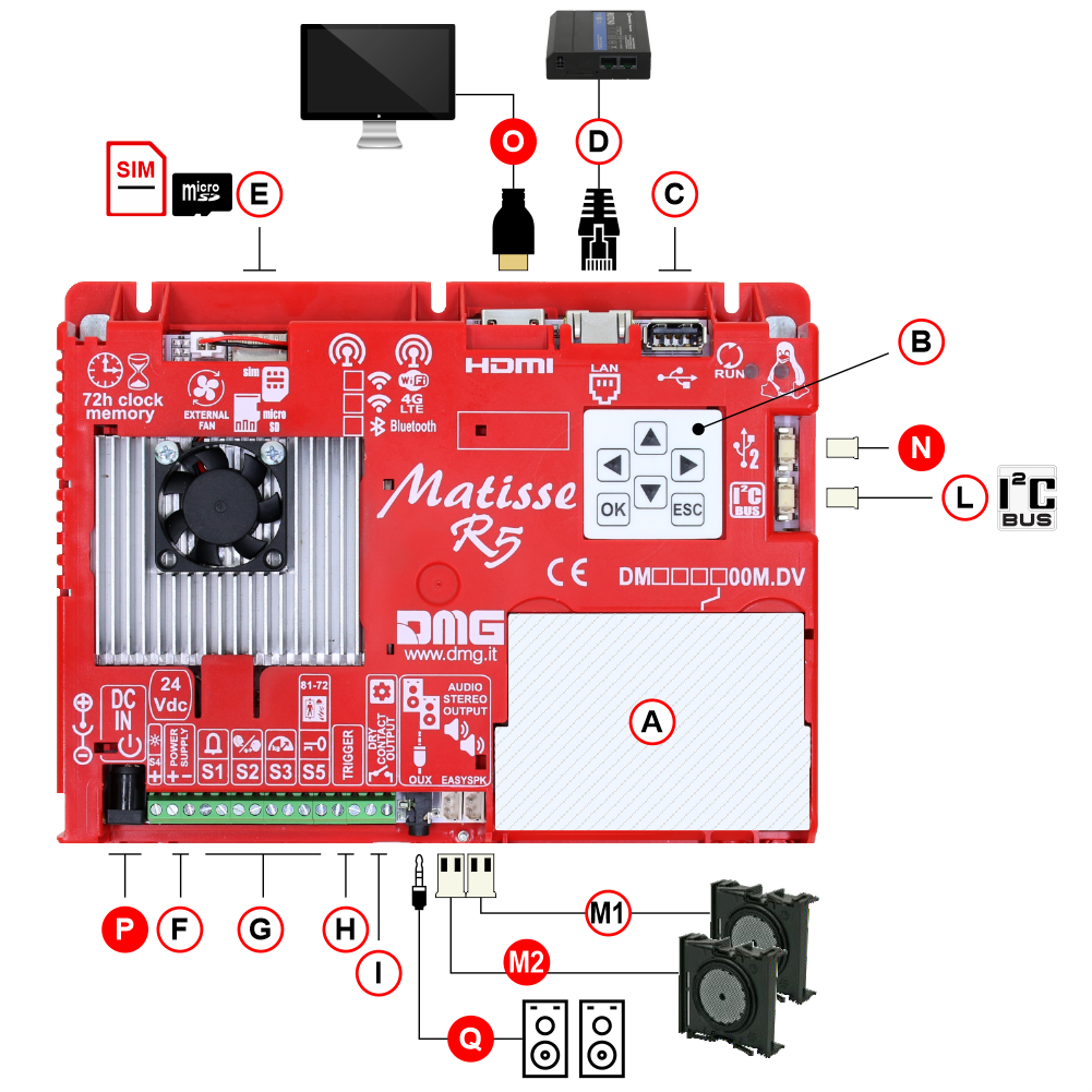
| ( A ) | Slot for DMG interface cards | |
| ( B ) | Programming keys | |
| ( C ) | USB plug | |
| ( D ) | ETHERNET/LAN plug | |
| ( E ) | SIM card / MicroSD card slot | |
| ( F ) | Power Supply | |
| ( G ) | Signal inputs | |
| ( H ) | Sound trigger input | |
| ( I ) | Dry contact output | |
| ( L ) | I2C bus | |
| ( M1 ) | 1st Audio OUT (External speakers) | |
| * | ( M2 ) | 2nd Audio OUT (External speakers) |
| * | ( N ) | USB port |
| * | ( O ) | HDMI output |
| * | ( P ) | Optional prewired power supply (5,5mm standard jack) – 40W AC/DC 100-240Vac 24Vdc 1.66A |
| * | ( Q ) | Stereo audio output for speakers – 3,5mm standard jack |
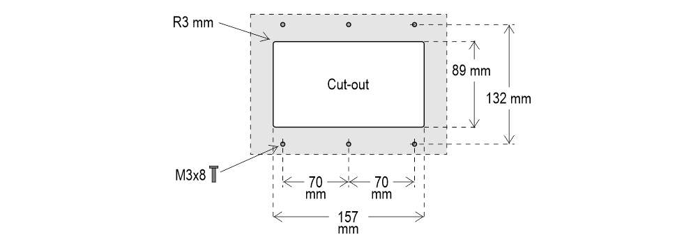
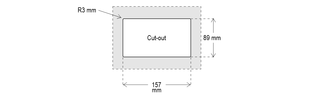
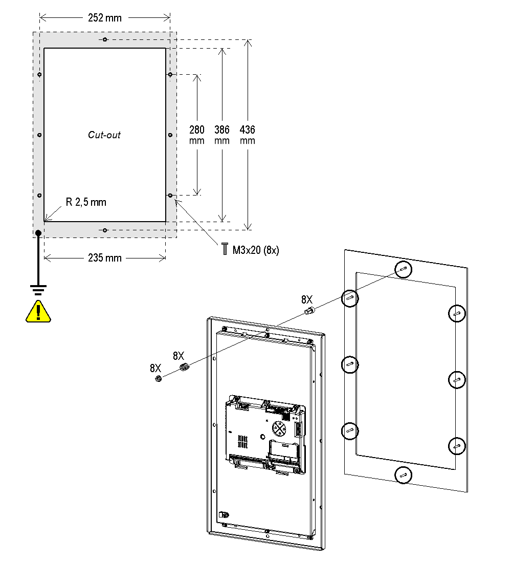
Mounting
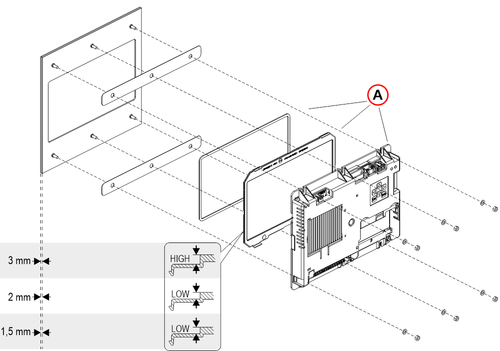
A) – These 3 components may have already been assembled in DMG.
With pins on backplate (for 1/2 mm pushbutton panel)
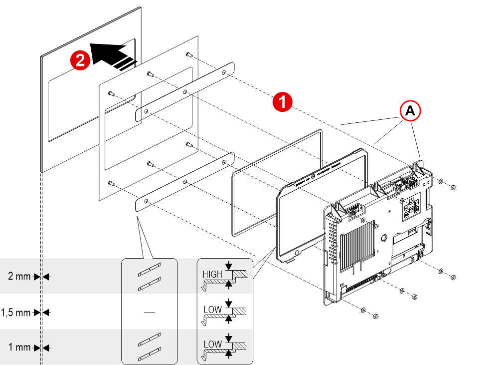
1) – Assemble all the components.
2) – First of all remember to remove the double-sided tape from the subplate.
A) – These 3 components may have already been assembled in DMG.
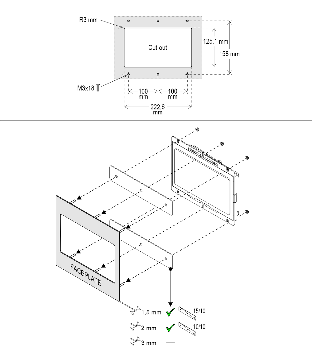
With pins on backplate (for 1,5/2 mm pushbutton panel)
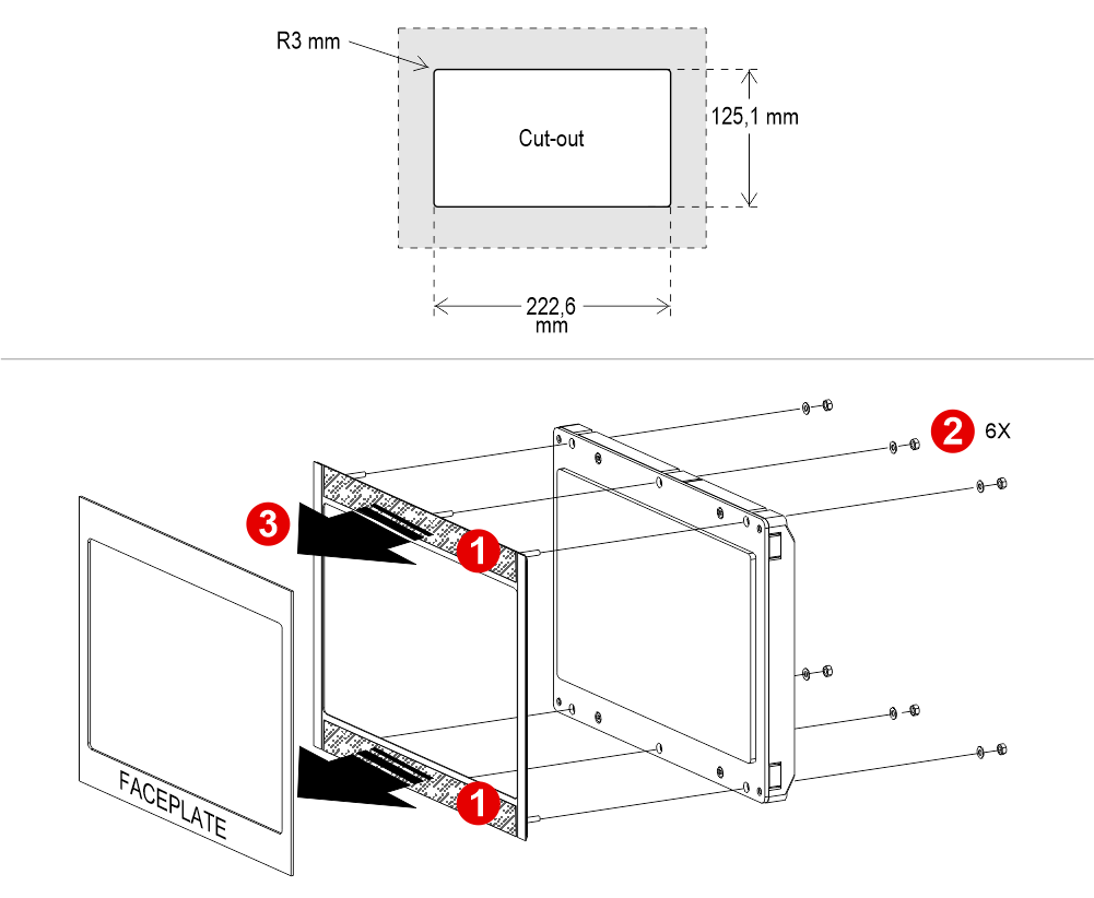
1) Remove the double-sided tape
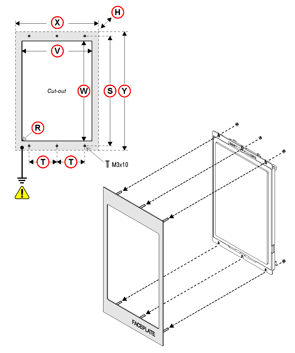
| TFT | DIMENSIONS: (X x Y x H) | CUT-OUT (V x W - R) | STUDS SxT |
|---|---|---|---|
| TFT 15,6" | 232,5 x 430,5 x 44 | 192.6x343,6 mm - R0,1 | 413x100 |
| TFT 21,5" | 324,5 x 564,5 x 49 | 266.6x475,6 mm - R0,1 | 547x140 |
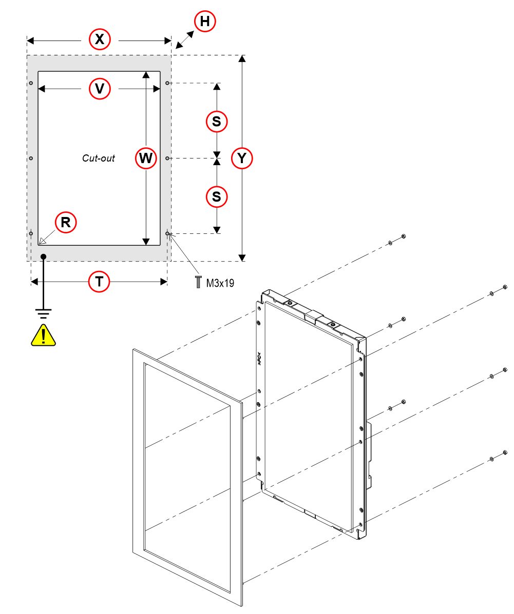
| TFT | DIMENSIONS: (X x Y x H) | CUT-OUT (V x W - R) | STUDS SxT |
|---|---|---|---|
| TFT 15,6" | 244 x 374 x 49,5 | 195x346 mm - R0,25 | 152,4x228,6 |
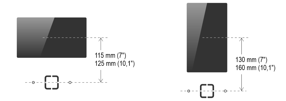
The pins are M3×16.
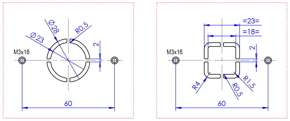
Below are the center-to-center distances between the speaker grid and the display (horizontal and vertical).
Wiring
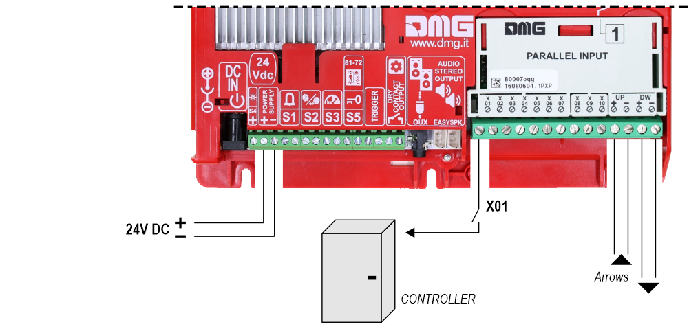
Basic Wiring
1 Wire / Floor
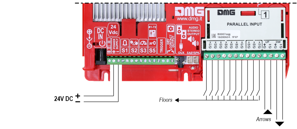
 10 floors max.
1 Wire / Segment
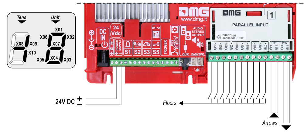 29 floors max. (-9, 0, 19)
Gray / Binary
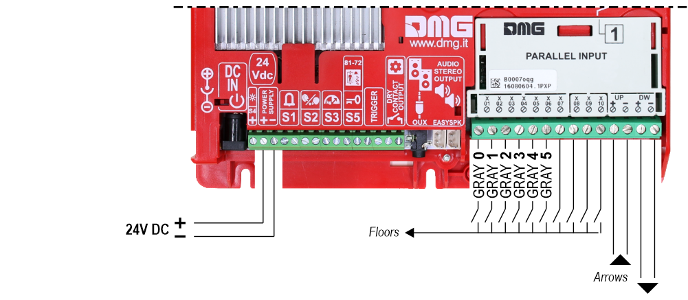 72 floors max. (-9, 0, 62)
TKE/MEA/Autinor
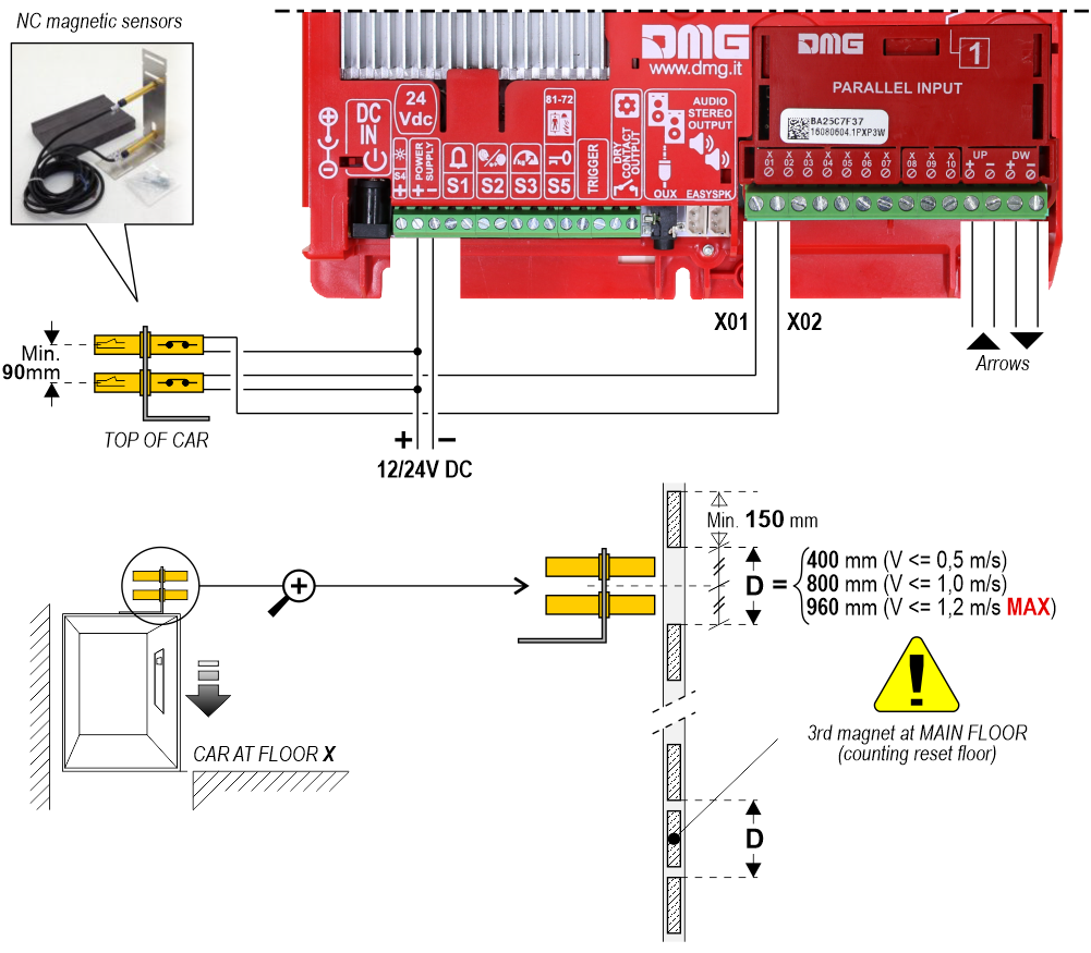
Indipendent sensor
With this connection, the following settings are required in the programming menu:
Matisse M1 / Input
• Pos. Sensor (Manual) – The arrows are controlled by inputs
• Pos. Sensor (Auto) – The arrows are controlled by sensors
Matisse M1 / Options / Interface options / Display configuration
• COP (Car operating panel display)
Matisse M1 / Options / Interface options / Common selections
• Negative
 For more details please refer to the
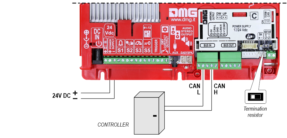
 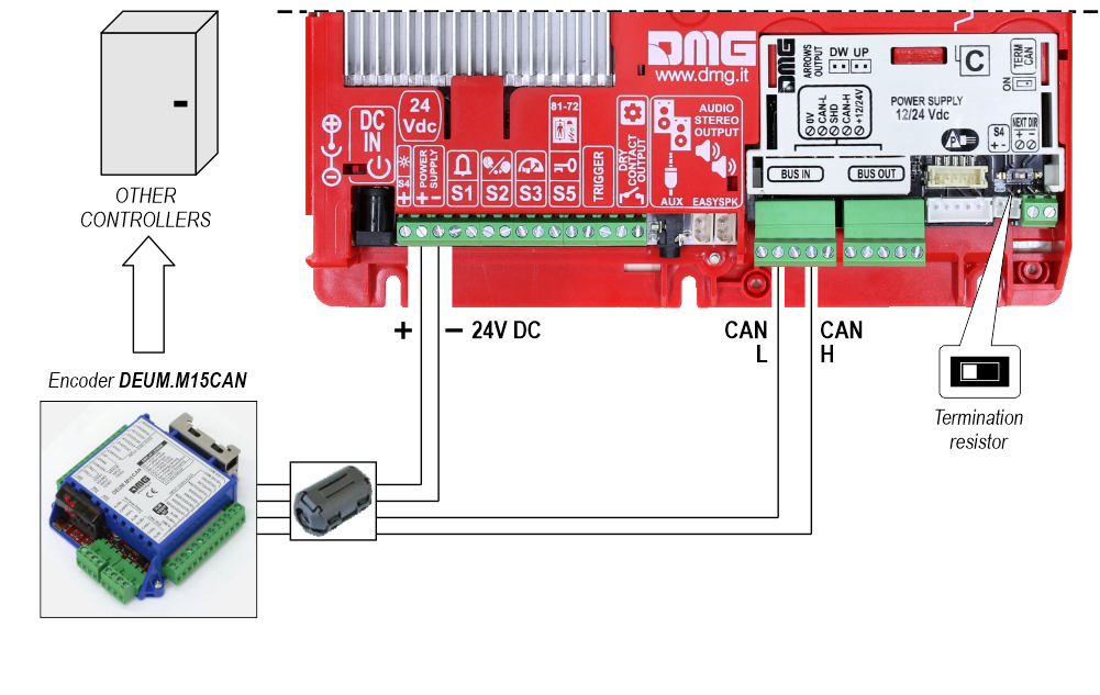 RS485 serial
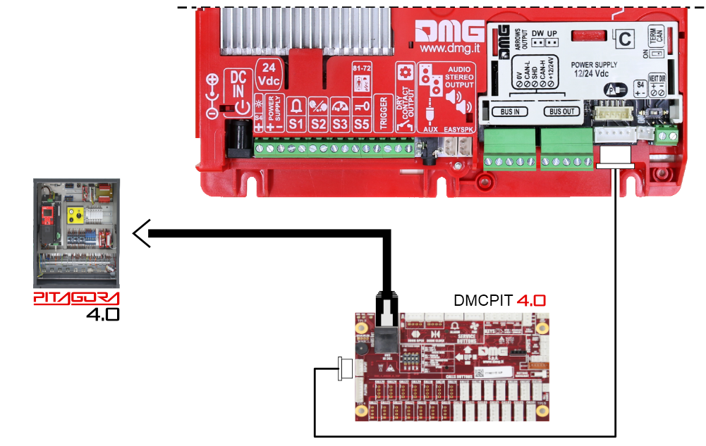
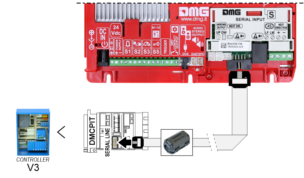
If available, it is possible to use the same position sensors used by the controller.
If NOT availale, you have to install:
• 1 NO magnetic sensor on the cabin + 1 magnet at every floors for counting position.
• 1 NO magnetic sensor on the cabin + 1 magnet at main floor for the RESET.
In this interface there is a CAN BUS serial line for piloting the position indicators of floor.
For all other functions (Voice Synthesizer, gong, indicators, etc.) please refer to the display technical support page.
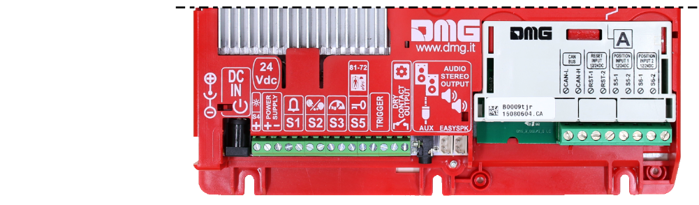
Autonomous positioning System
Power supply wiring details
Check that the display panel has been ground connected.
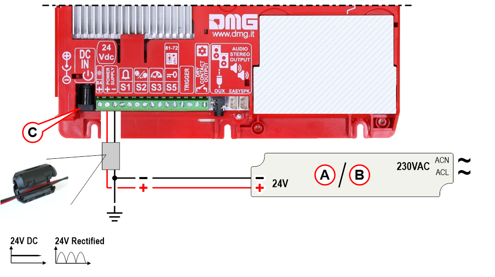
A) – EWS.AL224 – Optional power supply (0.75A – 18W – 24V) for:
- Matisse CPU – Absorption 150mA
- Matisse 7″ – Absorption 270mA
- Matisse 10,1″ – Absorption 330mA
B) – EWS.AL224_100 – Optional power supply for Matisse XXL (4.2A – 100W – 24V):
- Matisse 15,6″ – Absorption 600mA
- Matisse 21,5″ – Absorption 800mA
C) – Optional prewired power supply for Matisse XXL (5,5mm standard jack) – 40W AC/DC 100-240Vac 24Vdc 1.66A
Service messages wiring
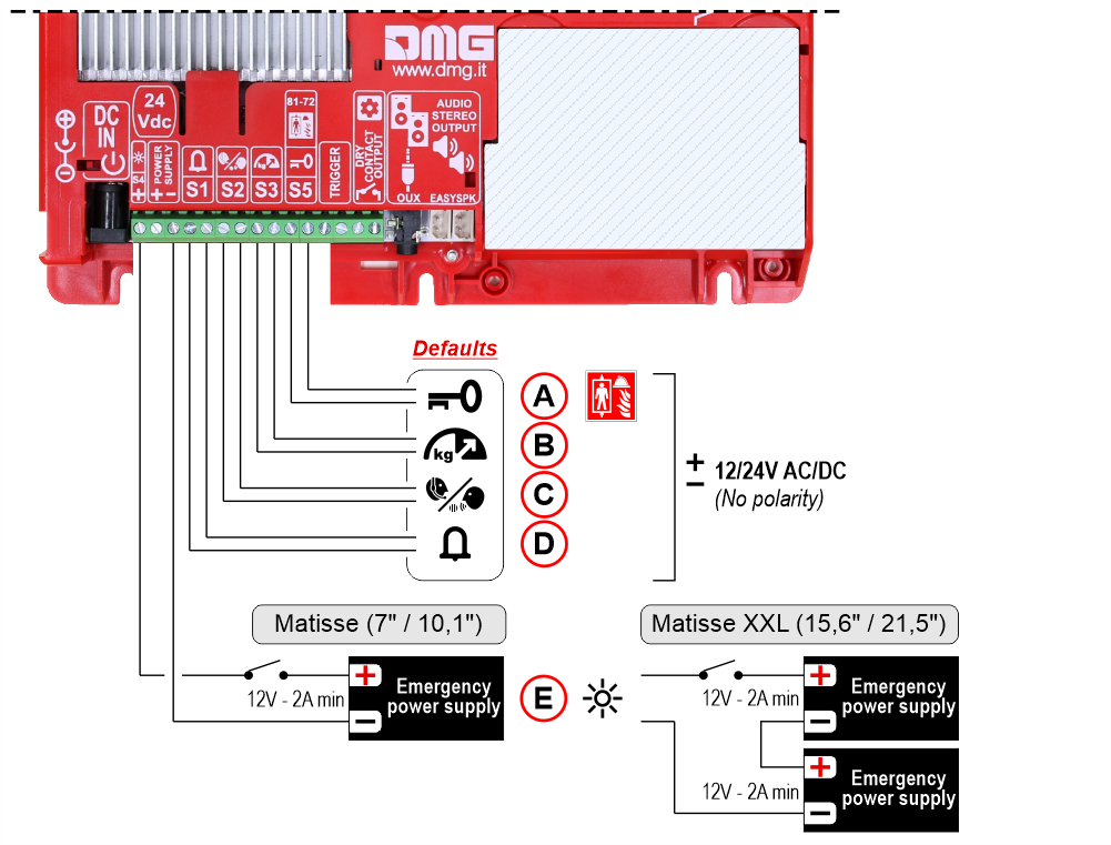
A) – S5 – Reservation / Firefighters operation
B) – S3 – Overload
C) – S2 – Communication established
D) – S1 – Alarm sent
E) – S4 – Antipanic light (Make sure the batteries are charged)
TRIGGER command wiring (parallel inputs only)
This input must be used to trigger floor-related voice messages and gong.
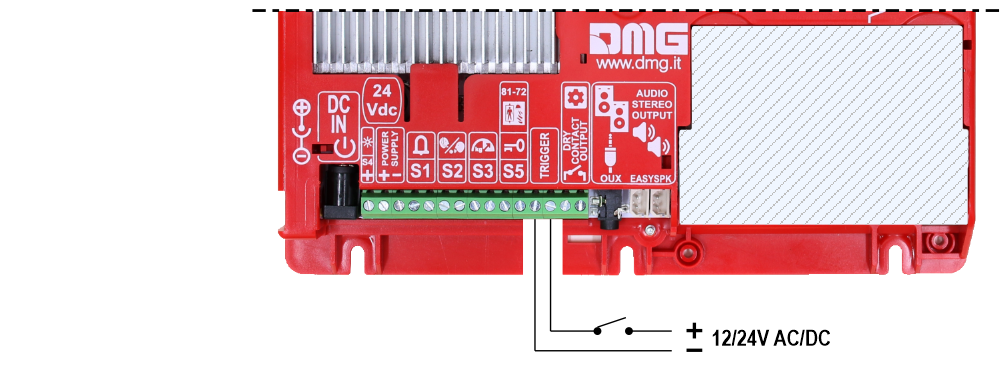
No polarity
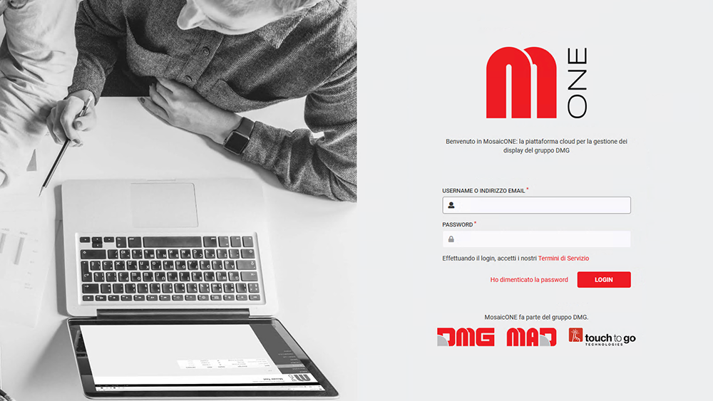
Connecting the Matisse to MosaicONE
Matisse displays are designed to be natively connected to the Internet. Any visual content on the screen can be created and modified using Mosaic One, the cloud-based software for digital content management.
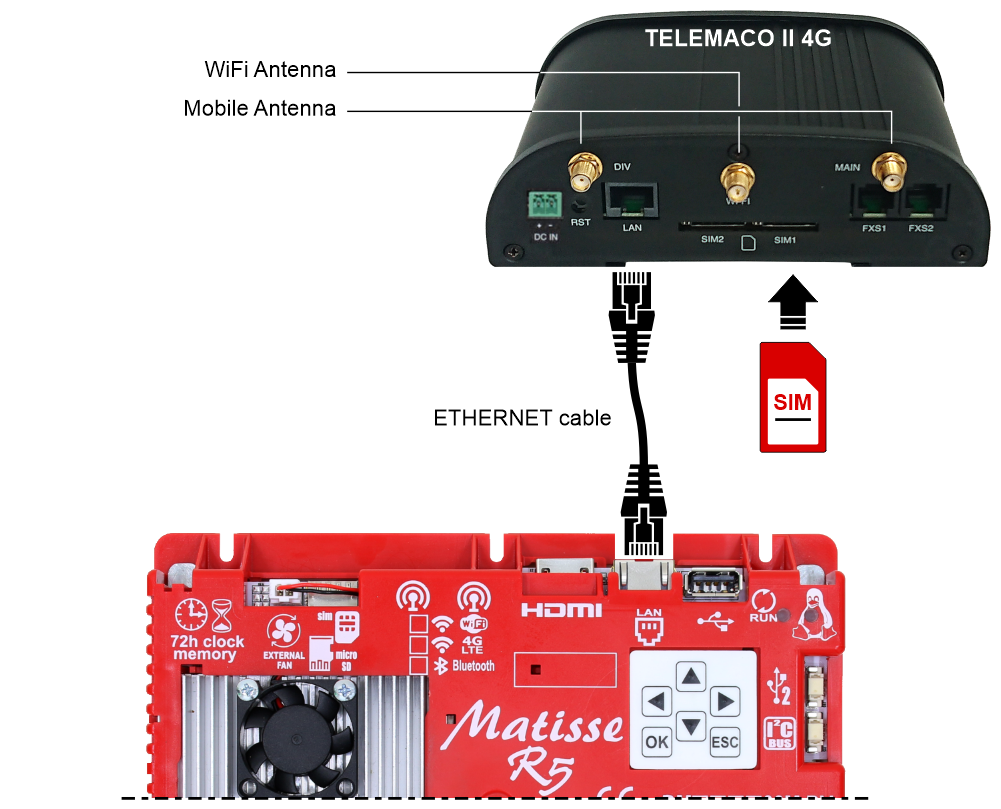
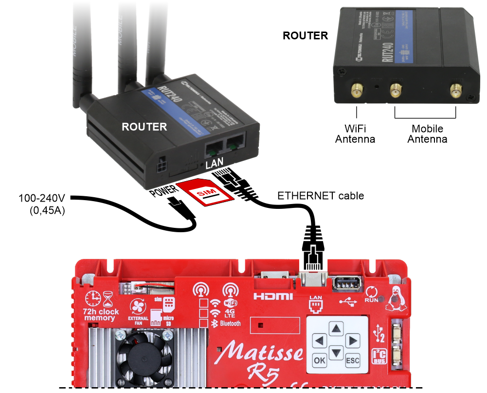
Connecting the Matisse to the Internet
More information at this link.
Direct connection with Matisse
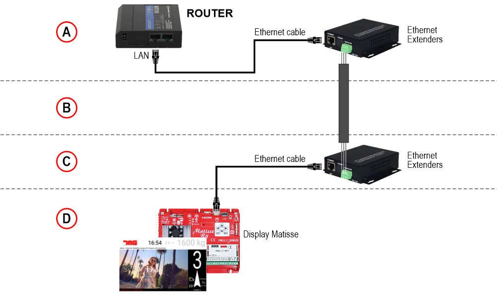
Connection via ethernet extenders
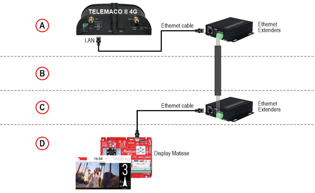
A) – Machine Room
B) – Shaft
C) – Top of cabin
D) – Matisse display in the elevator car.
Direct connection with Matisse
Connection via ethernet extenders
A) – Machine Room
B) – Shaft
C) – Top of cabin
D) – Matisse display in the elevator car.
Connecting multiple Matisse displays
It is possible to connect multiple Matisse displays via a HUB.
Below is a schematic diagram of the wiring.
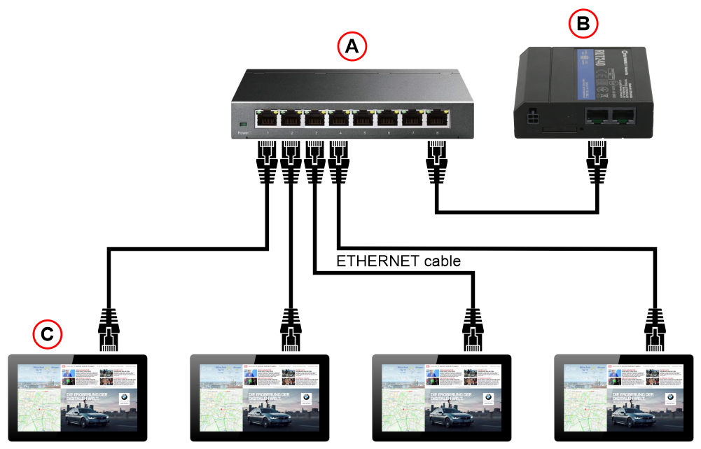
A) – Hub device to connect the modem to multiple Matisse displays
B) – Modem
C) – Matisse displays
(Follow the instructions provided with the device)
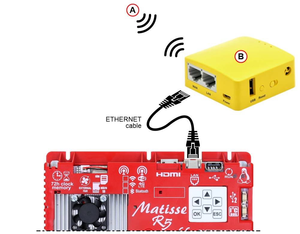
A) – Existing Wi-Fi network
B) – Wi-Fi bridge device
Using MosaicONE for screen content management
See https://dido.dmg.it/knowledge-base/mosaicone-online-software/ for full MosaicONE user instructions.
Connecting external accessories
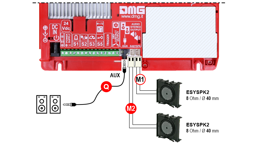
M1 ) – 1st Audio OUT (External speakers)
* M2 ) – 2nd Audio OUT (External speakers)
* Q ) – Stereo audio output for speakers – 3,5mm standard jack
* Matisse XXL / DSD / Touch only
This device is suitable for playing stereo audio.
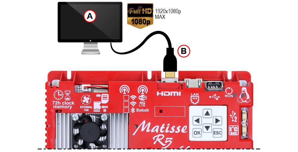
A) – HDMI Monitor/TV
B) – HDMI Cable or HDMI/DVI adapter (NOT supplied)
See the LIVE+ dedicated page for all details.
Setting on-board parameters
All the Matisse visual setups can be viewed and modified using Mosaic One. Some parameters are only available in the on-board menu:
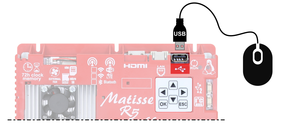
Navigating the on-board Menu
Use the 6-key pad on the back of the device to access and navigate the on-board Menu of the Matisse.
Press OK to enter the menu.
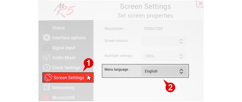
Setting the menu navigation language
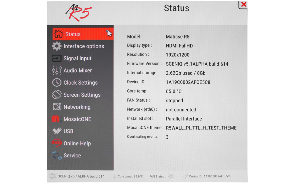
Information about the installed Matisse display
Setting the encoding protocol and offset
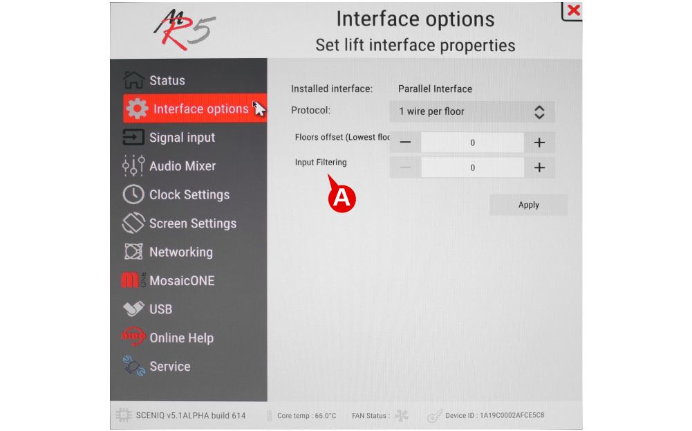
A) – Setting the display delay at the change of floor. The display delay helps avoiding visualization errors during the floor change.
0 (disabled)
1 (100 ms)
———
20 (2000 ms)
Setting the energy saving function and a dry contact on the terminals S1/…/S5
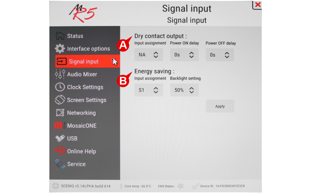
A) – It is possible to activate a dry contact by associating it directly with one of the signals present on board (S1-S5) which, once powered, will control the contact. It is also possible to set the activation or deactivation delay as needed.
B) – It is possible to activate the energy saving function by associating it directly with one of the signals present on board (S1-S5).
Volume setting of all functions (Master) and multimedia
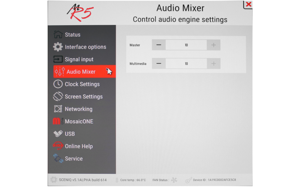
Audio Master: Set the volume of all functions
Date & time settings
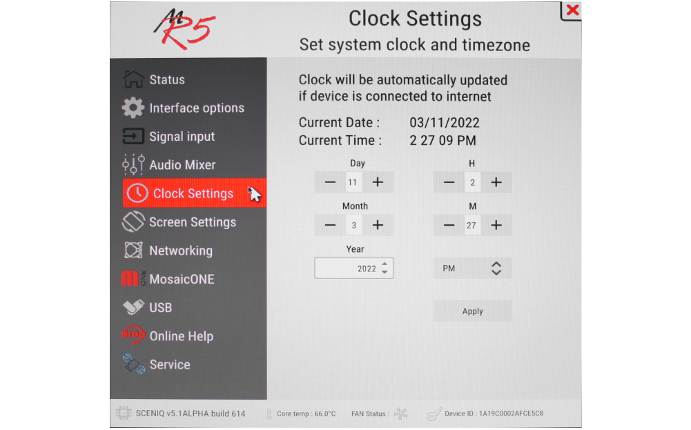
Matisse has a built in clock. In the event of a power failure, the board will maintain the parameters relating to the date and time for 72h, after which it will be essential to re-enter the parameters manually (if not connected to the network).
Setting the language, backlight and screen rotation
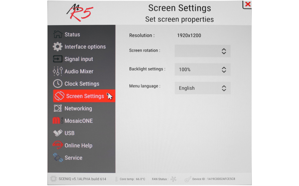
Screen rotation is used more for external monitors; you can rotate the image 180 °.
The backlight values of the screen will remain fixed and should not be confused with the power saving function.
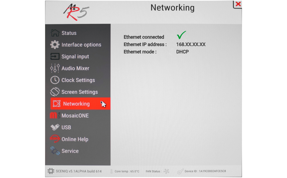
Information on the network connections status
Information on the connection status to the MosaicONE cloud sw and related diagnostics.
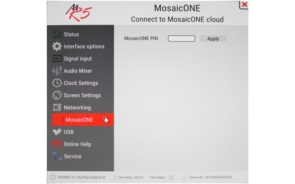
For information on how to associate Matisse to the MosaicONE sw, see the section “Pairing with MosaicONE software” of the DIDO web page on MosaicONE.
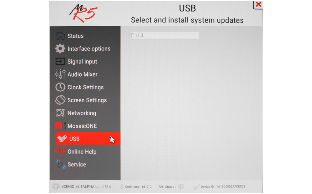
Matisse display update
To update devices not connected to the internet, proceed as follows:
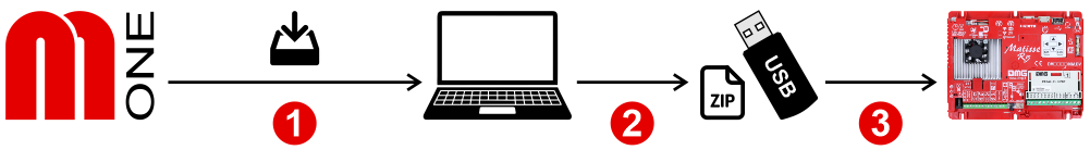
1) – Export the chosen configuration (.MPACK) from the MosaicONE cloud software.
2) – Copy the file to USB memory in .ZIP format.
3) – Insert the memory directly into the USB port of the Matisse display and use the contextual menu.
Online help
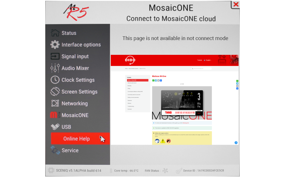
The online help is linked directly to the DMG DIDO web page for the Matisse display. Here you will find all the information for installing, connecting and programming the device.
Datasheet
| 7" | 10,1" | 15,6" | 21,5" | |
| Overall dimensions (WxH) | 178 x 144 mm Horizontal | 243 x 169 mm Horizontal | 232,5 x 430,5 mm Vertical | 324,5 x 564,5 mm Vertical |
| Depth (from front plate | 22,6 mm | 38,5 mm | 43,5 mm | 43,5 mm |
| Screen dimensions | 156,5 x 88,5 mm | 222 x 124,6 mm | 192,0 x 243,0 mm | 266,0 x 475,0 mm |
| Viewing area | 154,9 x 85,9 mm | 222,7 x 125,3 mm | 193,6 x 344,2 mm | 248,3 x 476,6 mm |
| Resolutions | 1024 x 600 px 65.000 colours | 1920 x 1080 px 65.000 colours |
||
| IPS screen | Yes | |||
| Power supply | 24V DC ±10% | |||
| Absorption (24V) | 270 mA | |||
| Absorption in Emergency mode with S4 at 24Vdc | 240 mA | |||
| Operating temperature °C | -10°C / 50°C | |||
| Storage temperature °C | -20°C / 60°C | |||
| Mass storage | 8 GB EMMC | |||
| RAM | 2 GB LPDDR4 | |||
Software
MosaicONE Guide
Troubleshooting
| Fault description | All Matisse visual & media systems | |
|---|---|---|
| Installation errors | The display does not light up | Check for the presence of 24VdC voltage. |
| Make sure that the type of voltage complies with that required (direct voltage, not alternating, not rectified). | ||
| Check the correct polarity on the power terminals. | ||
| Even if the display seems off, check that the red FAIL led on the back is not on, if it is, in this case the problem would be of a different nature. Please contact DMG. | ||
| Check that the characteristics of the system can meet the consumption requirements in terms of current of the devices, as recommended and for correct operation, it may be necessary to use additional power supplies (available from DMG). | ||
| Display Flashes or restarts continuously | Make sure that the type and voltage value comply with those required, if the problem persists it can be attributed to a HW defect. | |
| Steady red LED | Device in FAIL. Indicates a Serious system ERROR, inherent in a hardware defect or other unresolvable defect. Please contact DMG. | |
| Flashing red LED | Device in FAIL. Indicates a generic system ERROR, in this case there may have been a problem relating to the graphic or fw programming of the device, an update via USB may be sufficient. Ex: the display shows "NO GRAPHIC FOUND" associated with the flashing red LED (see error messages). | |
| The display does not show numbers and/or arrows | Make sure that the type and voltage value comply with those required for the inputs, make sure you have correctly set the type of common. | |
| Error messages | High display temperature Device is on standby. Wait for temperature to decrease. The system will start automatically | This is an "alert" message. The device has detected a rise in temperature. The system automatically shuts down all the functions (except those for the lifts) to allow you to return to the permitted values. The prolongation of this defect causes the block of the device (see next point) |
| Display malfunction detected Please contact technical assistance | This is a serious error message. It causes the system to block and can occur in 2 ways: 1 - the alert message of the previous point occurs 10 times (the causes are those reported in this point) 2 - the temperature rise is extremely fast. This causes the system to interpret the defect as an assembly problem and in any case label it as "potentially harmful". in this case it is not possible to intervene remotely. |
|
| Wrong recognition Coding interface | For displays that use coding interfaces (slots), the data of the inserted interface is shown on the screen at startup. If an inconsistency occurs, the defect is to be attributed to the HW. | |
| The display turns on but does not start up or freezes during start up | This defect manifests itself with the missing screen of the penguins of the "Linux" operating system or with the interruption of the DMG writing (which behaves like a loading bar); if either of these conditions occurs, please contact DMG. | |
| The display turns black after functioning but restarts correctly after forced restart. Only for Matisse 15,6", 18,5", 21,5" | This defect was detected ONLY on LVDS screens and therefore all Matisse BIGs (DSD -Touch and NOT). Please contact DMG. | |
| The display shows the indication "E" followed by a number X | In this case, it is a generic error indication due to an incorrect setting of the display. Please contact DMG | |
| No connection | The display does not connect to the Internet. | MAIN CAUSES: 1 - if using a SIM with 4G router (Telemaco II or Teltonika), check signal quality. 2 - if a SIM with a 4G router is used (Telemaco II or Teltonika), check traffic availability. 3 - if a SIM with a 4G router is used (Telemaco II or Teltonika), check that a DATA plan is active. 4 - Make sure that the ETHERNET connection is direct or with dedicated devices (HUB, Extender etc). 5 - avoid splices and extensions directly on the ETHERNET cable. 6 - check for the presence of Firewall. USEFUL CHECKS TO PERFORM: 1 - Check that the green LED on the back (ETHERNET port) flashes when the network cable is connected. 2 - Only with Matisse R5, make sure that the LEDs on the ETHERNET connector are on (steady yellow and flashing green). 3 - if DHCP connection check in the menus that the device takes an automatic IP. 4 - Only with Matisse R5, connect to the DIDO web page directly from the device menu. |
| Display defects | The display shows vertical lines | If the lines are fixed and black, please contact DMG. |
| The display shows horizontal lines | ||
| The display is white | Please contact DMG. | |
| The display has inverted colors or with a "negative" effect | Please contact DMG. | |
Download
| Reference | Version | Link |
|---|---|---|
| V4 version | V4 | Download PDF (English) |
| MosaicONE version | 1.0 | Download PDF (English) |
| Added U.S. version | 1.1 | Download PDF (English) |
| Improved readability of the content of this page | 1.2 | Download PDF (English) |