
(v 1.0)

Safety and usage cautions
Before installing our products, we recommend you to consult the section about safety and usage cautions at the link below.

Introduction
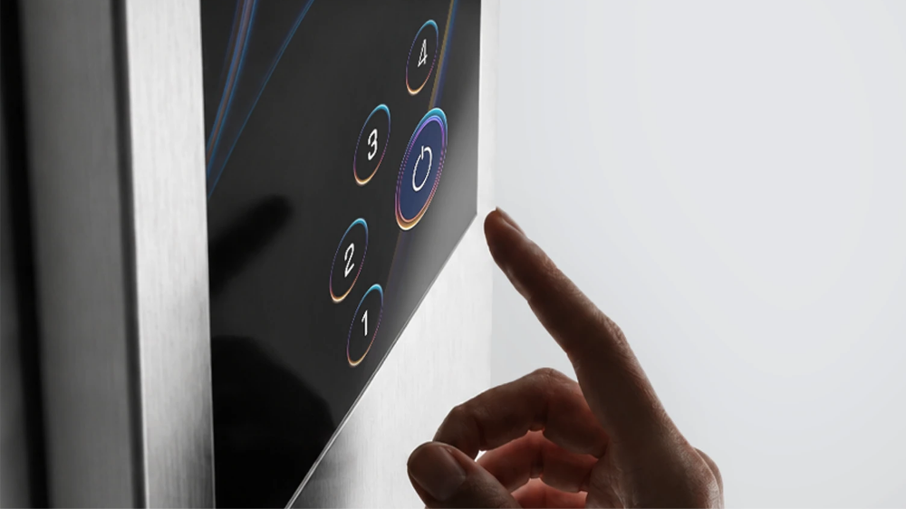
DMG Matisse Touch is the new touchscreen display platform for elevators, designed as an alternative to traditional mechanical push-button panels. By replacing conventional buttons with a touch interface, it provides maximum flexibility in user interface design while combining functionality, customization, and durability in a single solution.
Available in 15.6“, 21.5“, and 29“ stretched formats, it features an IK8-rated anti-glare touch glass, ensuring reliability and excellent readability even in high-traffic installations.
Mounting
 Mounting
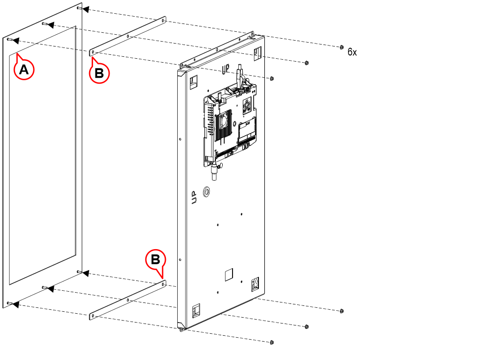 A) Faceplate
B) Spacer(s)
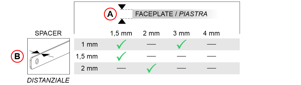
The combined thickness of the plate and spacer(s) must always be 4 mm.
Refer to the table below for the correct spacer selection.
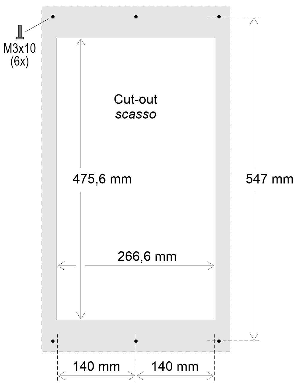
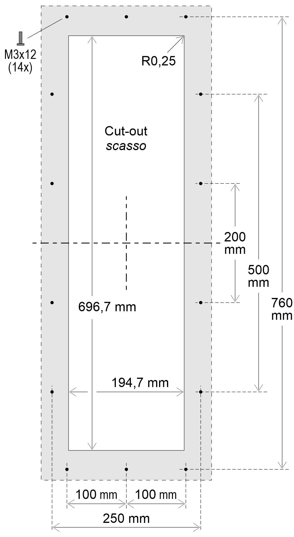
Mounting
A) FaceplateB) Spacer(s)
The combined thickness of the plate and spacer(s) must always be 4 mm.
Refer to the table below for the correct spacer selection.
Mounting
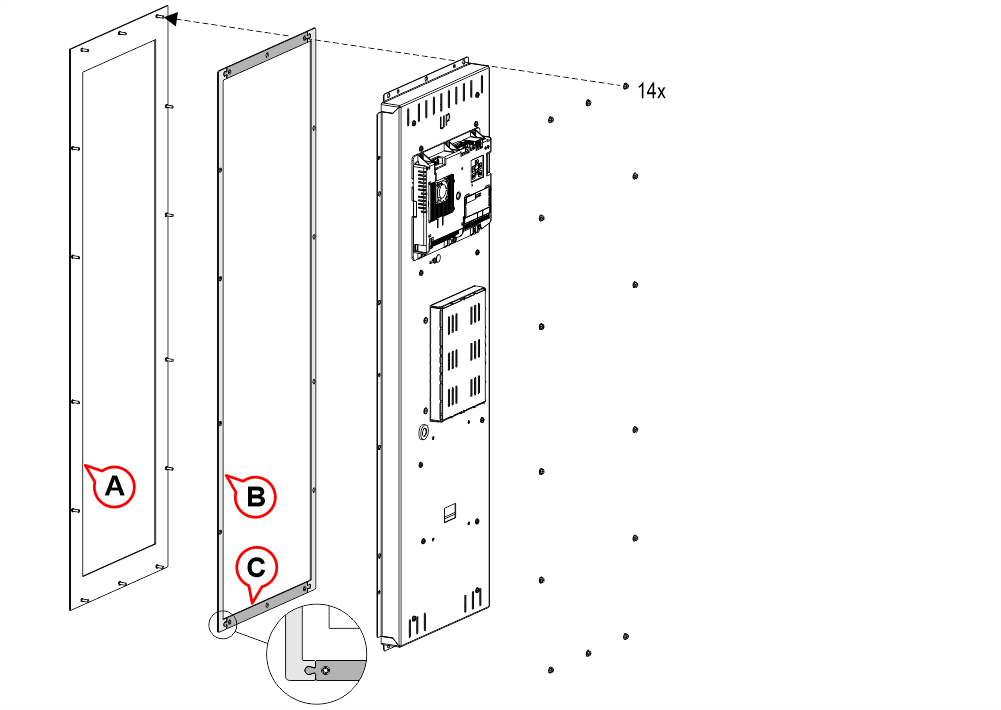 A) Faceplate
B) Long spacer
C) Short spacer
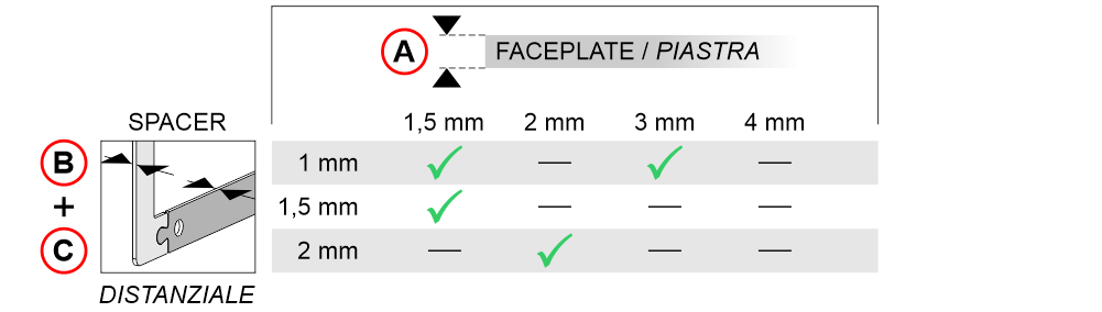
The combined thickness of the plate and spacer(s) must always be 4 mm.
Refer to the table below for the correct spacer selection.
Wiring Instructions
Connection of the Matisse M1 display to the TTG touch module
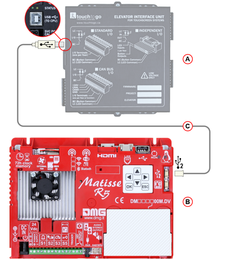
A) TTG touch module
B) Matisse M1 display
C) USB Cable (USB-B – Picoblade 4)
Connection with the Pitagora 4.0 system
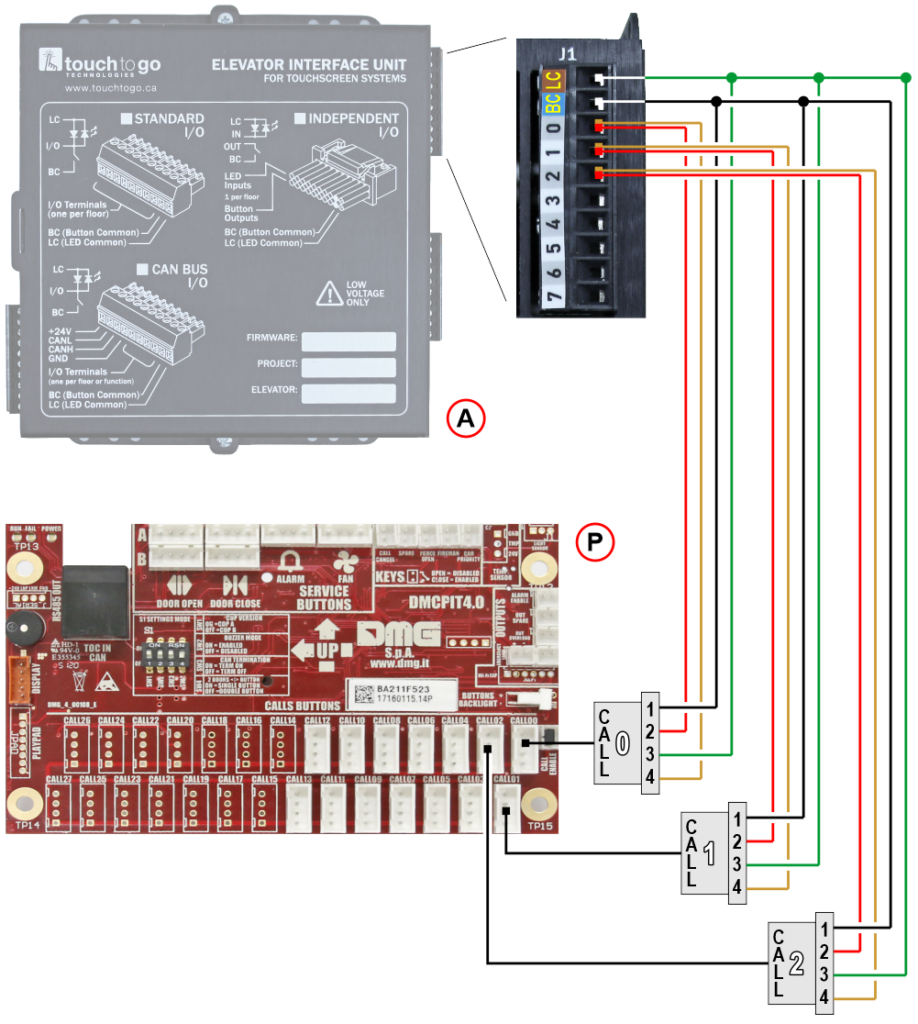
A) TTG touch module
P) DMCPIT interface board
LC) C+, LED common
BC) C-, button common
Connection with the Junior 4.0 controller
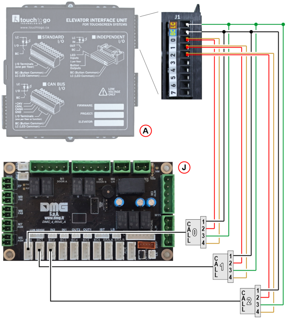
A) TTG touch module
J) Car dispatching board
LC) C+, LED common
BC) C-, button common
Connection with third-party controller
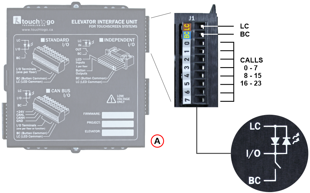
A) TTG touch module
LC) C+, LED common
BC) C-, button common
I/O) Calls – One input/output terminal for each floor
Diagnostic LED
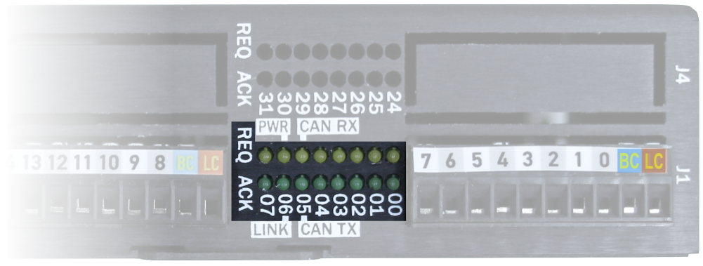
REQ – Call request LED
The Call Request LEDs illuminate when the touchscreen system is requesting a floor. Under normal operating conditions, when a floor is requested, the LEDs turn on momentarily and the corresponding relay contacts also close briefly. The call request duration is fixed at approximately 0.5 seconds. Keeping a touchscreen button pressed does not extend the request beyond this time interval.
ACK – Call confirmation LED
The Call Confirmation LEDs illuminate when the elevator indicates that a call has been registered. They remain on until the elevator arrives at the requested floor. This behavior is equivalent to that of a conventional illuminated push button, which lights up after the call has been registered.
Troubleshooting
| Problem | Checks | Expected result |
|---|---|---|
| The elevator does not respond to touchscreen floor calls | 1) Disconnect the 10-pin black terminal block from the elevator interface board. 2) Verify that the elevator wiring operates correctly on its own: • Measure the voltage between LC (C+) and BC (C-). It should be approximately 24 VDC. • Measure the voltage between any floor terminal and BC (C-). It should be approximately 24 VDC, provided that no call is currently registered for that floor. 3) Simulate a floor call by connecting BC (C-) to the desired floor terminal for approximately 0.5 seconds. | The elevator should register the call and travel to the selected floor. |
| Call confirmation indicators do not operate correctly | 1) Verify that approximately 24 VDC is present between the floor terminal and BC (C-) when no call is active. 2) Simulate a floor call by connecting BC (C-) to the floor terminal for approximately 0.5 seconds. 3) Measure the voltage again between BC (C-) and the selected floor terminal. | • During an active call, the voltage should drop to approximately 0 VDC. • Once the elevator reaches the requested floor and the call is cleared, the voltage should return to approximately 24 VDC. |
Datasheet
| Dimensions | TFT 15,6″ : 225×425 mm (H 51,3 / H60 mm) TFT 21,5″ : 315×560 mm (H 51,3 / H60 mm) TFT 29″ : 260×775 mm (H 59 / H68 mm) |
| Viewing area | TFT 15,6″ : 193,6×344,2 / 1080×1920 pixel / 16M colors TFT 21,5″ : 268,1×476,6 / 1080×1920 pixel / 16M colors TFT 29″ : 196,4×698,4 / 540×1920 pixel / 16M colors |
| Power supply (position input) | 24V DC ±10% |
| Absorption | TFT 15,6″ : 650 mA TFT 21,5″ : 600 mA TFT 29″ : 1900 mA |
| Operating temperature | TFT 15,6″: 0°C ÷ +50°C TFT 21,5″: -10°C ÷ +50°C TFT 29″: 0°C ÷ +50°C |
Download
| Reference | Version | Link |
|---|---|---|
| 1.0 (current version) | Download PDF (English) |