
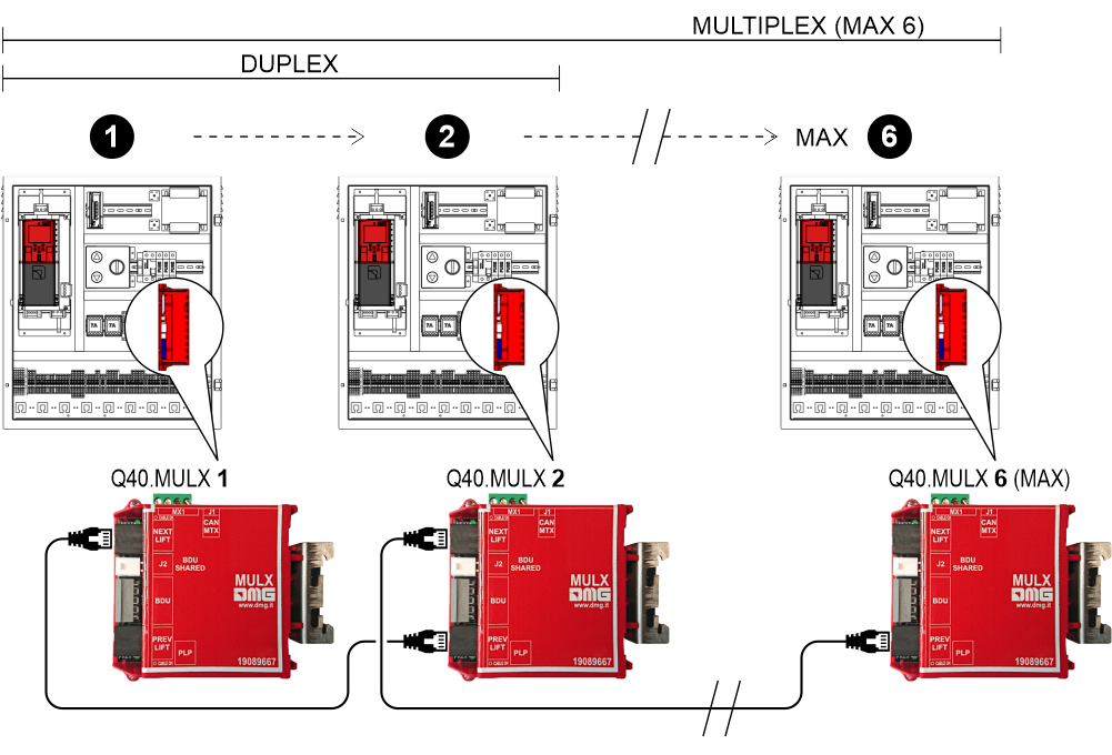
The Pitagora 4.0 control panel can manage multiplex systems up to 6 lifts.
The solution requires the use of a Q40.MULX electronic board mounted on the DIN rail of each control panel of the multiplex system. Each Q40.MULX multiplex board is equipped with two connectors (PREV / NEXT) and an ethernet cable for connection to the multiplex boards of the previous and next control panel.
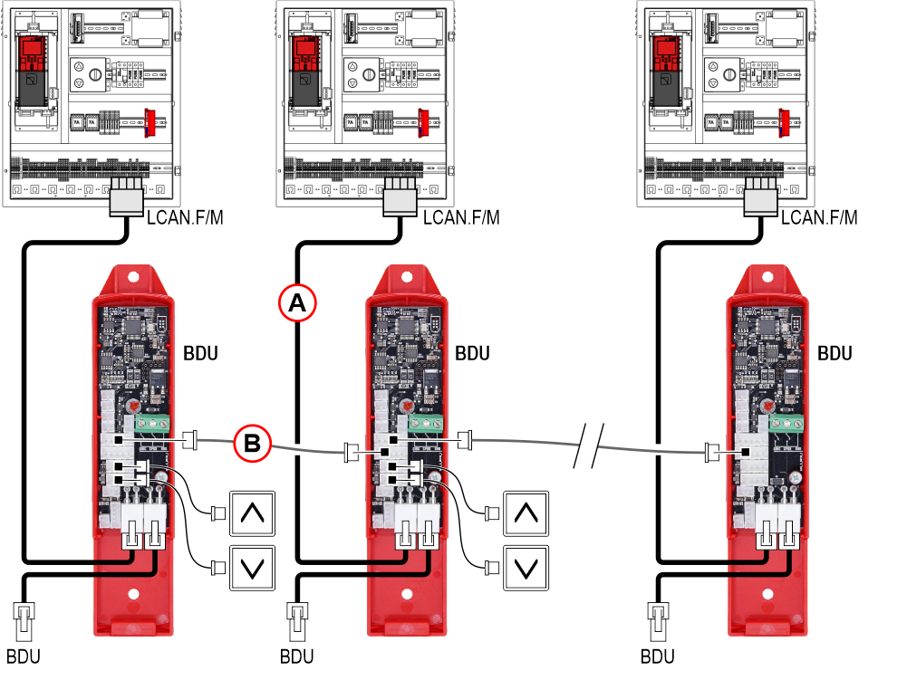
Each controller Pitagora 4.0 must be connected by a specific cable (A) to the closest BDU.
It is also recommended to connect the BDUs on the same floor by means of a 5-pole JST cable (B); in this way, in the event of a blackout of one of the Controllers, the button and the beep device will continue to operate calling one of the other lifts still in operation.
Below are some specific examples of duplex configurations.
| Floors in Multiplex | Controller A floors | Controller B floors |
|---|---|---|
| 7 | 7 | 7 |
| 6 | 6 | 6 |
| 5 | 5 | 5 |
| 4 | 4 | 4 |
| 3 | 3 | 3 |
| 2 | 2 | 2 |
| 1 | 1 | 1 |
| 0 | 0 | 0 |
| Controller A | Controller B | |
|---|---|---|
| Number of floors | 8 | 8 |
| ... | ||
| Multiplex configuration | ||
| Lift number | 1.X | 2.X |
| Floors in Multiplex | 8 | 8 |
| OFFSET | 0 | 0 |
NOTE : please refer to examples 5 and 6 for the configuration of the button wiring indicated with X
| Floors in Multiplex | Controller A floors | Controller B floors |
|---|---|---|
| 7 | 7 | 5 |
| 6 | 6 | 4 |
| 5 | 5 | 3 |
| 4 | 4 | 2 |
| 3 | 3 | 1 |
| 2 | 2 | 0 |
| 1 | 1 | |
| 0 | 0 |
| Controller A | Controller B | |
|---|---|---|
| Number of floors | 8 | 6 |
| ... | ||
| Multiplex configuration | ||
| Lift number | 1.X | 2.X |
| Floors in Multiplex | 8 | 8 |
| OFFSET | 0 | 2 |
NOTE : please refer to examples 5 and 6 for the configuration of the button wiring indicated with X
– Example 3 –
| Floors in Multiplex | Controller A floors | Controller B floors |
|---|---|---|
| 7 | 7 | |
| 6 | 6 | |
| 5 | 5 | |
| 4 | 4 | 4 |
| 3 | 3 | 3 |
| 2 | 2 | 2 |
| 1 | 1 | 1 |
| 0 | 0 | 0 |
| Controller A | Controller B | |
|---|---|---|
| Number of floors | 8 | 5 |
| ... | ||
| Multiplex configuration | ||
| Lift number | 1.X | 2.X |
| Floors in Multiplex | 8 | 8 |
| OFFSET | 0 | 0 |
NOTE : please refer to examples 5 and 6 for the configuration of the button wiring indicated with X
– Example 4 –
| Floors in Multiplex | Controller A floors | Controller B floors |
|---|---|---|
| 7 | 5 | |
| 6 | 4 | |
| 5 | 5 | 3 |
| 4 | 4 | 2 |
| 3 | 3 | 1 |
| 2 | 2 | 0 |
| 1 | 1 | |
| 0 | 0 |
| Controller A | Controller B | |
|---|---|---|
| Number of floors | 6 | 6 |
| ... | ||
| Multiplex configuration | ||
| Lift number | 1.X | 2.X |
| Floors in Multiplex | 8 | 8 |
| OFFSET | 0 | 2 |
NOTE : please refer to examples 5 and 6 for the configuration of the button wiring indicated with X
| Controller A | Push-buttons | Controller B |
|---|---|---|
| 7 |  | 7 |
| 6 | | 6 |
| 5 | | 5 |
| 4 | | 4 |
| 3 | | 3 |
| 2 | | 2 |
| 1 | | 1 |
| 0 | | 0 |
| Controller A | Controller B | |
|---|---|---|
| Number of floors | 8 | 8 |
| ... | ||
| Multiplex configuration | ||
| Lift number | 1.0 | 2.0 |
| Floors in Multiplex | 8 | 8 |
| OFFSET | 0 | 0 |
NOTE : each button must be connected to all controllers
| Controller A | Push-buttons | Push-buttons | Controller B |
|---|---|---|---|
| 7 | | | 7 |
| 6 | | | 6 |
| 5 | | | 5 |
| 4 | | | 4 |
| 3 | | | 3 |
| 2 | | | 2 |
| 1 | | | 1 |
| 0 | | | 0 |
| Controller A | Controller B | |
|---|---|---|
| Number of floors | 8 | 6 |
| ... | ||
| Multiplex configuration | ||
| Lift number | 1.0 | 2.1 |
| Floors in Multiplex | 8 | 8 |
| OFFSET | 0 | 0 |
NOTE : each button is only connected to its controller and must NOT be connected in parallel
| Controller A floors | Controller B floors |
|---|---|
| 7 | 7 |
| 6 | 6 |
| 5 | 5 |
| 4 | 4 |
| 3 | 3 |
| 2 | 2 |
| 1 | 1 |
| 0 | 0 |
If this function is activated, two types of call are possible:
a) standard pressure call (the call is assigned to the nearest elevator);
b) long pressure call (more than 3 seconds of pressure); this call is assigned to the elevator with lower “Lift Number” (MASTER); use this function if you have two elevator cars of different sizes (i.e. one for disabled passengers and one standard) and the call must go to the bigger elevator car.
– Example 8 –
| Controller A floors | Controller B floors |
|---|---|
| 5 | |
| 4 | |
| 5 | 3 |
| 4 | 2 |
| 3 | 1 |
| 2 | 0 |
| 1 | |
| 0 |
If this function is activated, two types of call are possible:
a) standard pressure call (the call is assigned to the nearest elevator);
b) long pressure call (more than 3 seconds of pressure); this call is assigned to the elevator which can reach the highest floor (UP call) or the lowest (DOWN call). The example shows a long pressure call always being assigned to controller A, whereas a long pressure UP call will always be assigned to controller B.