(v 1.1)
The new DMG magnetic encoder uses a sensor to detect the rotation and position of a magnet placed on the encoder pulley axle. The pulses generated are received and processed by the lift control panel which calculates the position, direction and speed of the car.
Safety and usage cautions
Before installing our products, we recommend you to consult the section about safety and usage cautions at the link below.
Installation
Advice and warnings
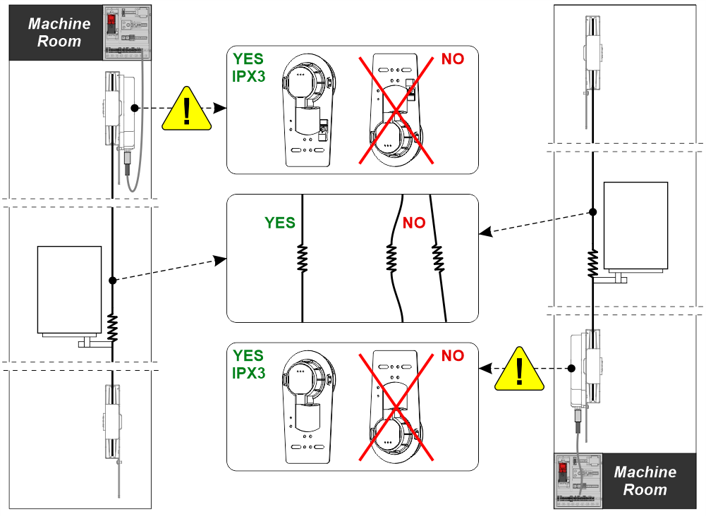
The pulley embedding the Encoder must be installed in the top of the shaft or in the pit, close to the machine room.
System components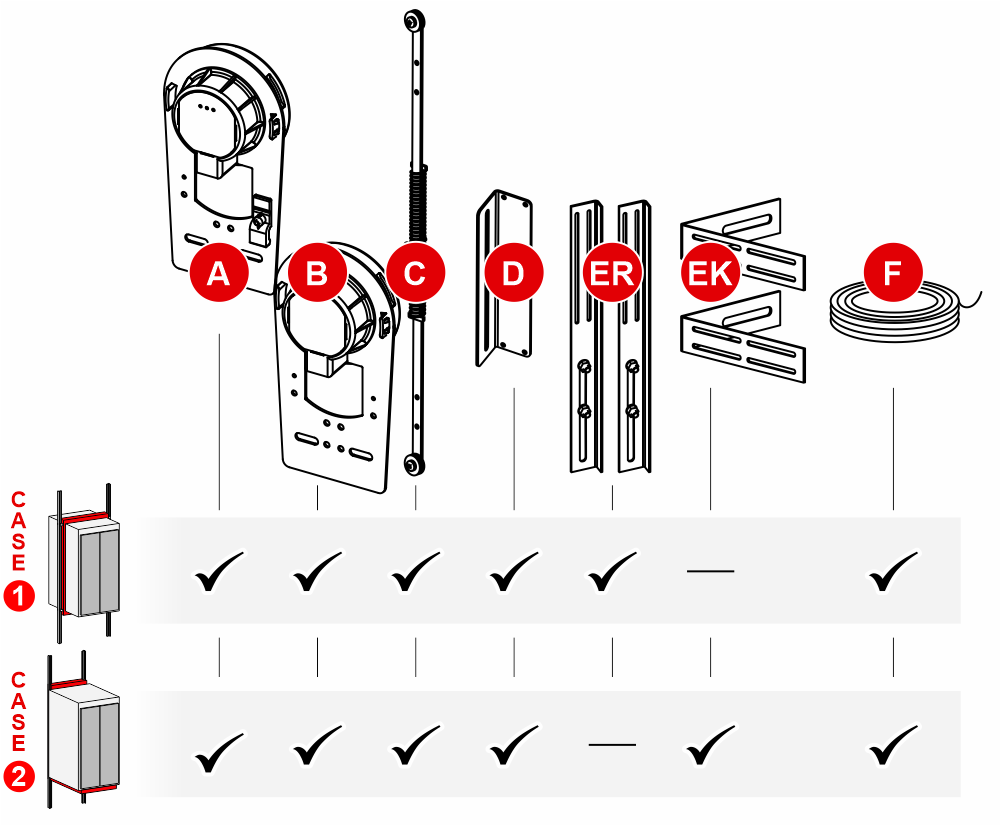
Case 1 : Elevators with frame mechanics
Case 2 : Elevators with backpack mechanics
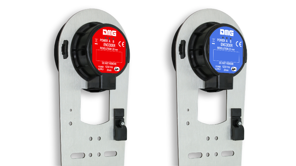
A) – It is the Encoder pulley that contains the electronic card. It can have 2 resolutions:
– 1.25 mm (100 PPR) for the red labeled encoder: To be used with the Pitagora 4.0 controller starting from firmware version 3.0.2
– 2.5 mm (50 PPR) for the blue labeled encoder: To be used with the V3 / Musa / Pitagora 4.0 controllers up to Firmware Y version
C) – The spring tensioner can also be mounted on the top of cabin as needed.
Mounting
Mounting depends on the mechanics of the installation.
Case 1 – Elevators with frame mechanics
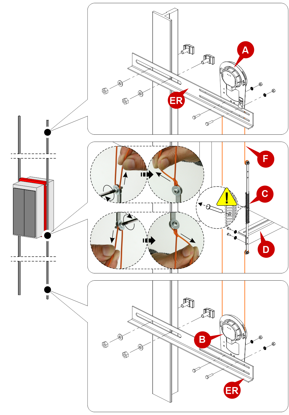
C) – The spring tensioner can also be mounted on the top of cabin as needed.
![]() Remove the retainer only after the installation is complete.
Remove the retainer only after the installation is complete.
In case of replacement on old systems, it will be necessary to untie the old rope and re-tension it after assembling the new encoder.
Case 2 – Elevators with backpack mechanics
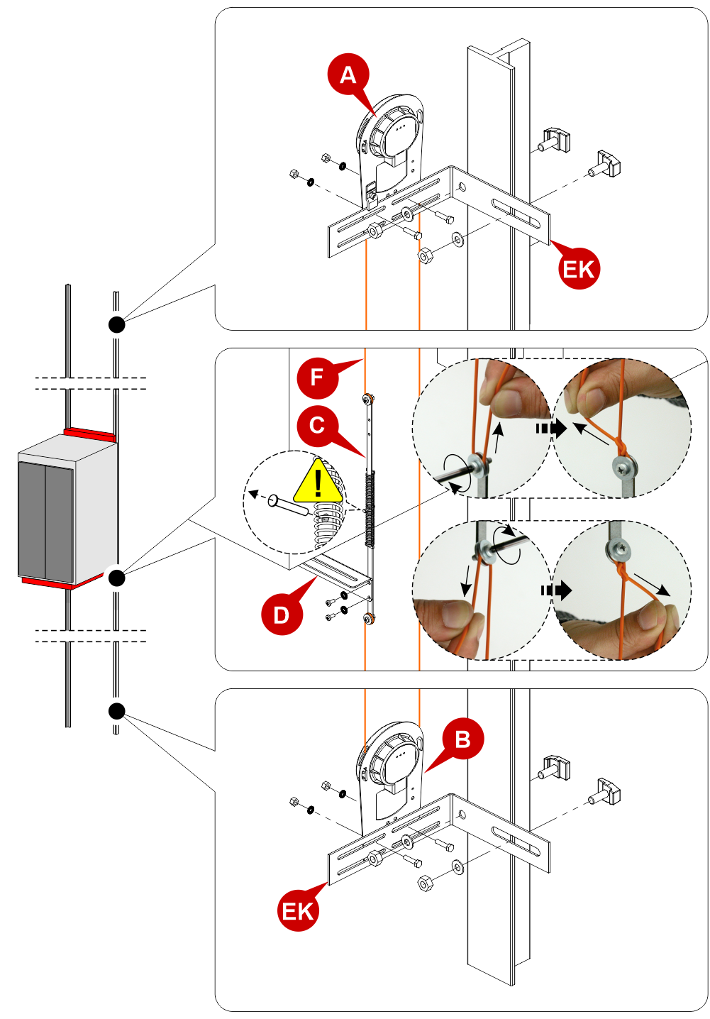
C) – The spring tensioner can also be mounted on the top of cabin as needed.
![]() Remove the retainer only after the installation is complete.
Remove the retainer only after the installation is complete.
In case of replacement on old systems, it will be necessary to untie the old rope and re-tension it after assembling the new encoder.
Wirings
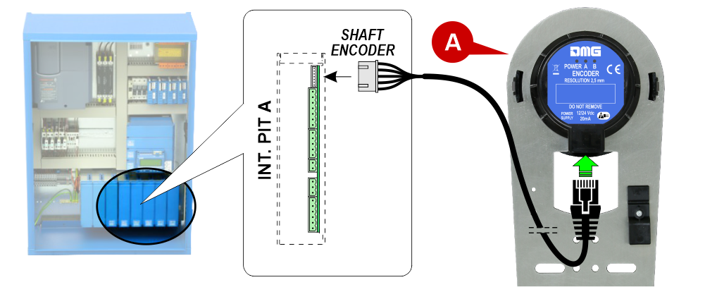
Connection to Pitagora 4.0 controller
– Starting from firmware version 3.0.2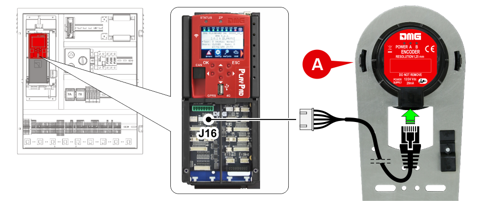 A) – Encoder with 1.25 mm resolution
– Up to firmware version 3.0.1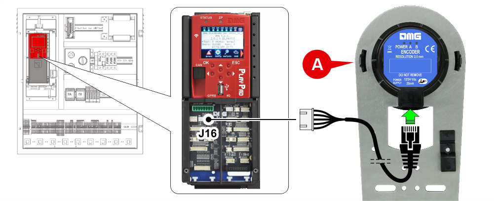 A) – Encoder with 2.50 mm resolution
Connection to existing MUSA / PLAYBOARD V3 controllers
A) – Encoder with 2.50 mm resolution
You can replace the existing rope encoder with the new magnetic encoder (2,50 mm resolution).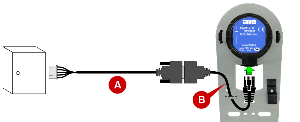
Just leave the existing cable (A) and connect it to the new encoder by means of an adapter cable (B).
After replacing the encoder, check:
- The correct direction of rotation in inspection mode (up movement, increase in mm, down movement, decrease in mm). If necessary, change the direction of rotation from the controller by following these instructions:
- Set the panel in Temporary operations (Configuration menu -> Temporary operations -> Yes);
- Change the rotation in the System Positioning menu -> Positioning System -> clockwise/counterclockwise encoder;
- Remove the Temporary operations (Configuration menu -> Temporary operations -> No).
- Check the correct alignment of the car on all floors. If necessary, adjust the stopping accuracy from the controller in the System Positioning menu -> Floor position.
 If you replace an old DMG optical rope encoder with the current magnetic reading one (50 PPR / 2.5 mm), there is no need to re-learn the positions.
PIN OUT JST 7 poles connector

Diagnostics LED

POWER: If the LED is on, the encoder is powered.
A/B: Status of encoder outputs. With the lift car stationary there is no change in the status of these LEDs (they can be both ON and OFF); with the lift car in motion the LEDs will both be ON.
Download
| Reference | Version | Link |
|---|---|---|
| 1.0 (current version) | Download PDF (English) | |
| Mounting upgrade for old system and Connection on existing installations | 1.1 (current version) | Download PDF (English) |


