(v 2.5)

Safety and usage cautions
Before installing our products, we recommend you to consult the section about safety and usage cautions at the link below

Parts identification

CES006L – Control unit for electronic key
CCME – Electronic key MASTER (red)
CCUE – Electronic key USER (green)
CCBE – Electronic Key of BACKUP (black)
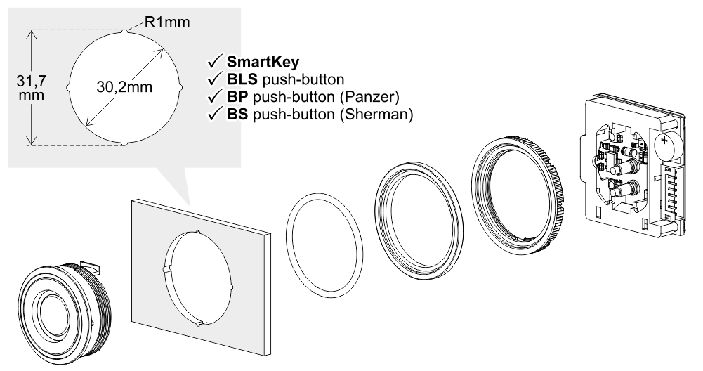
Cut-out for: BM Macro push-button (Ø 32mm)
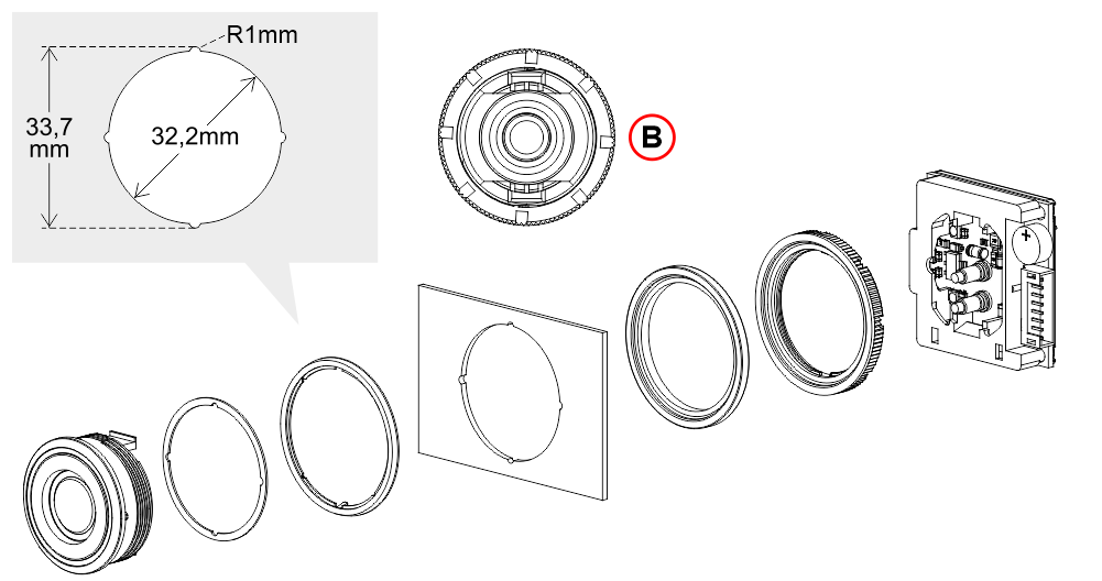
B) Since there is no anti-rotation, position the electronic key reader device as shown in the rear view.
Cut-out for: BM Macro push-button (Ø 35mm)
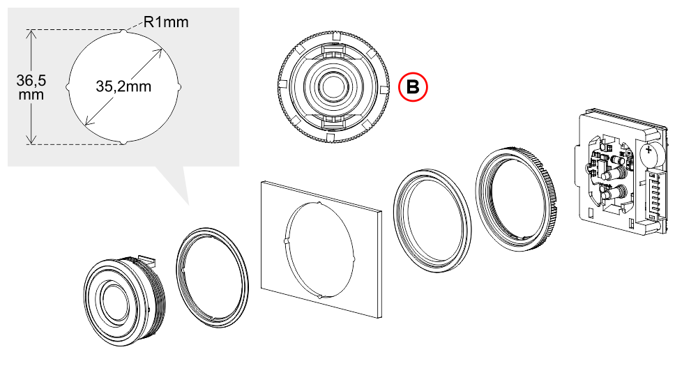 B) Since there is no anti-rotation, position the electronic key reader device as shown in the rear view.
Principle of operation
Each control unit (CES006L) can memorize up to 124 electronic keys (4 Master CCME + 120 User CCUE) and each single key can be memorized on several control units.
The Master key CCME is required for programming and resetting the User keys CCUE.
The Backup key CCBE is useful for saving all the User Keys already stored on the control unit.
The unique code present on each key (Master or User) is stored on the control unit in the programming phase.
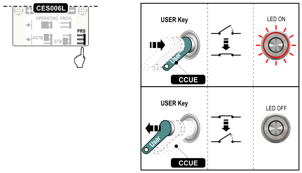
The 3 modes in which you want the User Key to control the calls are described below.

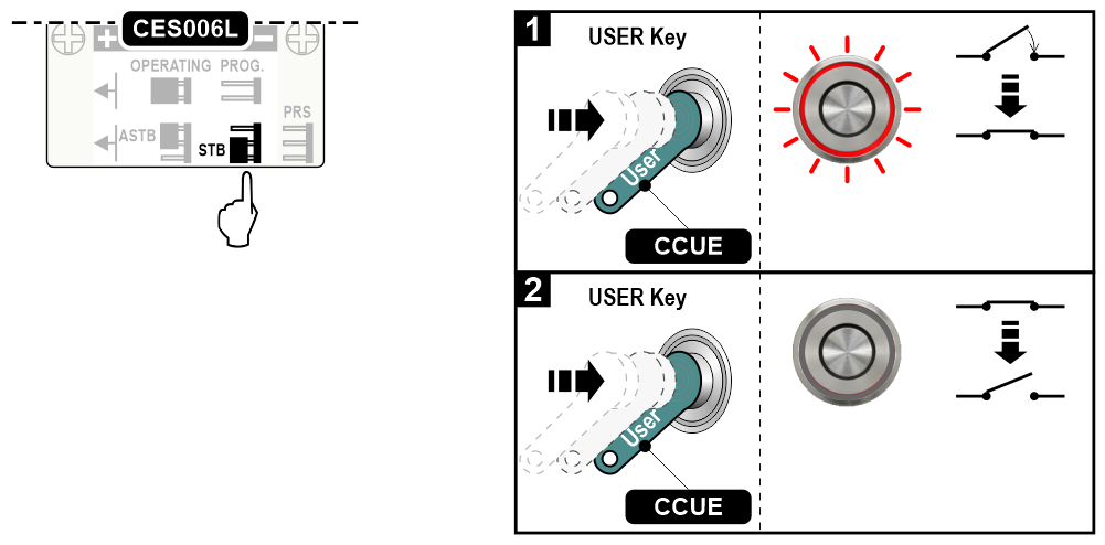
1) – Led always on and closed contact
2) – Slow blinking Led every 5 seconds and open contact
Wiring Instructions
Power supply: 12V/24Vdc +/10% (*) – Imax 0,5A
Output: 1C NO – 0,5A 24V

(*) In case of rectified supply voltage (not filtered) the maximum value is 21V.
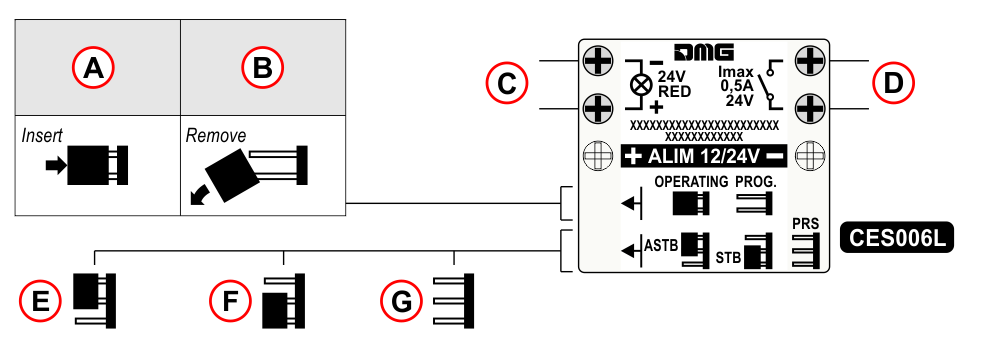
A) – Operative mode
B) – Programming mode
C) – Illuminazione
D) – Contact
E) – Astable mode
F) – Stable mode
G) – Constant pressure (man present)
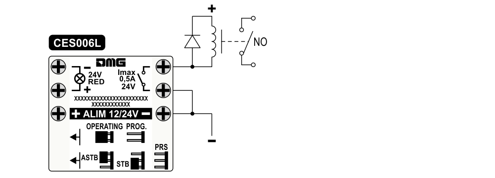
For loads greater than those indicated in the electrical characteristics, use an external relay as shown in the diagram above.
Programming
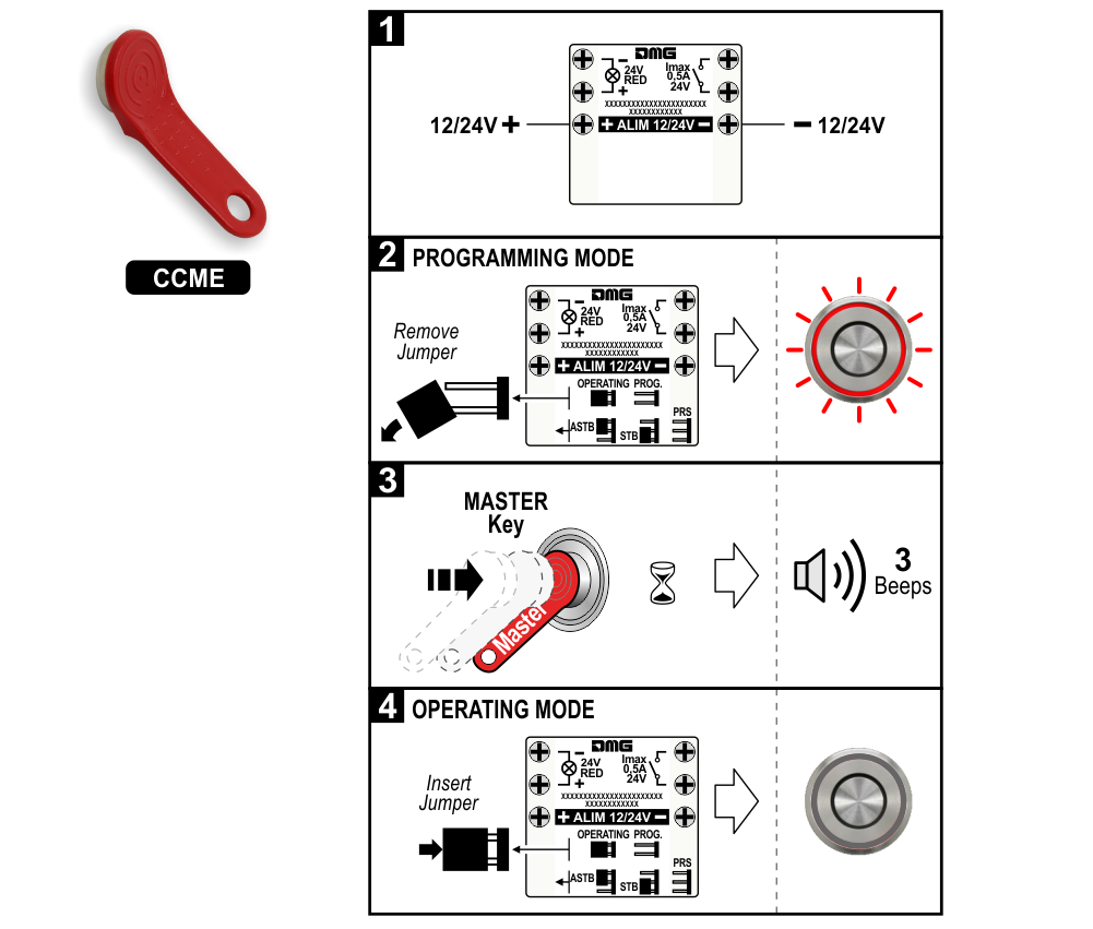
1) – Power supply the device.
2) – Programming mode (Blinking Led every second).
3) – Approach the Master key to the control unit.
4) – Operative mode (Slow blinking Led every 5 seconds).
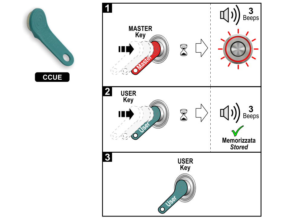
1) – Approach the Master key to the control unit and wait for the Led to flash quickly every half second.
2) – Approach the User key to the control unit within 10 seconds to memorize it.
3) – Repeat step 2 for all User Keys to be memorized (max 120) or allow the 10 seconds to expire to exit the programming phase.
The backup does not transfer the Master key programming. After completing the data transfer from the Backup key to the control unit, and before reinserting the PROG jumper, proceed with the programming of the Master key(s) as described in the section “Master Key Programming (CCME)
– Data acquisition and saving
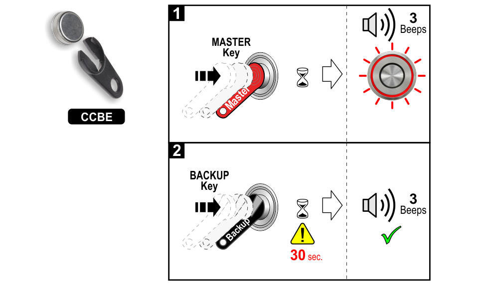 1) – Approach the Master key to the control unit and wait for the Led to flash quickly every half second.
2) – Approach the electronic Backup key to the control unit within 10 seconds and wait about 30 seconds before the beep.
– Data entry
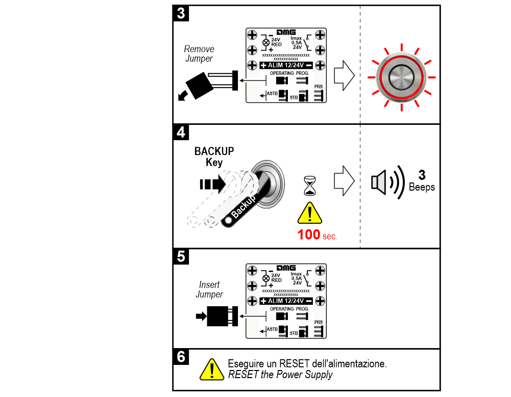
3) – Blinking Led every second.
4) – Approach the electronic Backup key to the control unit and wait about 100 seconds before the beep.
5) – Insert the jumper for the operative mode.
6) – Reset the power supply.
Reset
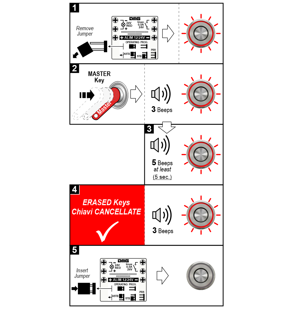
1) – Blinking Led every second
2) – Led always on
3) – Led flashing quickly every half second
4) – Erased electronic keys (Blinking Led)
5) – Slow blinking Led every 5 seconds
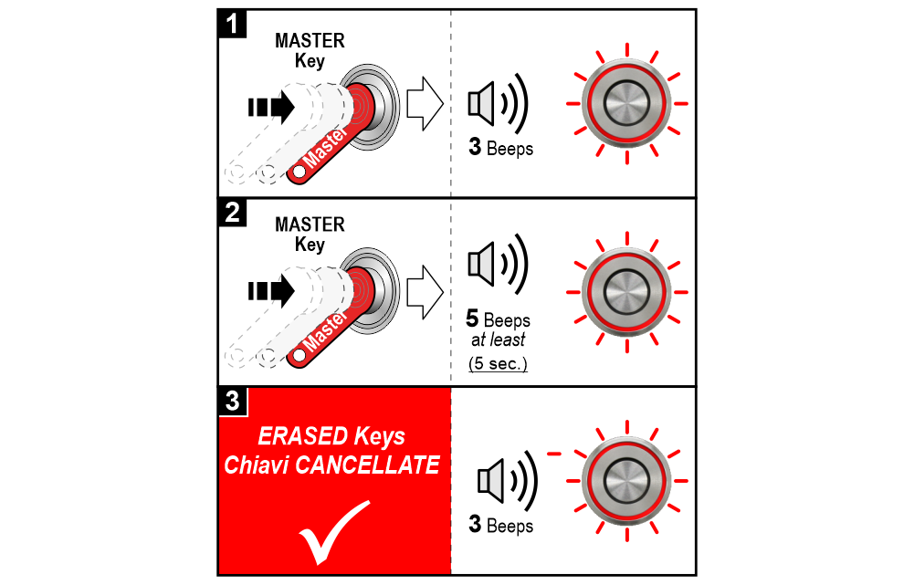
1) – Led always on
2) – Led flashing quickly every half second
3) – Erased electronic keys (Blinking Led)
Download
| Reference | Version | Link |
|---|---|---|
| 2.5 (current version) | Download PDF (English) | |
