(v 2.0)
Safety and usage cautions
Before installing our products, we recommend you to consult the section about safety and usage cautions at the link below

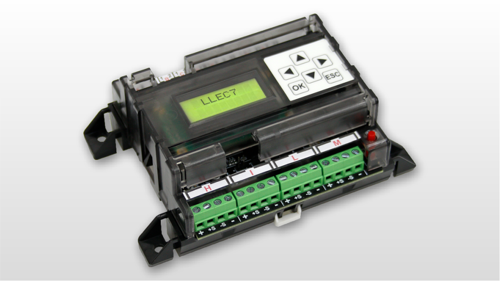
Main features
- 3 relays thresholds + analog output.
- Automatic compensation of elevator car dynamic load during travel (load locking input).
- It can manage up to 8 individual sensors.
- Adjustable compensation of travelling shaft cable weight.
- Display of the weight and output voltage of each single sensor.
- IPX3 protection through the external cover.
- Device management via Fusion app in local connection.
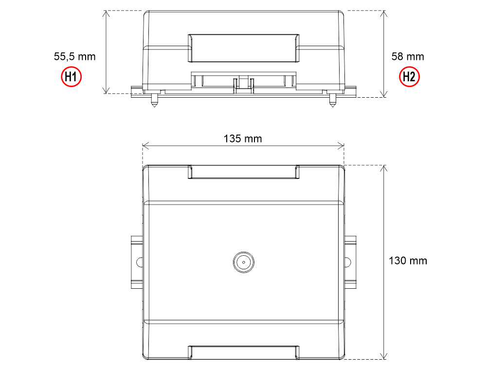
H1 – Fixing with screws
H2 – DIN rail fixing
System components
LLEC7 electronic control unit + external sensors
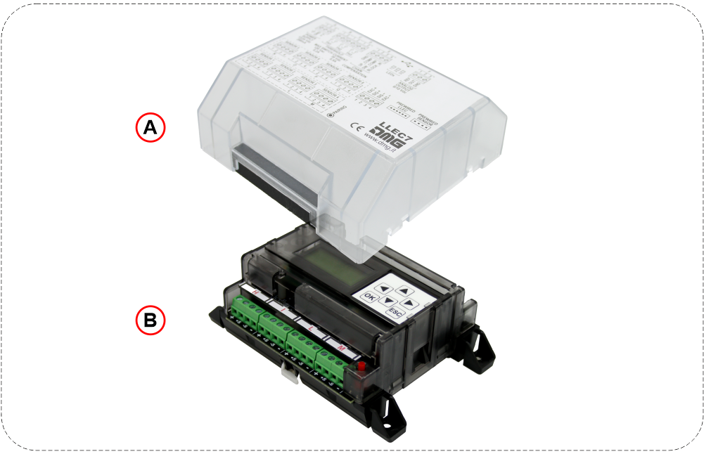
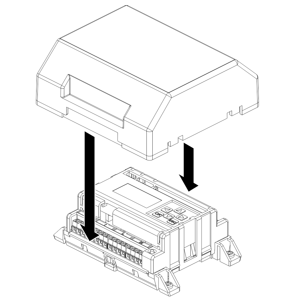
A) – External cover water protection (IPX3)
B) – LLEC7 electronic control unit
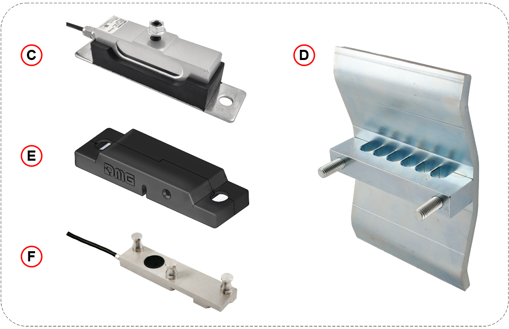
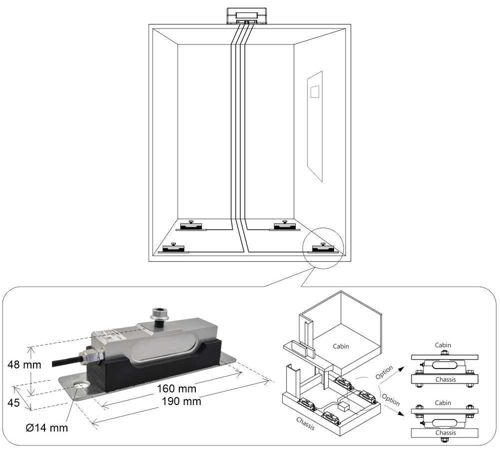
C) – External sensors kit for elevator car bottom (6mt cable)
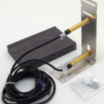
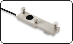
D) – External sensor for ropes
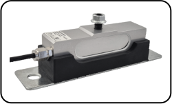
E) – External sensor for car frame
F) – External sensor for single rope
Optional components
 code [AUT.KIT08] – Magnetic sensors (NC)
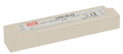 code [EWS.AL212] – Power unit 220V
Management via Fusion APP

The DMG Fusion App, connected via Bluetooth® to the LLEC7, allows you to perform all the procedures present on the device.
It is not necessary to log in.
The mobile App interface is an exact copy of the keyboard and LCD display present on the LLEC7, it allows the installer to carry out all operations without interacting directly with the device
Installation, pairing and use
Download and install the Fusion app using the QR code on the side.

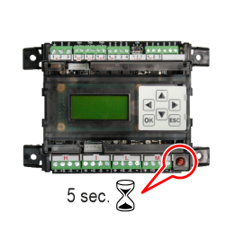 |  | 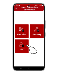 |
| Keep pressed (5 sec.) | You can reach the device locally without logging in (Select “Local Connection”). | Select the type of device to manage (LLEC7). |
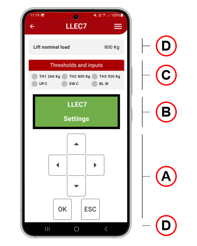
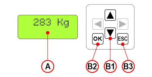
A) Programming keypad
B) LCD display
C) Status and thresholds values / status of the inputs for compensation (UP.C, DW.C) and weight block (BL.W)
D) Also displayed (top and bottom of the screen):
• The values entered during calibration such as Lift load, Number and Type of Sensors, Rope Ratio of the system.
• The HW and SW version of the device.
Installation
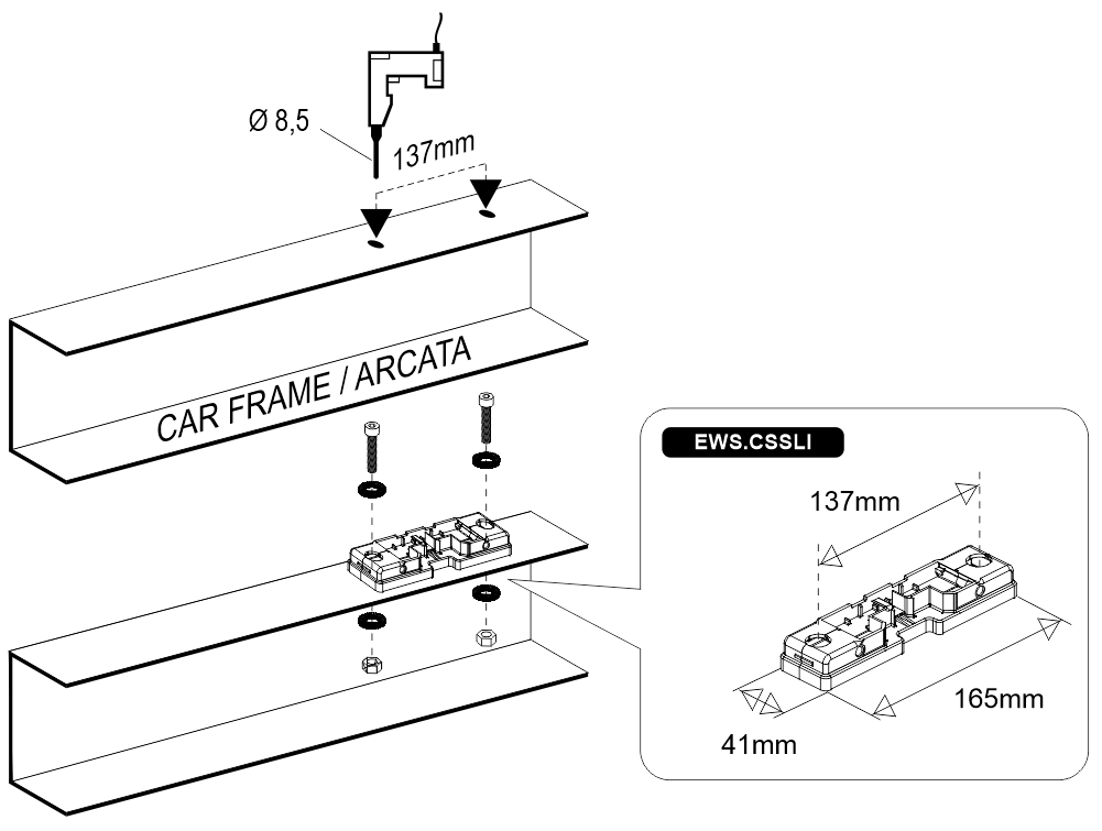
LLEC7 electronic control unit fixing
– Fixing with screws –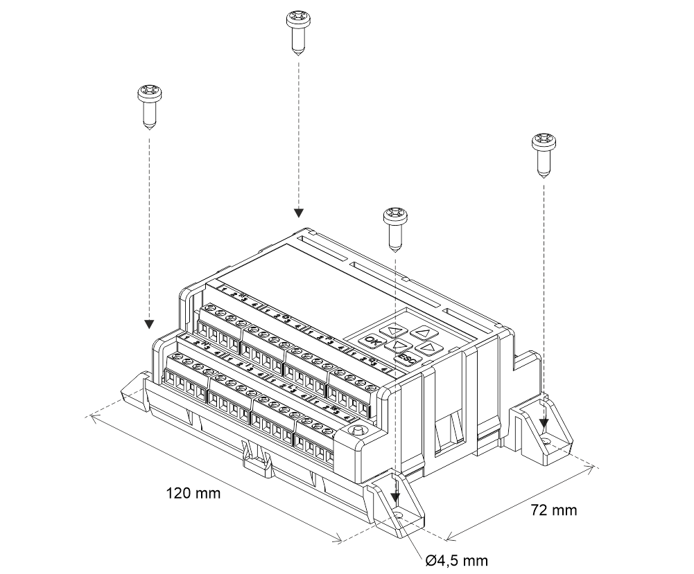
– DIN rail fixing –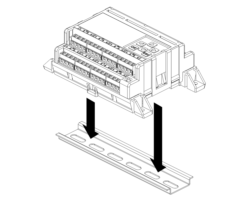
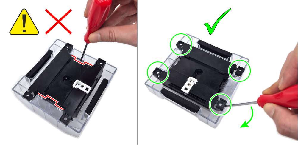
– External protection cover installation –
Installation of car bottom sensors
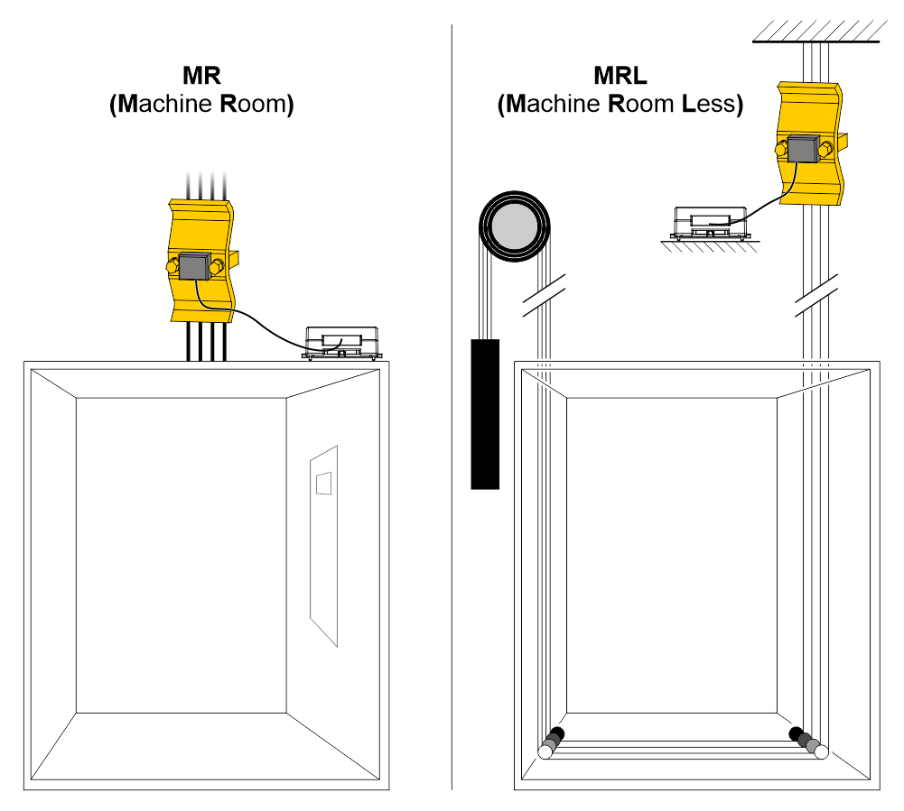
Installation of ropes sensor
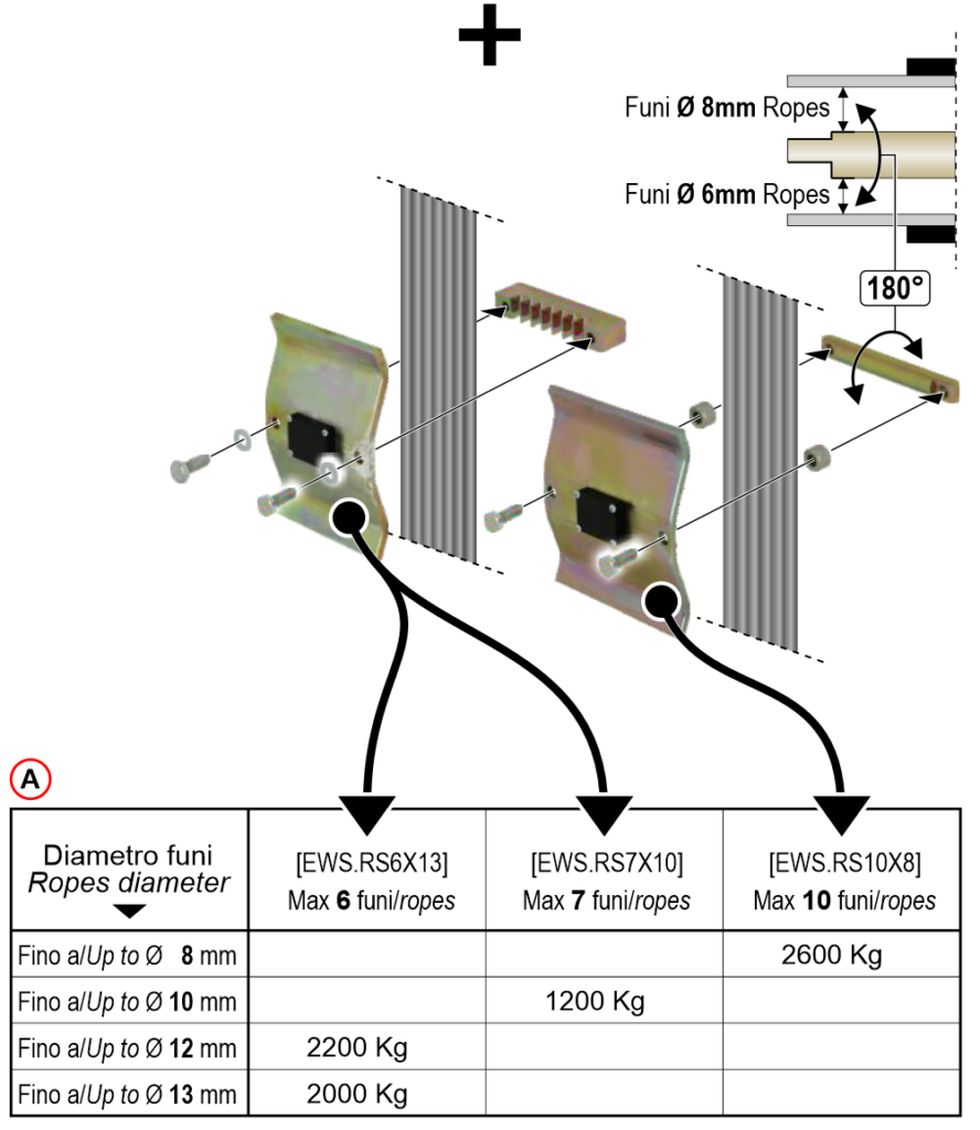
A) – Maximum load table (Mass structure + lift capacity)
In case of lift roping 2:1 (sensor on fixed-ending + pulley) maximum load is doubled.
Installation of single rope sensor
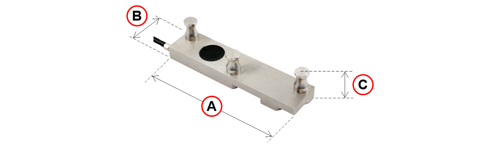
| Sensor nominal load | A | B | C |
| 750 Kg (ropes 6~8mm) | 87 mm | 20 mm | 21,5 mm |
| 1000 Kg (ropes 9~11mm) | 120 mm | 28 mm | 28,5 mm |
| 1000 Kg (ropes 12~15mm) | 132 mm | 36 mm | 33,5 mm |
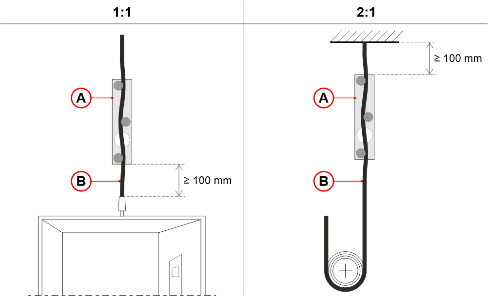
A) Single rope sensor
B) Single rope
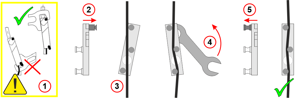
Follow the steps above, making sure to use the wrench provided on the top part of the sensor (4); because on the bottom part, there is a risk of cutting the cable.
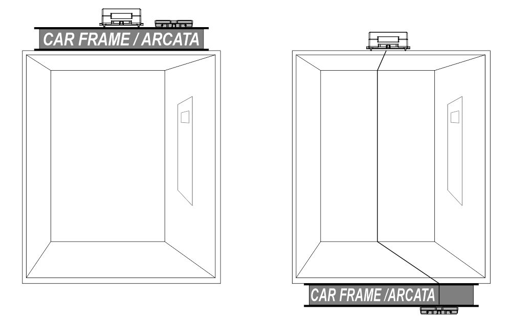
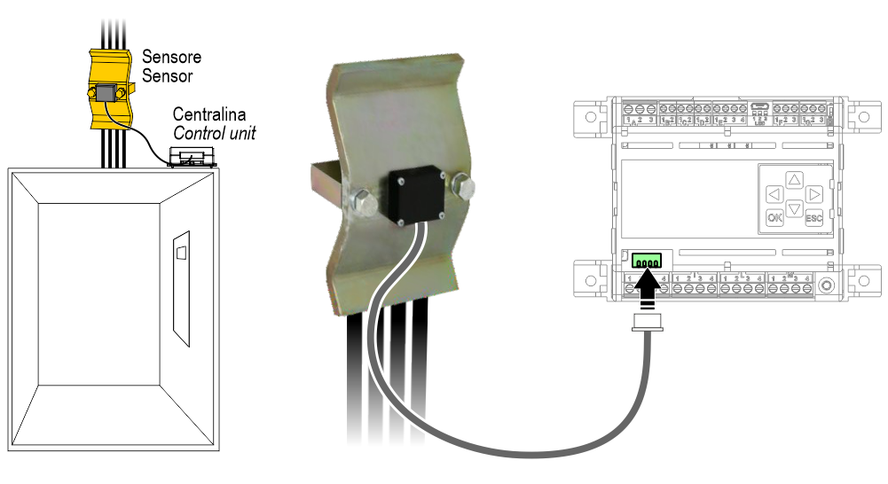
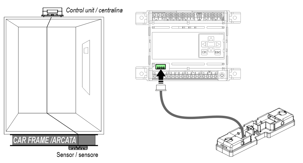
Installation of car frame sensor
Wiring Instructions
General description of the connectors
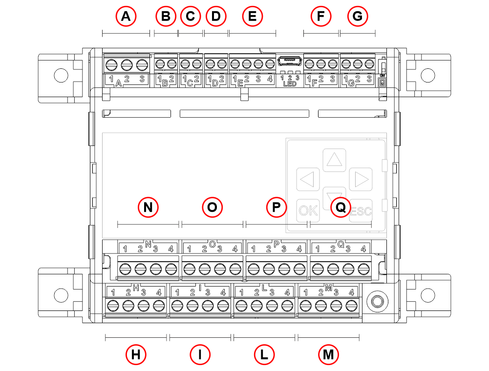
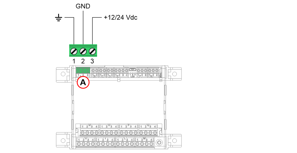
- A – Power supply input
1 – Earth
2 – GND
3 – +12/24 Vdc - B – Threshold 1 (by default 50% of the lift’s nominal load)
1 – COM
2 – NO/NC - C – Threshold 2 (by default 100% of the lift’s nominal load)
1 – COM
2 – NO/NC - D – Threshold 3 (by default 115% of the lift’s nominal load)
1 – COM
2 – NO/NC - E – Travelling cable compensation input / Block weight input
1 – GND
2 – UP_COMP
3 – DW_COMP
4 – BLOC_W - F – Analog output
1 – REF
2 – OUT
3 – GND - G – CAN input (NOT used)
1 – CAN_L
2 – CAN_SHLD
3 – CAN_H - H / I / L / M – Sensor input 1 / 2 / 3 / 4
N / O / P / Q – Sensor input 5 / 6 / 7 / 8
1 – V+ (Excitation +)
2 – S+ (Signal +)
3 – S- (Signal -)
4 – V- (Excitation -)
Power supply input
Connection of thresholds
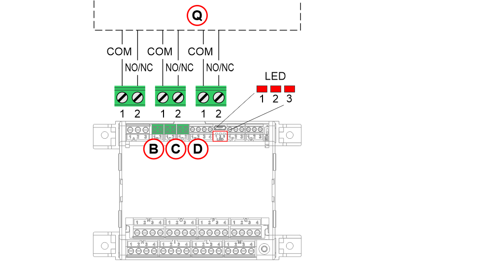
- B) – Threshold 1 (by default 25% of the lift’s nominal load)
1 – COM
2 – NO/NC - C) – Threshold 2 (by default 100% of the lift’s nominal load)
1 – COM
2 – NO/NC - D) – Threshold 3 (by default 115% of the lift’s nominal load)
1 – COM
2 – NO/NC - Q) – Controller
- Threshold LED – The LED lights up if the threshold is active.
LLEC7 + Pitagora 4.0 controller
The connection with the Pitagora 4.0 system takes place via the TOC box located on the top of cabin.
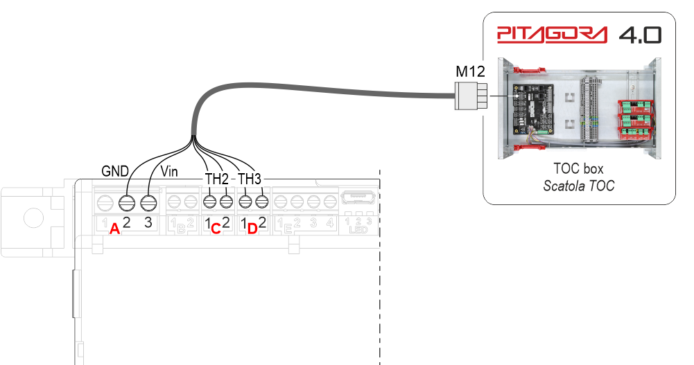
The cable, in addition to supplying power to the LLEC7, also includes the thresholds TH2 (full car 100%) and TH3 (overload 115%).
LLEC7 + NON-DMG controller
The connection shown below supports up to 8 sensors.
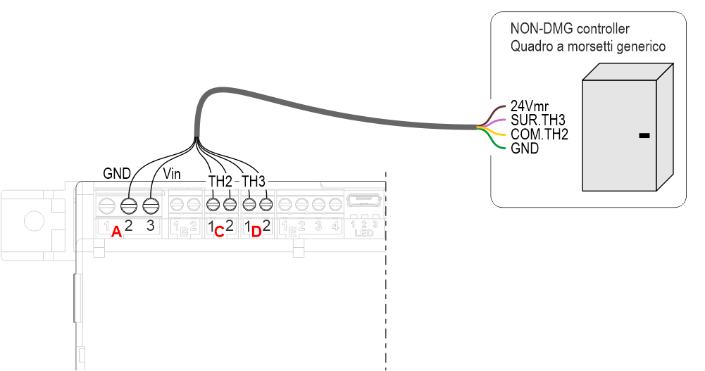
The cable (not supplied with the device,), in addition to supplying power to the LLEC7, also includes the thresholds TH2 (full car 100%) and TH3 (overload 115%).
Connecting sensors for travelling shaft cable compensation
In elevators with heavy cable weight, their compensation is an important step. Important to know:
1) Lift maximum load.
2) travelling cables’ weight per meter.
3) Shaft total length.
Before carrying out this procedure, in addition to the main connections, it is necessary to connect the external position sensor [AUT.KIT08].
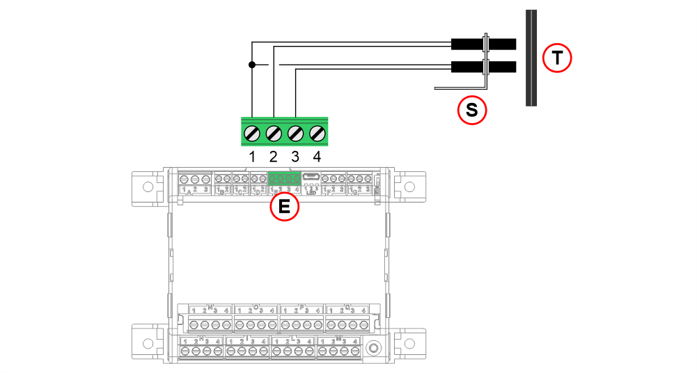
- E – Travelling cable compensation input
1 – GND
2 – UP_COMP
3 – DW_COMP
4 – X (See the weighing lock function) - S – Position sensors on the top of cabin
- T – 1 Magnet at each floor
Connection of the weighing lock function
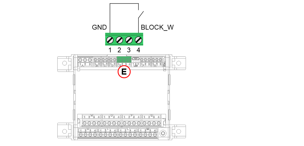
- E – Block weight input
1 – GND
2 – X
3 – X
4 – BLOCK_W

The input must not be connected directly to the safety circuit.
Connection of the elevator car bottom sensors
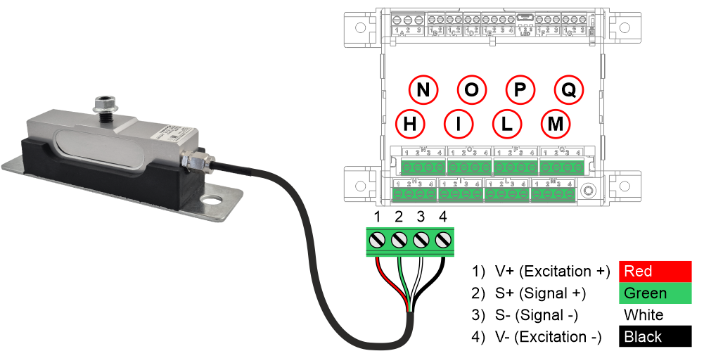
- H / I / L / M – Sensor input 1 / 2 / 3 / 4
N / O / P / Q – Sensor input 5 / 6 / 7 / 8 (only with optional expansion board)
1 – V+ (Excitation +) connected to the red cable
2 – S+ (Signal +) connected to the green cable
3 – S- (Signal -) connected to the white cable
4 – V- (Excitation -) connected to the black cable
The length of the connection cable is 6 m.
Connection of ropes’ sensor
Connection of the single rope sensor
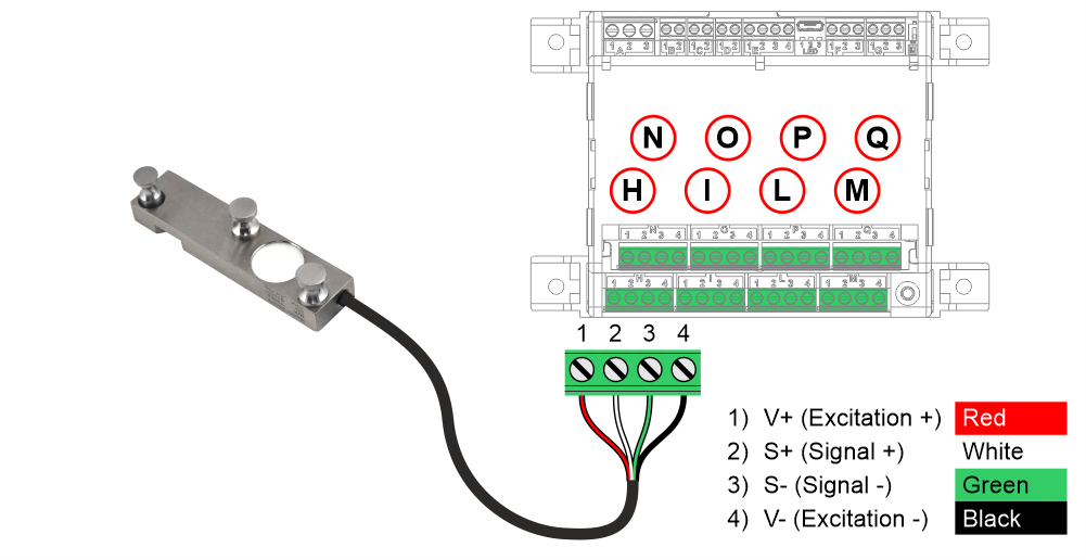
- H / I / L / M – Sensor input 1 / 2 / 3 / 4
N / O / P / Q – Sensor input 5 / 6 / 7 / 8 (only with optional expansion board)
1 – V+ (Excitation +) connected to the red cable
2 – S+ (Signal +) connected to the white cable
3 – S- (Signal -) connected to the green cable
4 – V- (Excitation -) connected to the black cable
Connection of car frame sensor
Programming
Display after calibration
A) Current weight detected in the elevator car.
Programming keypad
B1) Browse options at current level.
B2) Access the menu and confirm selection.
B3) Exit the current level and return to the previous level.
Programming menu map
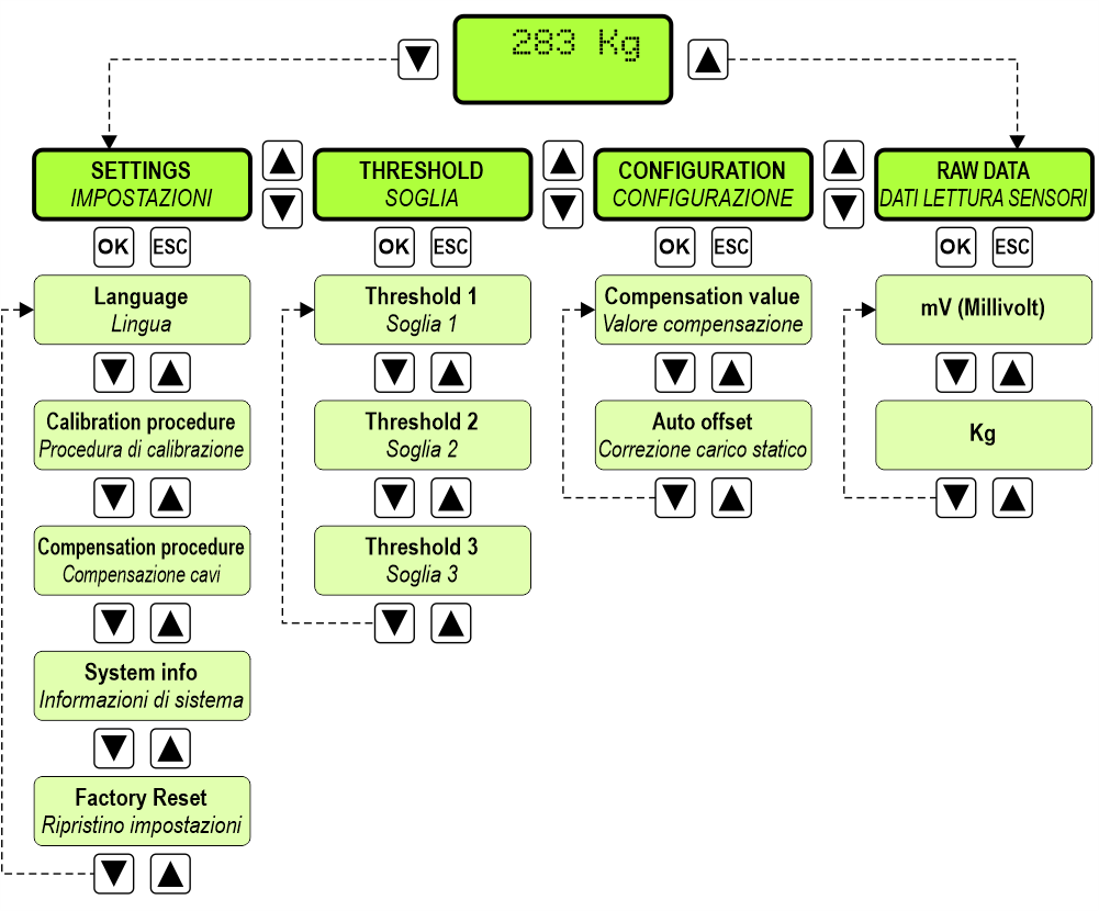
If the calibration procedure has not yet been performed, the main menu screen will display the following message:

Calibration procedure
- English
- Italian
- German

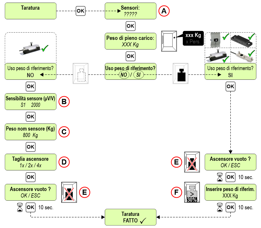
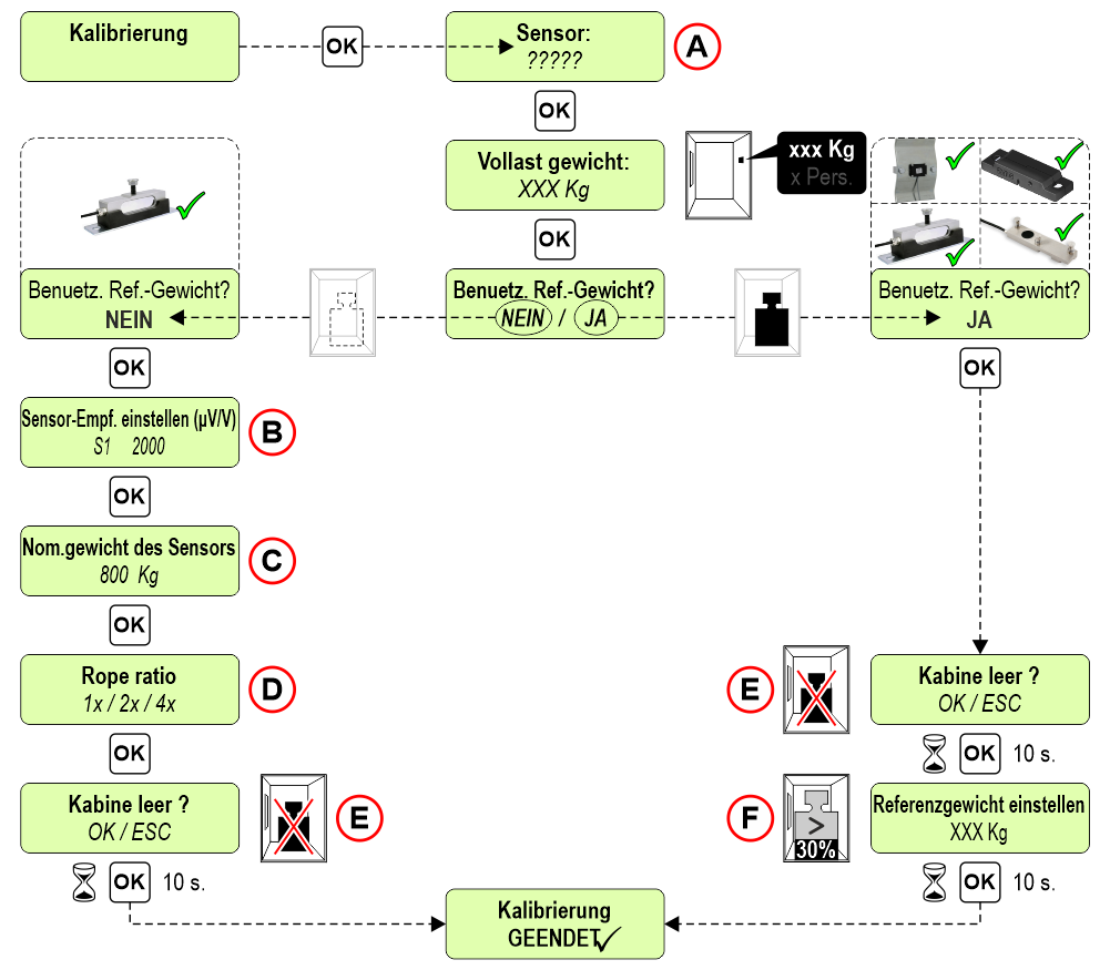
A) For car bottom sensors or single rope sensors, the quantity is also requested.
B) Enter the sensitivity of each sensor (see the label on the sensor).
C) Enter the sensor nominal load.
D) Enter the rope ratio of the system (if it is requested).
E) To carry out the calibration the car must be empty
F) Insert a weight at least 30% of the capacity in the center of the car; the greater the weight entered, the greater the calibration accuracy.

Check the activation of the overload threshold and the correspondence between the real weight in the car and that indicated on the LLEC7 device (± 5%).
Travelling cable compensation procedure
Before carrying out this procedure, calibrate the system and connect the AUT.KIT08 magnetic sensors kit (§ Connecting sensors for travelling shaft cable compensation).
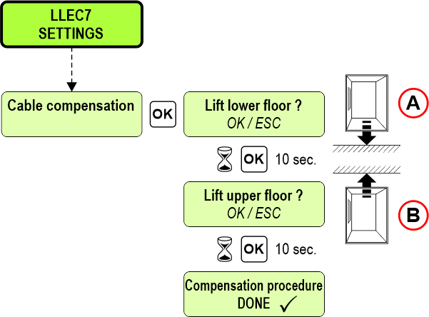
A) Move the car to the lower floor.
B) Move the car to the upper floor.
Setting thresholds values
For each threshold it is possible to set the value (Kg) and the type of contact (Normally Open / Normally Closed).
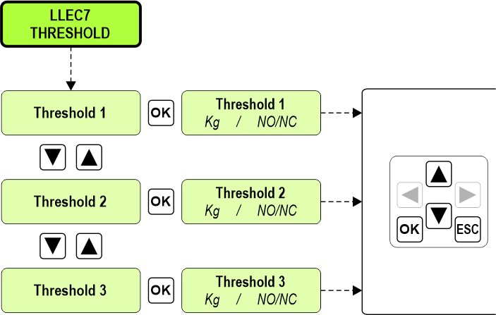
Default values:
Threshold 1 : 25% of the lift’s nominal load / Normally Open
Threshold 2 : 100% of the lift’s nominal load / Normally Open
Threshold 3 : 115% of the lift’s nominal load / Normally Open
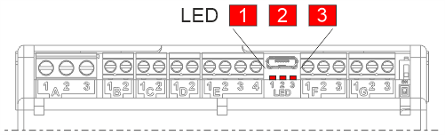
The LED lights up if the threshold is active.
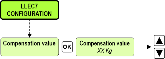
Manually setting of the travelling shaft cable compensation value
It is possible to manually modify the value detected in the travelling cable compensation procedure.
Display of the weight and the voltage of each single sensor
Useful feature for:
• Check the weight distribution inside the cabin
• Check whether there are ropes with different tensions on the system
• Check which sensor is not working
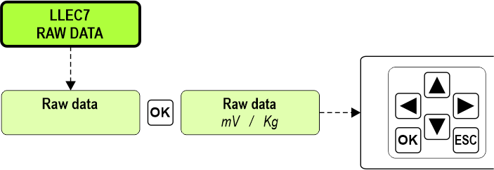
Display the weight (Kg) and the voltage in millivolts (mV) of each single sensor.
.
Datasheet

| LLEC7 electronic control unit | |
|---|---|
| Voltage | 12/24V DC |
| Max absorption | 200 mA |
| Relays output 1/2/3 | 1A, 30V DC (Resistive load) |
| Load locking input | Dry contact |
| Operating temperature | -10°c ~ +50°c |
| Car bottom sensor | |
|---|---|
| Range | 800 Kg |
| Input impedance | 1030 ± 10 Ω |
| Output impedance | 1000 ± 2 Ω |
| Insulation Impedance | ≥ 5000M Ω |
| Safe Overload | 150% F.S |
| Ultimate Overload | 200% F.S |
| Temperature Effect | ± 0,02% F.S/10°C |
| Operation Temperature | -30°c ~ +70°c |
| Protection Class | IP67 / IP68 |
| Cable lenght | 6 mt |
| Single rope sensor | |
|---|---|
| Nominal load | 750 Kg (ropes 6~8mm) / 1000 Kg (ropes 9~11mm) / 1000 Kg (ropes 12~15mm) |
| Rated output | 0,5 ~ 2,0 ± 0,1 mV/V |
| Input impedance | 350 ± 20 Ω |
| Output impedance | 350 ± 3 Ω |
| Insulation Impedance | ≥ 5000M Ω /100VDC |
| Recommended excitation | 3,3 V |
| Max excitation | 15 V |
| Safe Overload | 150% F.S |
| Ultimate Overload | 200% F.S |
| Temperature Effect | ± 0,5% F.S/10°C |
| Operation Temperature | -20°c ~ +80°c |
| Protection Class | IP66 |
| Cable lenght | 2 mt |
Troubleshooting
| Problem | Solution |
|---|---|
| The device reports an error at the end of the calibration procedure. | Check the correct connection of the sensors. |
| The device reports an error at the end of the compensation procedure. | Check the correct connection of the magnetic sensors. |
| The weight detected in the car does not seem correct. | Check all the sensors, viewing the weight and output voltage. (see the “Raw Data” menu). |
Usage tips
- On new installations it is advisable to repeat the calibration procedure after some time, since the decrease in friction of the lift could distort the correct functioning of the LLEC7 device.
- It is advisable to never change the length of the sensor cables, as this could influence their factory preset sensitivity.
- Before carrying out the calibration procedure, check that the car is free from any friction with the guides.
- If dummy car bottom sensors are used, the accuracy of the weighing is not guaranteed.
Download
| Reference | Version | Link |
|---|---|---|
| 1.2 | Download PDF (English) | |
| Connection with the Pitagora 4.0 controller | 1.3 | Download PDF (English) |
| Updated commercial codes | 1.4 | Download PDF (English) |
| Disassembly instructions | 1.5 | Download PDF (English) |
| connection of magnetic sensors for travelling cable compensation | 1.6 | |
| Version with single rope sensor | 1.7 | Download PDF (English) |
| Car frame sensor position | 1.8 | Download PDF (English) |
| LLEC7 + Pitagora 4.0 controller | 1.9 | Download PDF (English) |
| Ropes sensor codes | 2.0 (current version) |