(v 1.1)

Safety and usage cautions
Before installing our products, we recommend you to consult the section about safety and usage cautions at the link below.

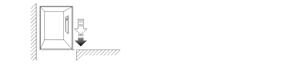
Mounting
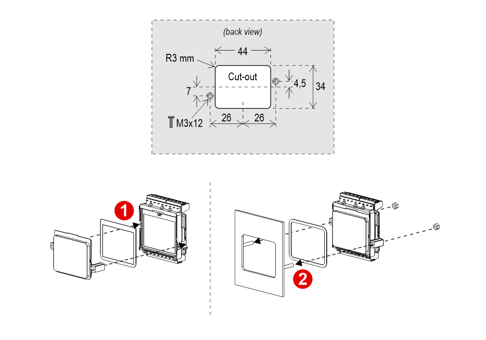
Flush Mounting (back mounting)
With welded pins on 1,5÷2 mm pushbutton panel
With D13 Screen (frontal mounting)
Frontal mounted on 0,7/2 mm pushbutton panel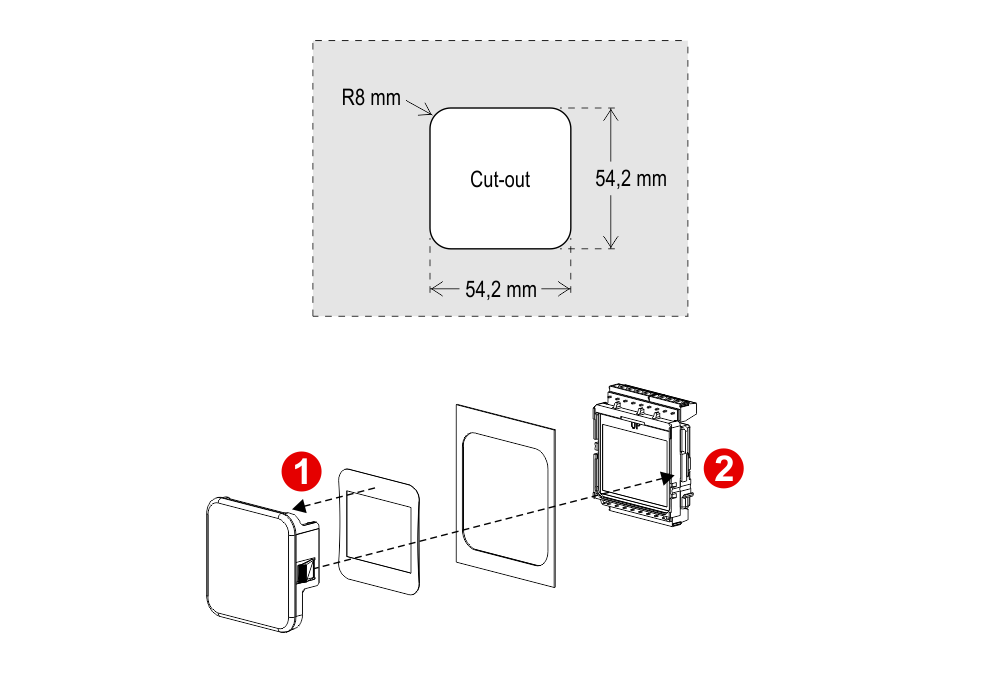
With DZ1 Screen (frontal mounting)
Frontal mounted on 0,7/2 mm pushbutton panel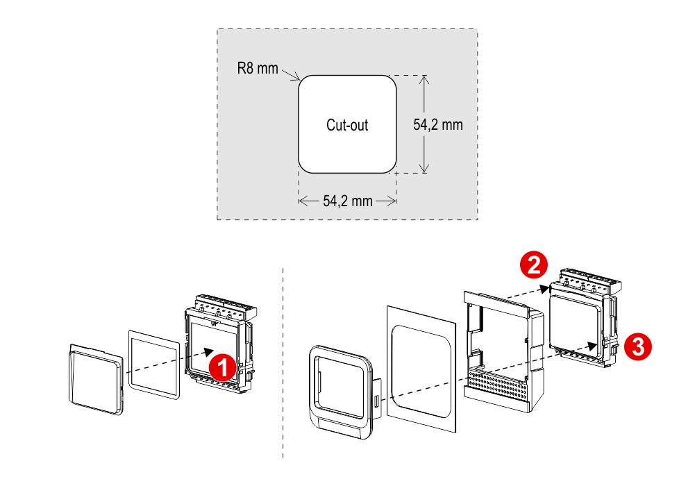
Wiring Instructions
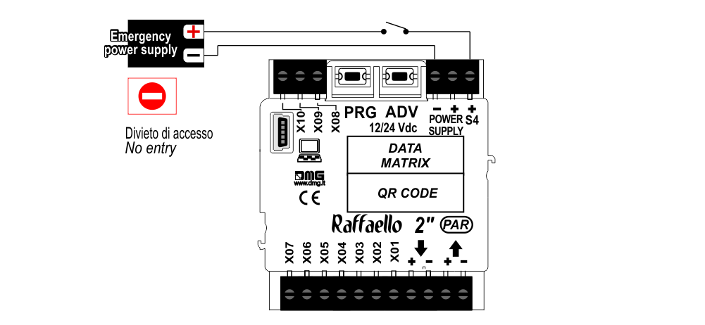
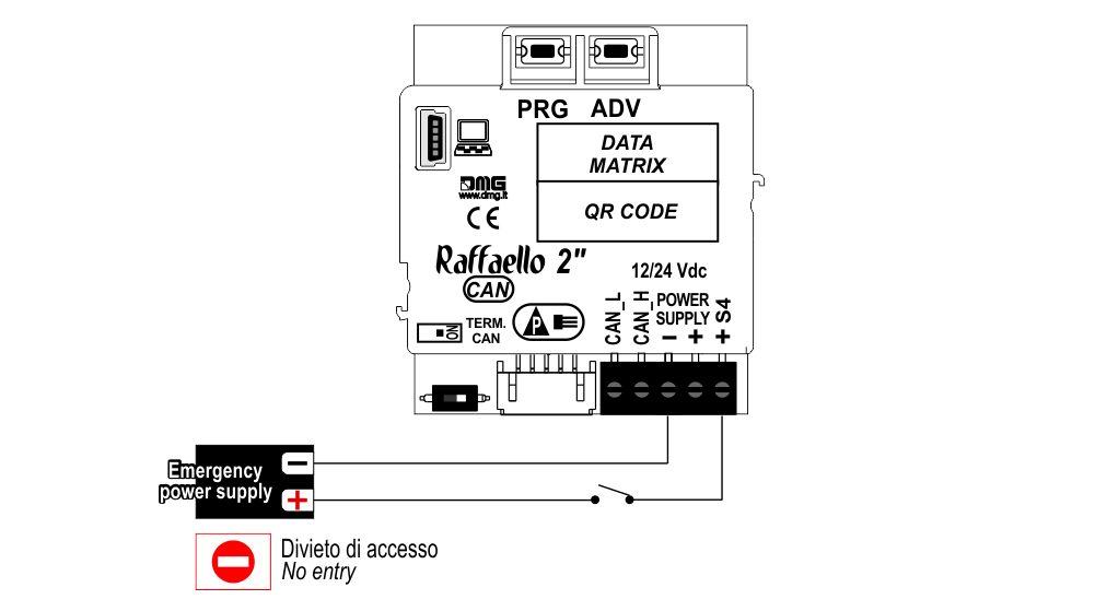
POSITION & DIRECTION Input Wiring
Pitagora 4.0
DMG
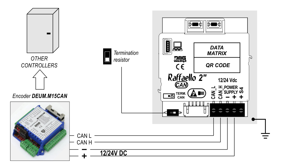
CAN serial protocol
FLOOR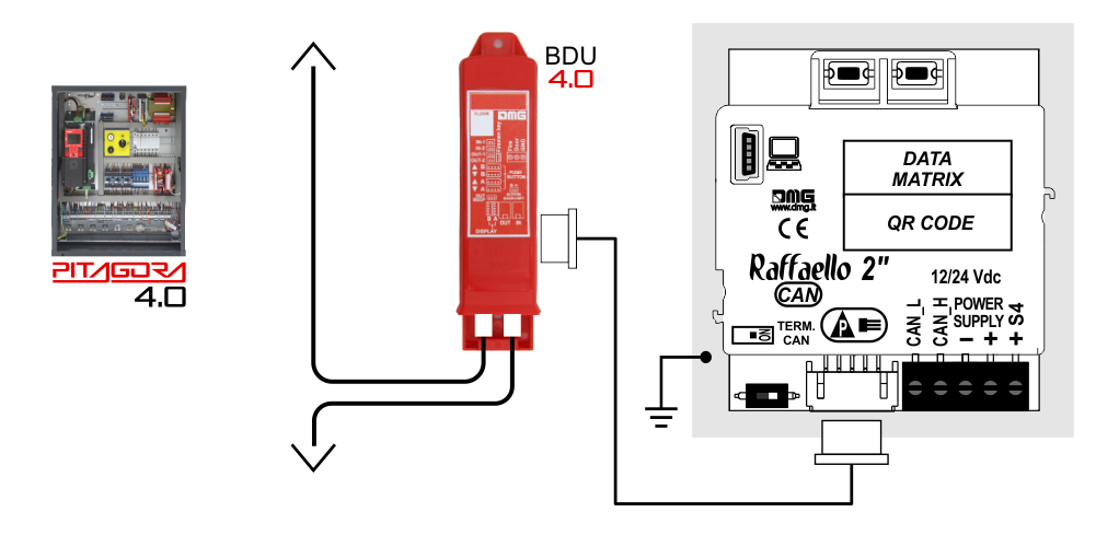
DMG
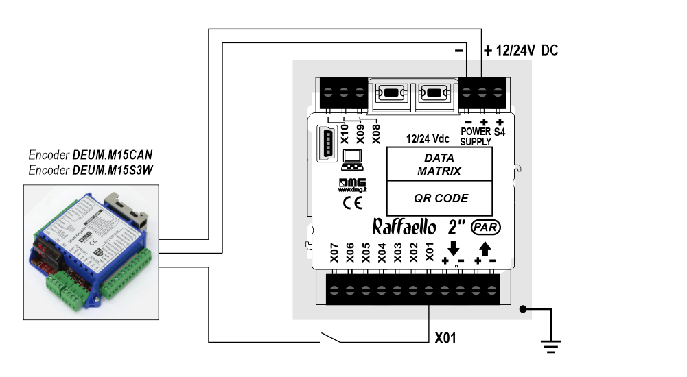
3-wires serial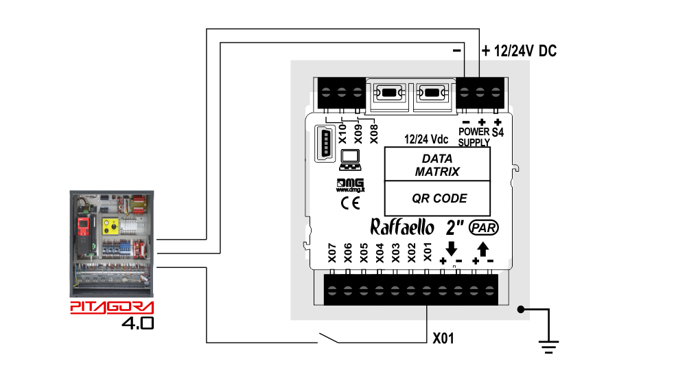
CAN serial protocol
FLOOR
DMG
3-wires serial
Encoder DEUM
 For more details please refer to the Encoder DEUM support page.
DMG
CAN serial protocol
DMG
3-wires serial
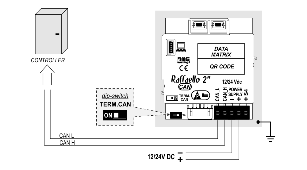
Other Controllers
Proprietary CAN protocol
1 Wire / Floor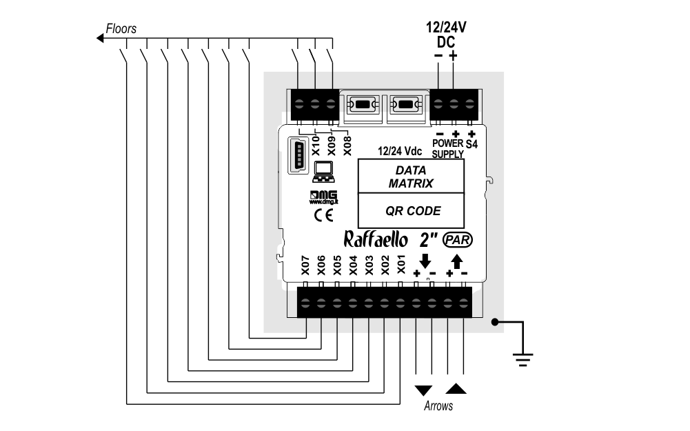
 10 floors max.
1 Wire / Segment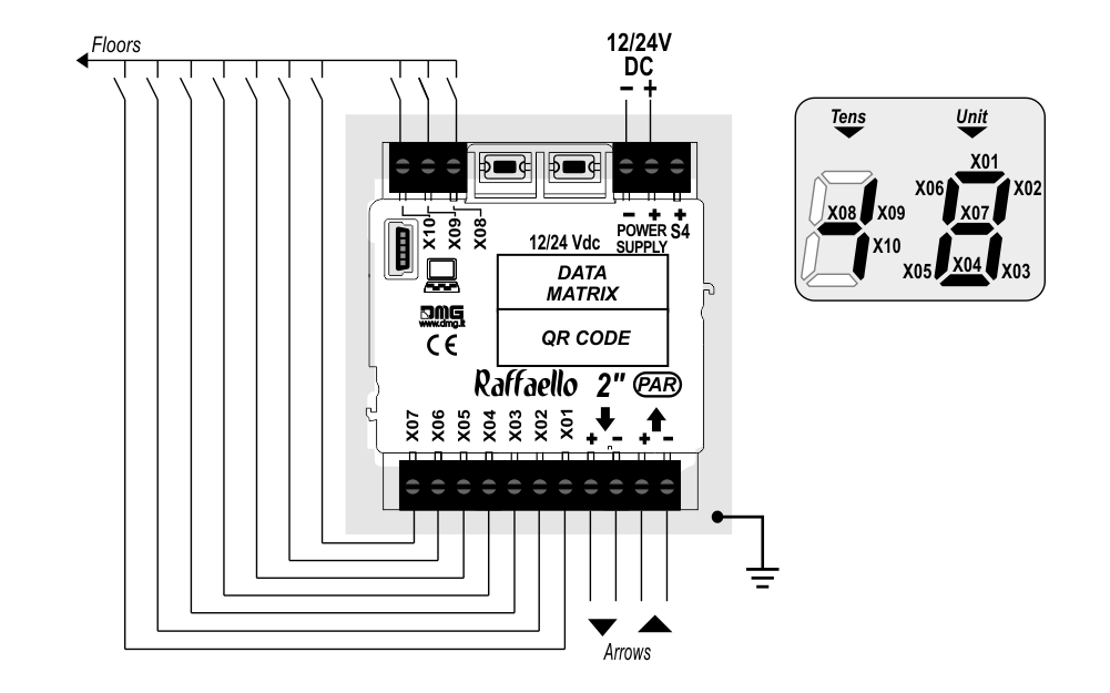 29 floors max. (-9, 0, 19)
Gray / Binary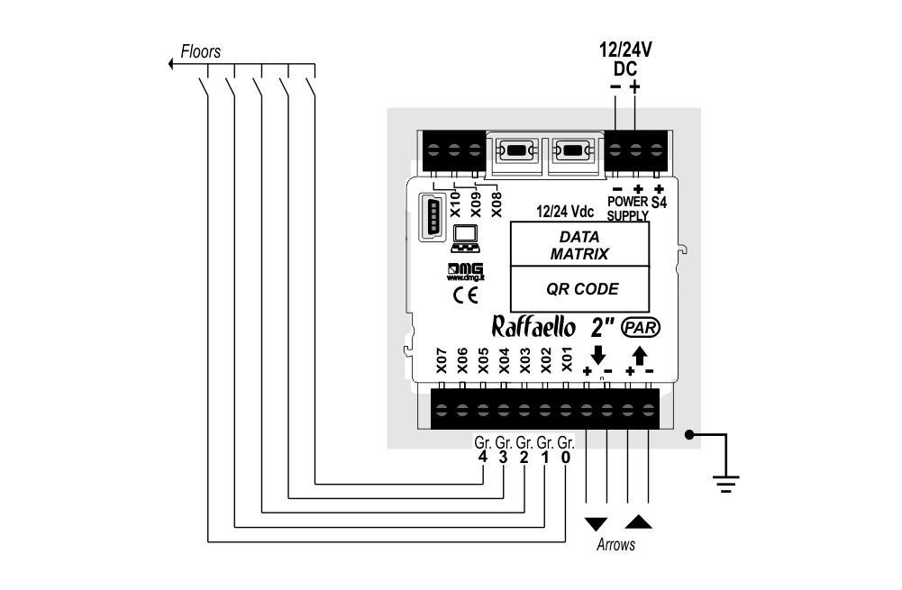 72 floors max. (-9, 0, 62)
TKE/MEA/Autinor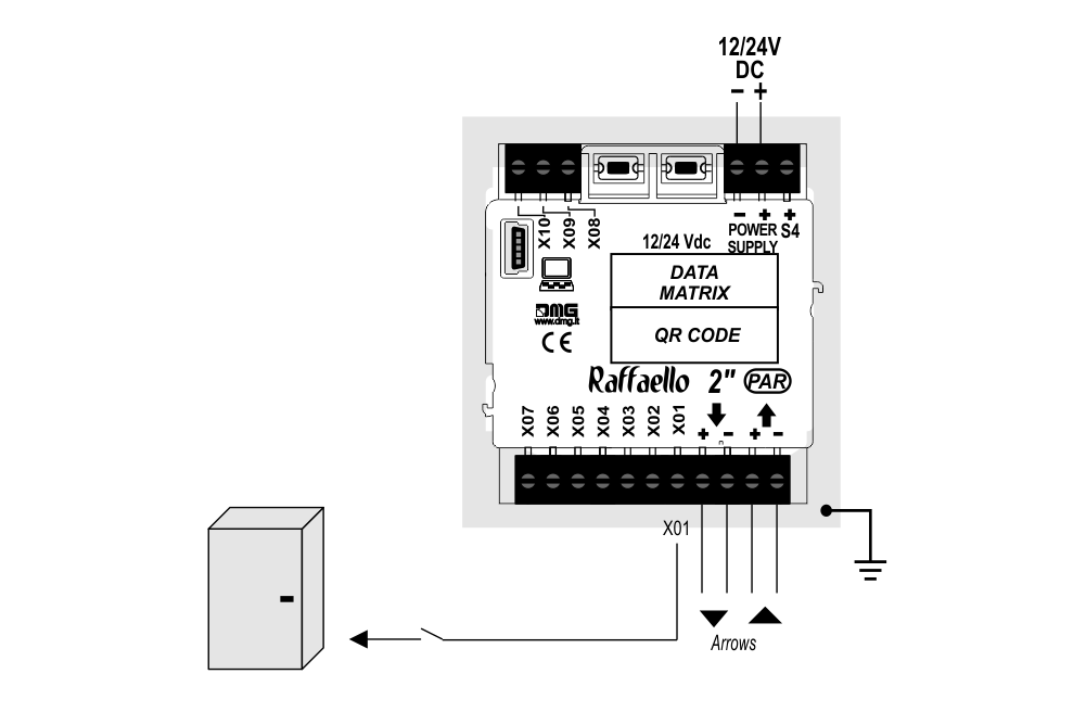
1 Wire / Floor
10 floors max.1 Wire / Segment
29 floors max. (-9, 0, 19)Gray / Binary
72 floors max. (-9, 0, 62)TKE/MEA/Autinor
SERVICE MESSAGE Wiring
Parallel display
CAN serial display (*)
(*) – Service messages can also be piloted, through serial bus, in two different ways:
- by controller DMG
- by encoder DEUM.M15
Settings
 Setup Key Setup Key |  Exit / Back Exit / Back |  Access Menu Key Access Menu Key |  Value setting (>3 sec.) Value setting (>3 sec.) |
General
| MENU | MENU ITEM | AVAILABLE CHOICES | INPUTS | |||
|---|---|---|---|---|---|---|
| Parallel | CANBUS | |||||
| Input | Serial / 1 wire per floor / segment Gray / Binary / Pos.Sensor TKE / MEA / Autinor / CAN DMG | • | • | |||
| Options | Interface Options | Arrow Configuration | Direction / Next Dir. | • | ||
| Car at Floor | No / Yes | • | ||||
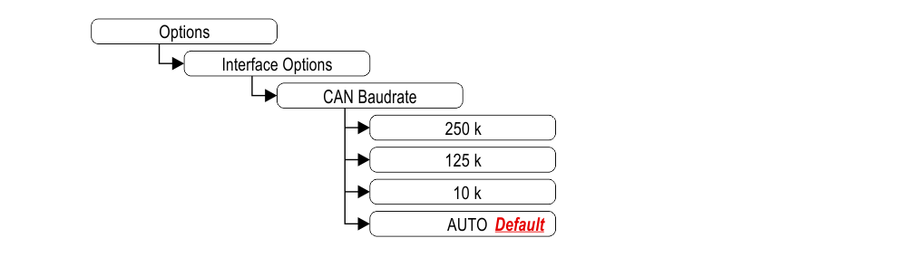
| CAN Baudrate | 250k, 125k, 10k, Auto | • | ||||
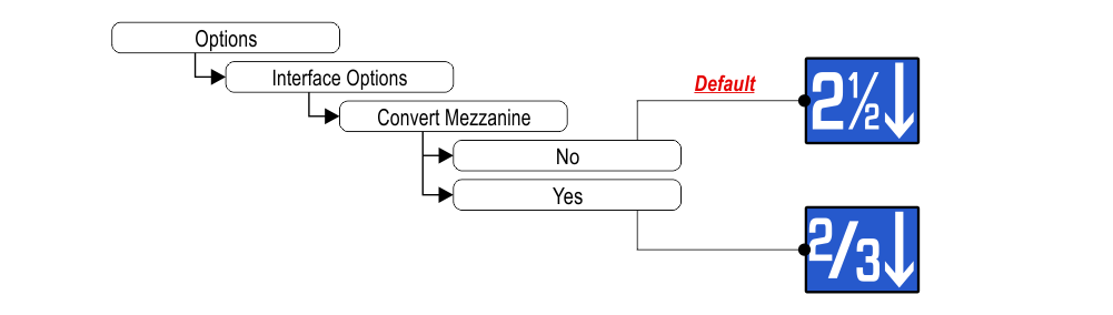
| Convert Mezzanine | No / Yes | • | ||||
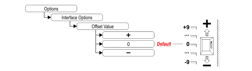
| Offset Value | -9 / ... / 0 / ... / +9 | • | ||||
| First Visualization | Blank / Zero | • | ||||
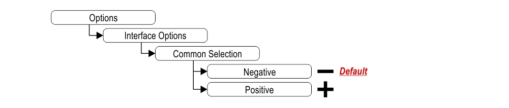
| Common Selection | Negative / Positive | • | ||||
| Arrow Type | Fixed arrows / Scrolling arrows | • | ||||
| Enable AUX Signals | 10 + 0 / 6 + 4 | • | ||||
| Input Filtering | 0 ... 20 | • | ||||
| Screensaver timer | Disabled / 10-20 / 30-60 / 60-120 | • | • | |||
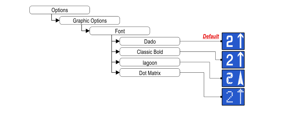
| Graphic Options | Font | Dado / Classic Bold / Lagoon / Dot Matrix | • | • | ||
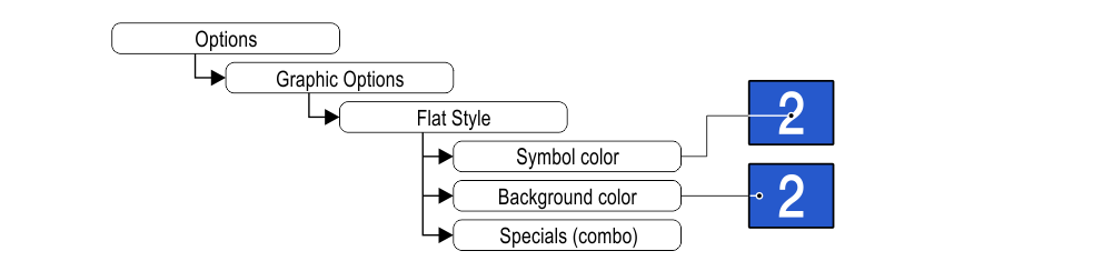
| Flat Style | Symbol color | White / Red / Orange / Blue / Gray / Black | • | • | ||
| Background color | Black / Pacific Blue / Navy Blue / Reef Blue / Light Gray /White / Orange / Red | • | • | |||
| Specials | White-Green / White-Lilac / Purple-Yellow / White-Gray | • | • | |||
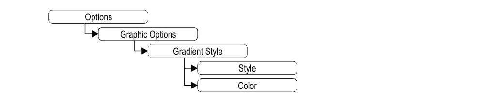
| Gradient Style | Style | Black & White / Red Passion / Gray Goose / Blue Shades | • | • | ||
| Color | Galaxy / Ocean Dream 2/1 / Reef Blue / Purple haze / ... | • | • | |||
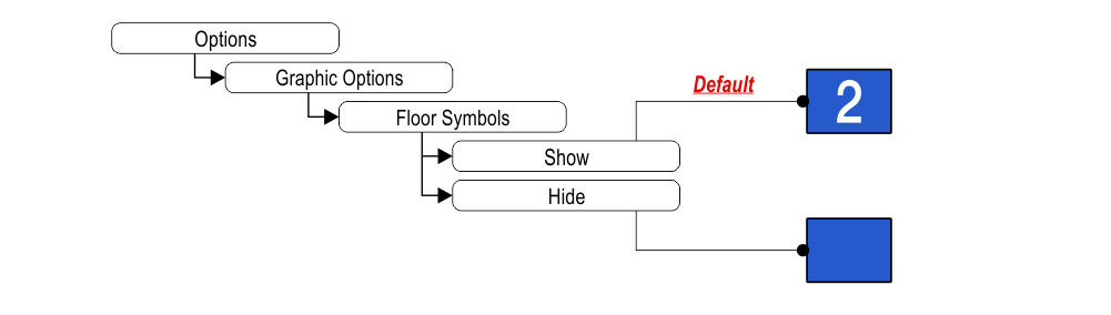
| Floor Symbols | Show / Hide | • | • | |||
| Arrows | Show / Hide | • | • | |||
| Fixed Symbols Positions | No / Yes | • | • | |||
| Filter Blinking Signals | No / Yes | • | • | |||
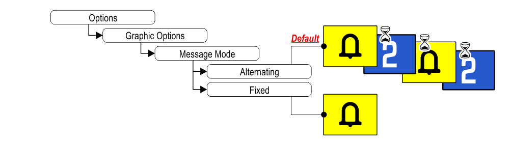
| Message Mode Orientation | Alternating / Fixed | • | • | |||
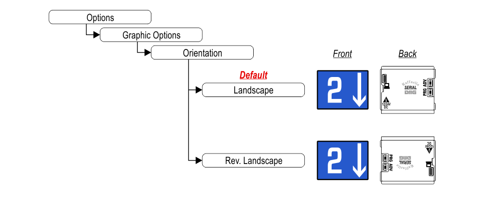
| Orientation | Landscape (Horiz.) / Portrait (Vert.) / Rev.Landscape / Rev.Portrait | • | • | |||
| Signal Inputs Configurations | Input S4 | • | • | |||
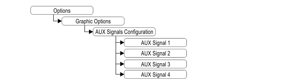
| AUX Signals Configurations | AUX Signal 1 / 2 / 3 / 4 | • | • | |||
| Reset All Settings | • | • | ||||
| ? | DEMO mode | No / Yes | • | • | ||
| Firmware Version / Life Time (internal use) | • | • | ||||
| Floor Numbers | Numbers / Letters | Choose the Numbers / Letters | • | |||
Arrow setting up
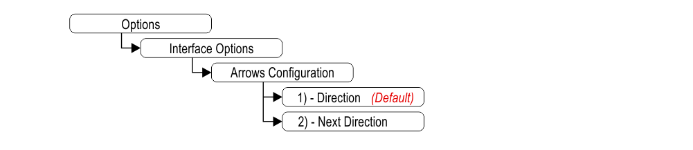 1) – Direction arrows (default)
2) – Next direction arrows (instructions below)
Next Direction Arrows enabled from input
Arrows light up only on the position indicators with the “NEXT DIRECTION” input powered.
 If the DEUM Encoder is used, please refer to the relevant manual
Next Direction Arrows locally programmed
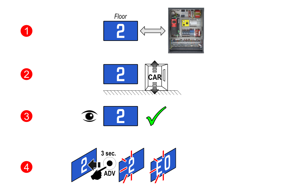
Through the addressing procedure one can permanently assign to each indicator the information of the floor on which it is mounted; in this way, next direction arrows only light up at the floor where the elevator car is positioned.
– Addressing procedure
1) – Connect all position indicators to the ENCODER or PLAYBOARD controller.
2) – Position elevator car on the floor of the Display which needs to be directed.
3) – Verify that the characters/numbers/letters visualized are the desired ones.
4) – Press and hold the ADV key and wait for the display to flash for 3 seconds to confirm.
5) – Repeat procedure for each floor.
 If the DEUM Encoder is used, please refer to the relevant manual
Set up CAN BUS protocol trasmission speed
Intermediate floors visualization
Set up floors OFFSET
Set up first visualization
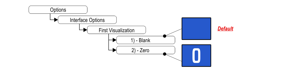
1) – It does not display any numbers
2) – Lowest floor
Set up Parallel position common input
Set up scrolling arrows
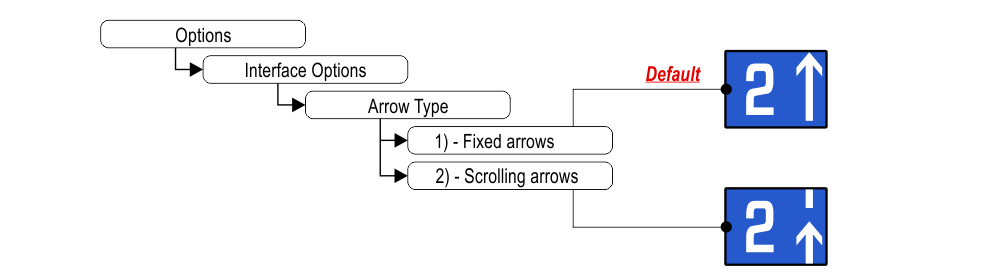
1) – Fixed arrows
2) – Scrolling arrows
Enable auxiliary signals
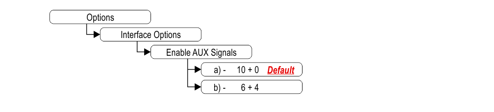
a) – 10 Floor parallel inputs (X01÷X10) + 0 AUX Signals
b) – 6 Floor parallel inputs (X01÷X06) + 4 AUX Signals (X07÷X10)
Set up the display delay of floor change
The display delay helps avoiding visualization errors during floor change.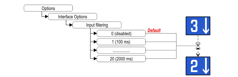
Associate the floor position indicator with the duplex controllers
The parameter allows to assign the display (floor) to a unique controller. The Duplex-Light typology includes 2 controllers with a single BDU line and a maximum of 2 displays at the main floor.
This parameter can only be set with the CAN protocol on the Pitagora 4.0 system.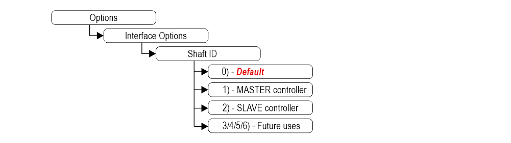 0) – To be associated with the lift car position indicator.
1) – The display will show the information of the MASTER controller.
2) – The display will show the information of the SLAVE controller.
3/4/5/6) – Future uses.
This parameter can only be set with the CAN protocol on the Pitagora 4.0 system.
0) – To be associated with the lift car position indicator.1) – The display will show the information of the MASTER controller.
2) – The display will show the information of the SLAVE controller.
3/4/5/6) – Future uses.
Enable energy saving function
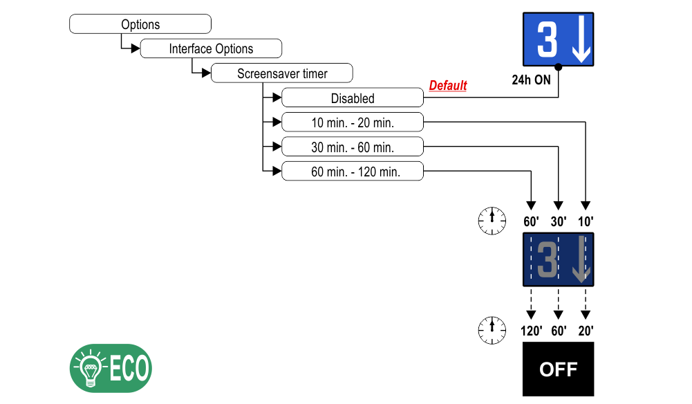
“Energy saving” mode to reduce consumption when idle.
Set up Font
Set up flat Style Color
Set up gradient Style Color
Show/Hide position
Show/Hide arrows

Set up Symbols position
Landscape orientation modes only.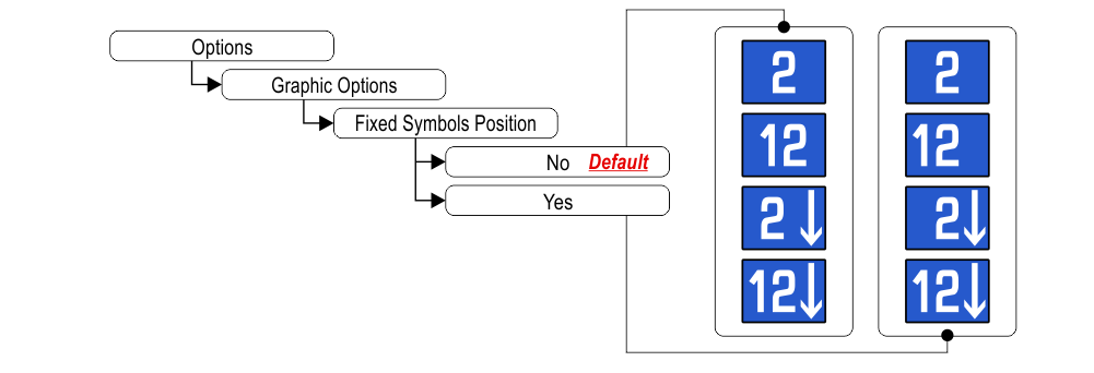
If “Yes”, the symbols will stay in fixed positions independently of the arrow status.
If “Yes”, the symbols will stay in fixed positions independently of the arrow status.
Signalizations (visualization)
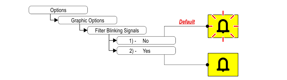
1) – Fixed or blinking signalizations (input from controller).
2) – Fixed signalizations.
Set up Viewing mode of signalization
Set up display orientation
Set up service message inputs

Set up auxiliary signal
Restore the factory settings

Floor customizations
1) Car at floor
2) Set up Floor Numbers / Letters
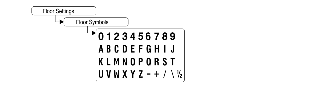
2) Set up Floor Numbers / Letters
Datasheet
Raffaello 2″
| Dimensions | 62×68 mm (STD) 62×76 mm (DZ1) 55×68 mm (D1) |
| Screen | 40,8×30,6 mm / 320×240 pixel |
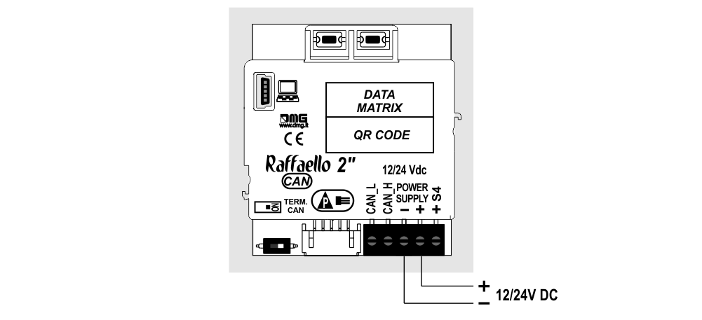
| Power supply (position input) | 12÷24V DC ±10% |
| Absorption | 12V DC: Max 49mA • 24V DC: Max 36mA |
| Indicators inputs | S4: 12÷24V DC ±10% |
| Operating temperature | -10°C ÷ +50°C |
Video Tutorial
The graphics parameters configuration
Offset value
The common programming
Firmware

Troubleshooting
| Fault description | Raffaello 2" | |
|---|---|---|
| Installation errors | The display does not light up | Check for the presence of 12/24VdC voltage. |
| Make sure that the type of voltage complies with that required (direct voltage, not alternating, not rectified). | ||
| Check the correct polarity on the power terminals. | ||
| Press the PRG key and make sure that the menu does not appear. In this case the screen is black but without input it could give the idea of being turned off. | ||
| The display does not show numbers and/or arrows | Make sure that the type and voltage value comply with those required for the inputs, make sure you have correctly set the type of common. | |
| Long presses of the PRG key are not detected by the display. | Update the display to the latest firmware version. | |
| Error messages | BLOCKED DEVICE INSERT CODE | If this message appears when you turn on the device, it means that it was not unlocked by mistake during production. Please contact DMG. |
| The display shows the indication "E" followed by a number X | In this case, it is a generic error indication due to an incorrect setting of the display. Please contact DMG | |
| Display defects | The display shows vertical lines | If the lines are fixed and black, please contact DMG. |
| The display shows horizontal lines | ||
| The display is white | Please contact DMG. | |
| The display has inverted colors or with a "negative" effect | Please contact DMG. | |
Download
| Reference | Version | Link |
|---|---|---|
| 1.1 | Download PDF (English) | |
| 2″ Mounting | 1.2 (current version) | Download PDF (English) |