(v 1.9)
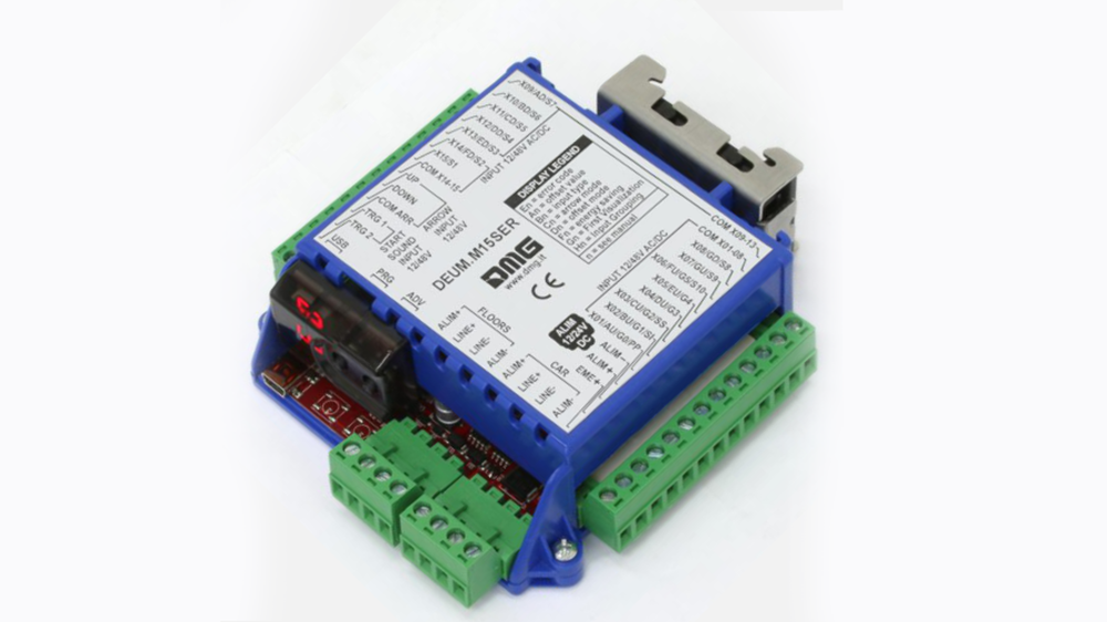
The DEUM.M15SER and DEUM.M15CAN encoders allow you to connect the DMG CAN or serial programmable displays and the CARUSO voice synthesizer to any type of controller.
The main specifications are as follows:
- Power supply: 12/24V dc;
- Up to 15 inputs;
- Possibility to automatically manage a floor detection kit independent from the control panel (controller). The encoder can thus provide details about the position of the elevator car, its direction and send floor messages.
Safety and usage cautions
Before installing our products, we recommend you to consult the section about safety and usage cautions at the link below.

Main features
- Input protocols: 1 wire per floor • 1 wire per segment • Binary/Gray 7 bit • Serial MEA / AUTINOR / TKE
- Independent position sensor
- Self diagnosis: internal LED + message on position indicator
- Signalization and emergency lamp controls are present in the elevator car display box
- Position and service scrolling message control for dot matrix display
- Differentiated control of the scroll arrows (yes / no) based on the movement of the elevator car.
- Encoder can be programmed in a serial way by DMG upon request on the order or directly on site through the two pushbutton ADV and PRG
- “Energy saving” mode to reduce power absorption when the system is idle
General Layout
– CAN serial output
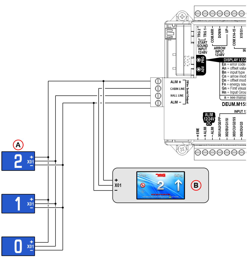
– 3 Wires serial output
 A) – Terminals for connecting display and voice synthesizer (CAN serial output)
B) – Terminals for connecting display and voice synthesizer (3 Wires serial output)
C) – Programming keys + Self-diagnosis LED
D) – 2 digit display
E) – Programming connector (USB Mini-B)
F) – Synthesizer trigger / gong
G) – Arrows
H) – Position inputs (9 – 15)
I) – Position inputs (1 – 8)
L) – Power supply 12/24V dc
– 3 Wires serial output
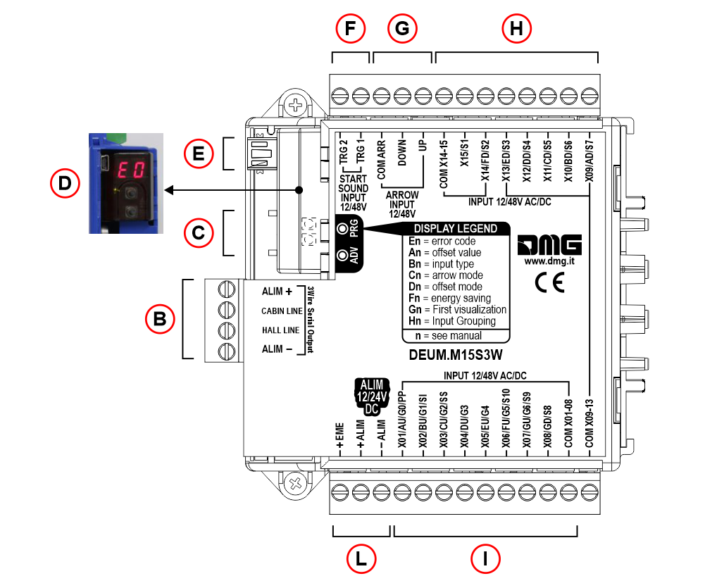 B) – Terminals for connecting display and voice synthesizer (3 Wires serial output)
C) – Programming keys + Self-diagnosis LED
D) – 2 digit display
E) – Programming connector (USB Mini-B)
F) – Synthesizer trigger / gong
G) – Arrows
H) – Position inputs (9 – 15)
I) – Position inputs (1 – 8)
L) – Power supply 12/24V dc
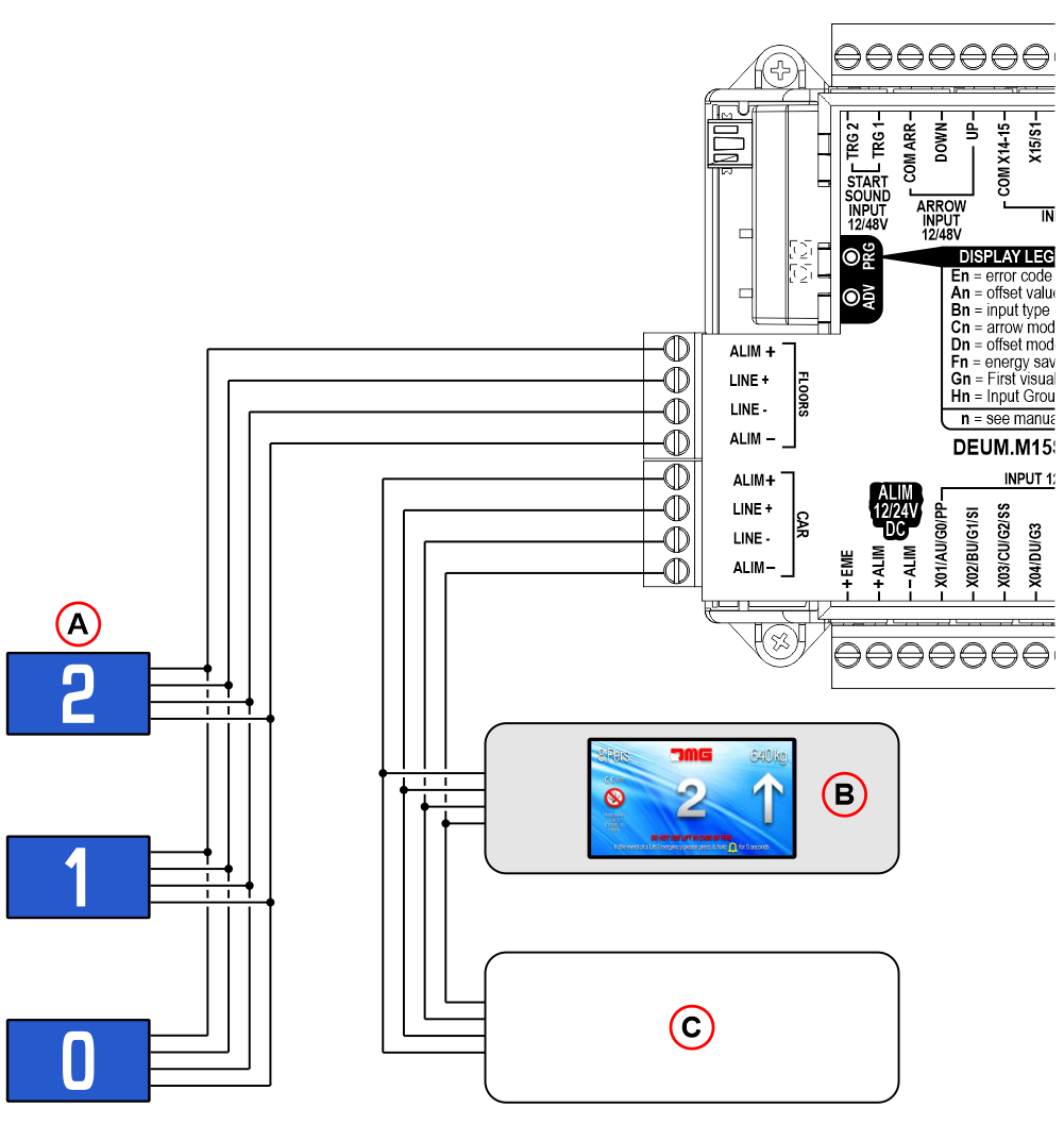
– RS485 serial output
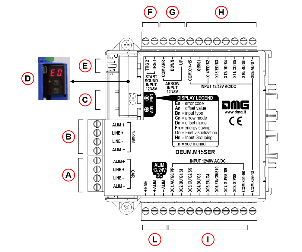 A) – Terminals for connecting display and voice synthesizer (cabin)
B) – Terminals for connecting display and voice synthesizer (floors)
C) – Programming keys + Self-diagnosis LED
D) – 2 digit display
E) – Programming connector (USB Mini-B)
F) – Synthesizer trigger / gong
G) – Arrows
H) – Position inputs (9 – 15)
I) – Position inputs (1 – 8)
L) – Power supply 12/24V dc
Wiring Instruction
Inputs
Position inputs
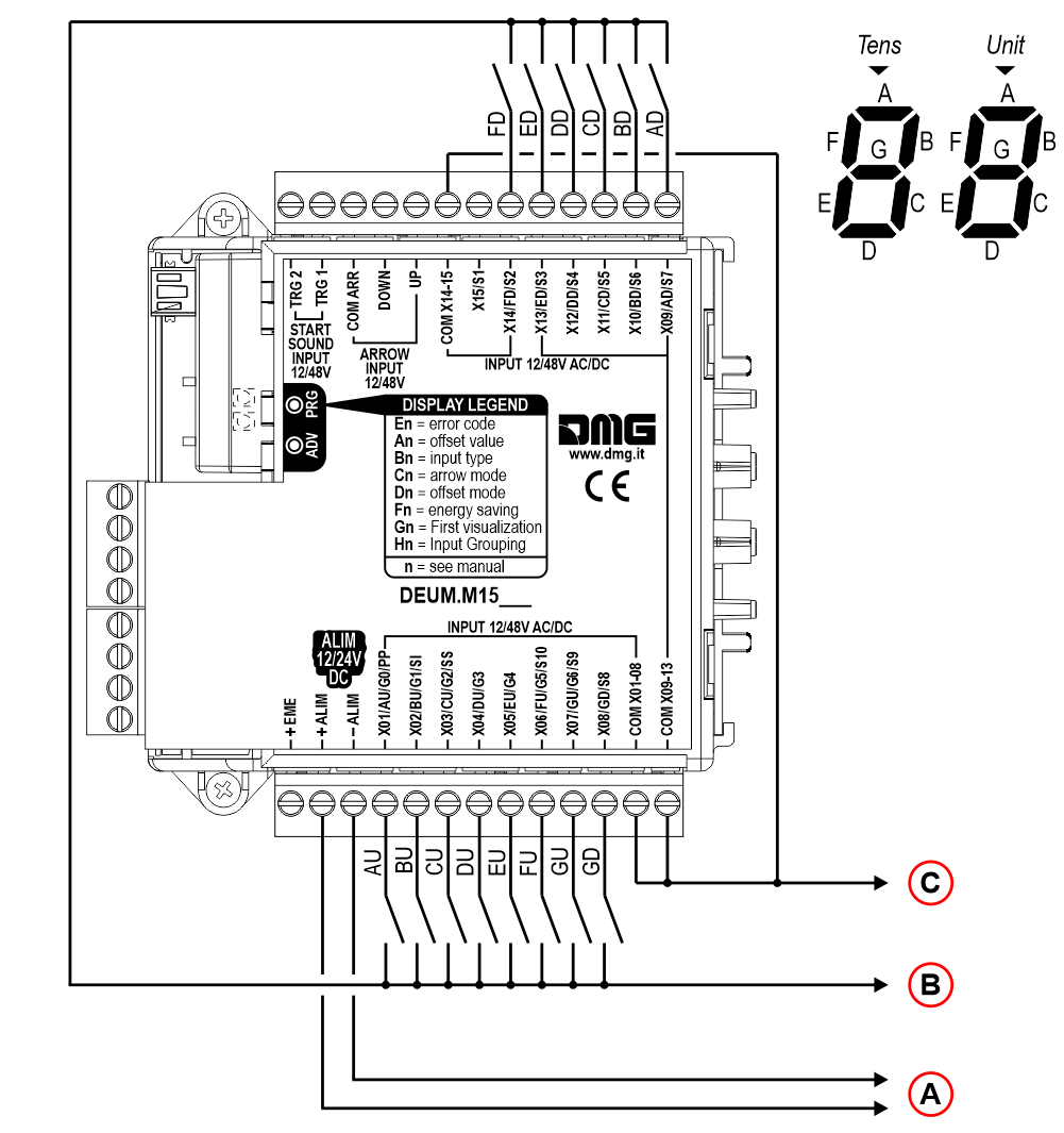
– 15 floors max
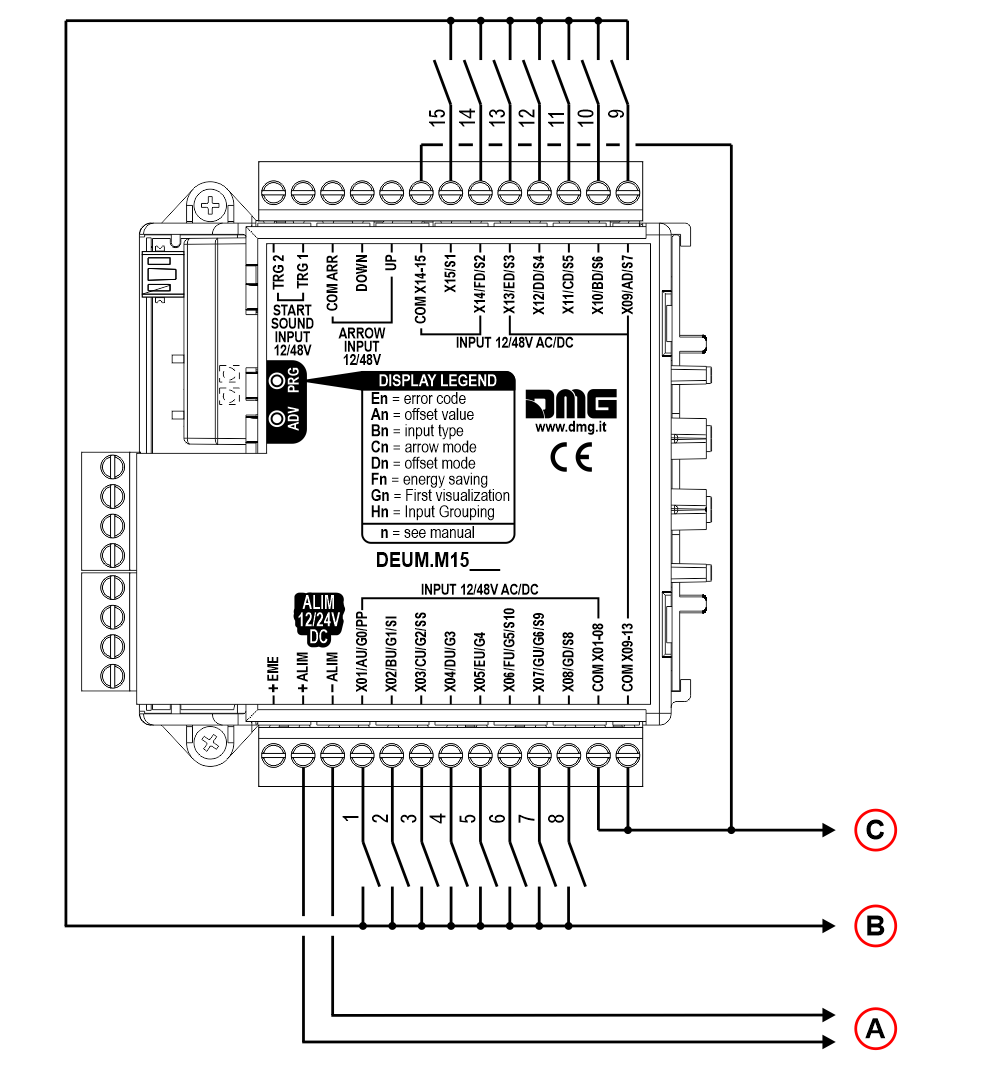 A) – Power supply 12/24V dc
B) – Power supply input 12/48V ac/dc (The input “X01” corresponds to the lowest floor.)
C) – Common input
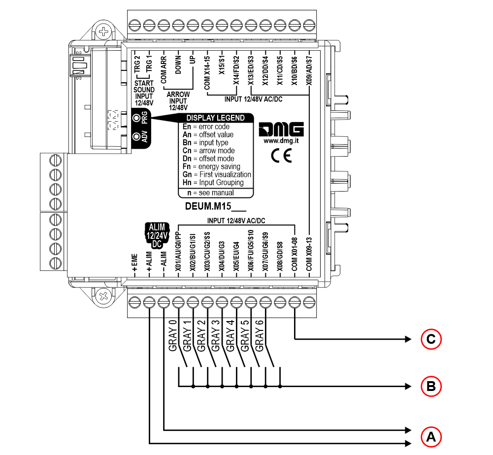
– 109 visualizations max (-9, 0, 99)
 A) – Power supply 12/24V dc
B) – Power supply input 12/48V ac/dc
C) – Common input
– 100 visualizations max (-9, 0, 90)
 A) – Power supply 12/24V dc
B) – Power supply input 12/48V ac/dc
C) – Common input
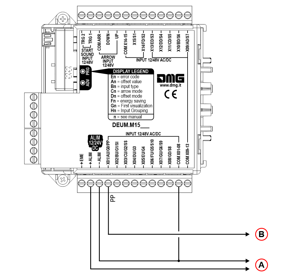 A) – Power supply 12/24V dc
B) – Control panel display output (controller)
If the control panel (controller) does not provide signals for position, direction and voice messages, an automatic floor detection kit can be connected to the encoder.
Installation:
1) – Connect the two magnetic NC sensors to the DEUM.
2) – Put two magnets on the corresponding guides for each floor (both impulsors are disengaged with cabin at the floor).
3) – Add a third magnet to main floor so that both sensors are engaged when cabin is at floor (system reset after power shortage or errors in counting floors).
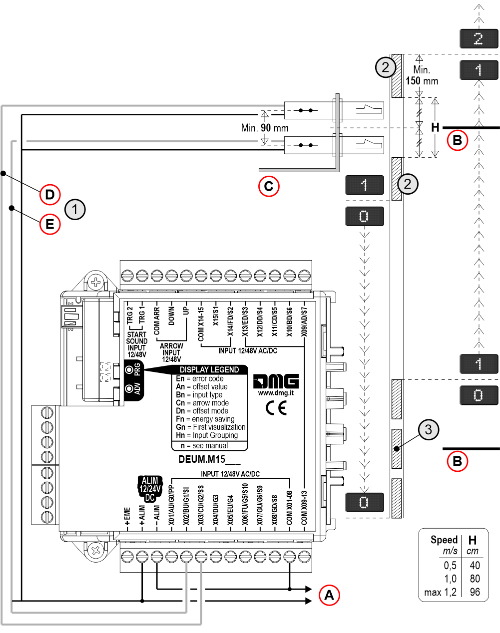
A) – Power supply 12/24V dc
B) – Floor / main floor
C) – Bracket fixed to the Top of elevator car
D) – Upper sensor
E) – Lower sensor
Note: Pre-wired sensor kit + magnet and bracket available on request.
Indicators and emergency lamp inputs
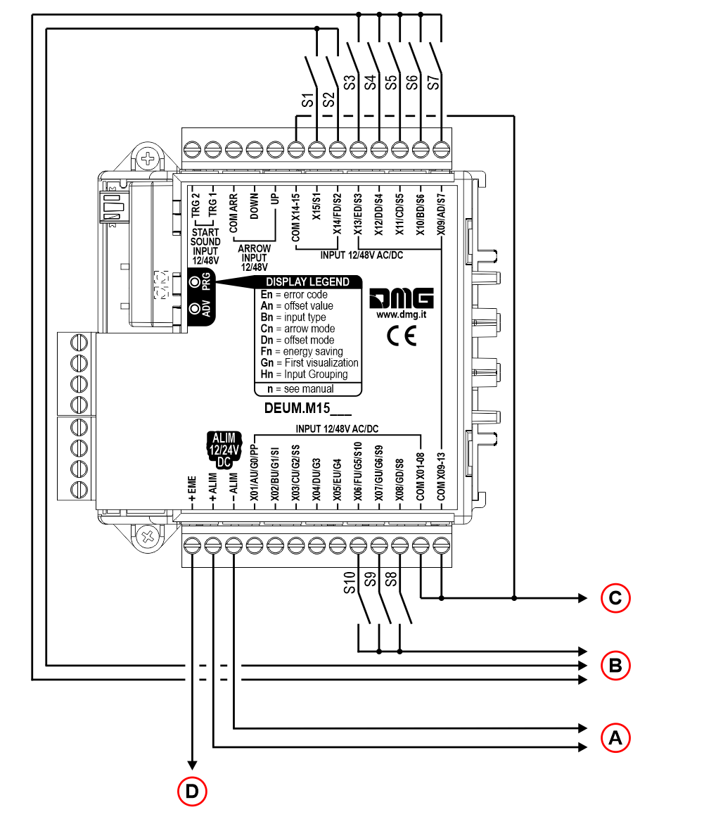
A) – Power supply 12/24V dc
B) – Power supply input 12/48V ac/dc
C) – Common input
D) – Upon powering the EME+ input (12/24V emergency supply) the emergency lamp is activated
| S1 | Alarm sent |
| S2 | Communication established |
| S3 | Overload |
| S4 | Firefighters |
| S5 | Car priority |
| S6 | Doors opening |
| S7 | Doors closing |
| S8 | Energy saving |
| S9 | Out of service |
| S10 | Inspection |
Direction arrow input
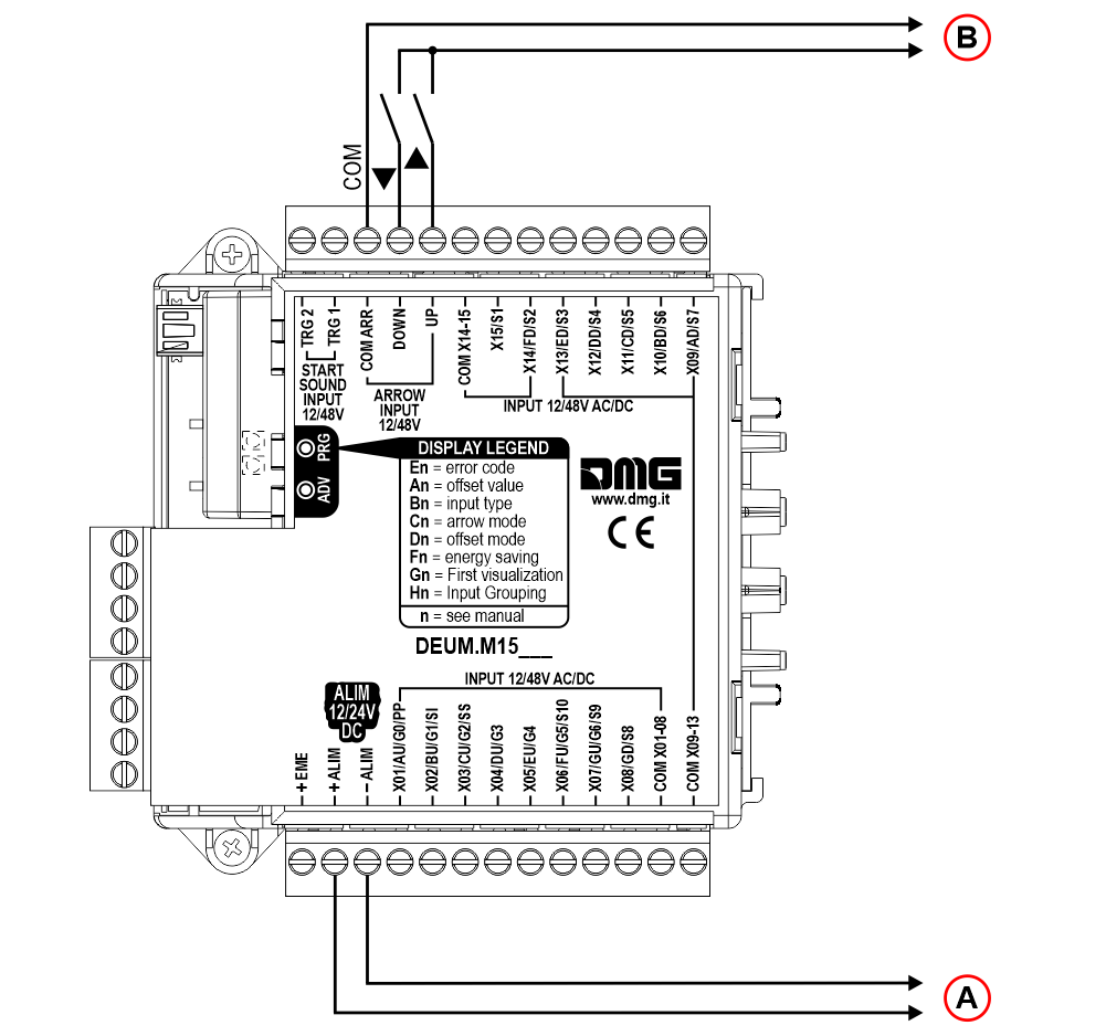
A) – Power supply 12/24V dc
B) – Upward/downward arrows 12/48V ac/dc
Note: “Automatic floor sensor” (“Programming > Custom settings > Encoding settings > B6“) for position sensors can be enabled without using the arrows terminals.
In case of position sensors it is possible to enable the option “automatic sensor of floor”, without using arrows input.
Trigger input (gong/voice synthesizer)
This input triggers the voice messages on DMG Caruso voice synthesizer and the gong.

A) – Power supply 12/24V dc
B) – Voice synthesizer/gong trigger (12/48V ac/dc)
Note: In the case of position sensors it is possible to enable the “automatic sensor of floor” option without using the trigger inputs (TRG1/2).
“Programming > Custom settings > Encoding setting > B6“
Serial Outputs
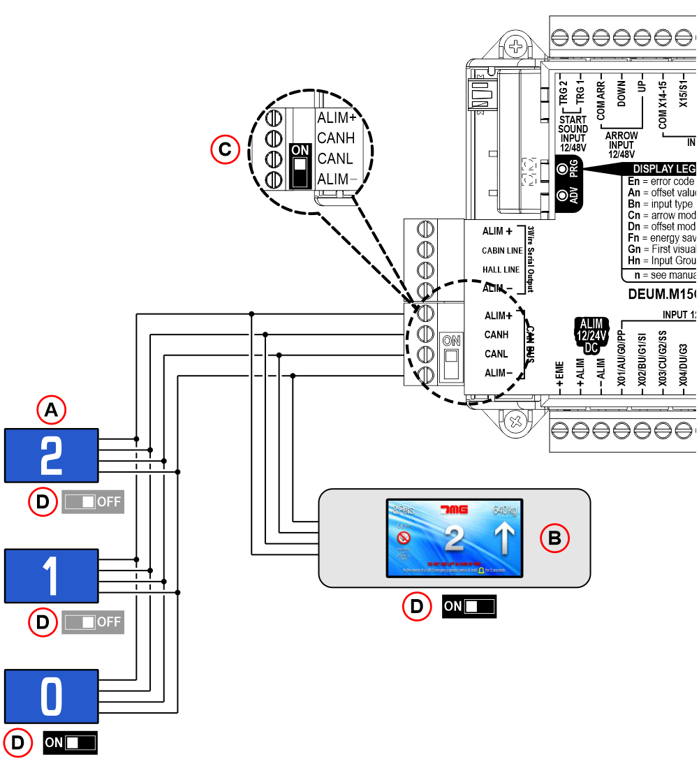 A) – CAN serial Position Indicator (Floor)
B) – CAN serial Position Indicator (Car)
C) – TERMINATION RESISTOR. If ONLY the elevator car position indicator or ONLY the floor ones are present, the CAN line termination must be activated on the DEUM.M15CAN as shown in the diagram.
D) – Switch TERM.CAN. Activate the termination of the CAN line on the elevator car display and on the last display at floor.
E) – Additional wiring with absorption > 2A (about 16 position indicator)
Dip-Switch status |
|||
|---|---|---|---|
| On the DEUM encoder | On the position indicator (Car) | On the position indicator (Floor - the last) |
|
| Only the cabin position indicator is present | - | ||
| Only the position indicators at floors are presents | - | ||
| All position indicators are presents (Car + Floors) | |||
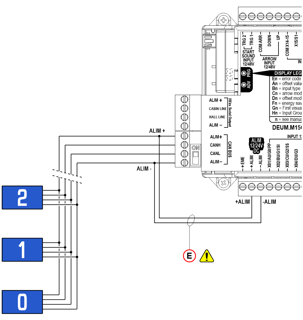
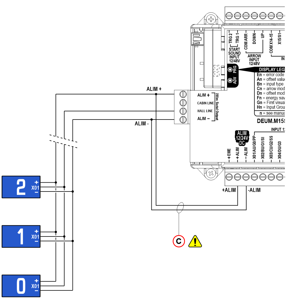
 A) – Position Indicator (Floor)
B) – Position Indicator (Car)
C) – Additional wiring with absorption > 2A (about 16 position indicator)
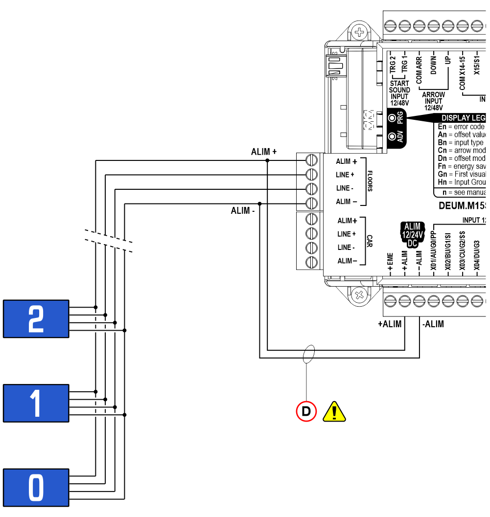
 A) – Position Indicator (Floor)
B) – Position Indicator (Car)
C) – “Caruso” voice synthesiser
D) – Additional wiring with absorption > 2A (about 16 position indicator)
Programming
 |  |  |  |
| Navigation menu key | Extended touch (> 3 seconds) Access menu key Value setting | Set-up key | Firmware version |
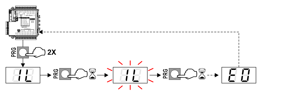
Visualization settings
To set up specific letters/numbers, bring the lift to the floor and follow the diagram.

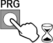
Default set-up
All DEUM factory parameters can be reset using the following RESET procedure:
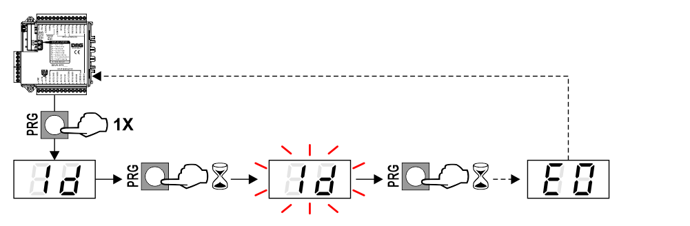
Restore last configuration
Restore the last configuration loaded with the DEUM Coder software tool.
Custom settings
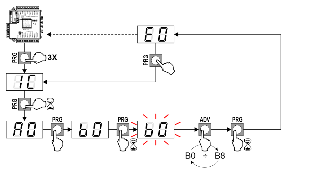
B0 = 1 Wire / floor (Default)
B1 = Gray code
B2 = Mea
B3 = Autinor
B4 = Manual sensor (with arrows and trigger input)
B5 = 1 Wire / segment
B6 = Automatic sensor (with automatic arrows and automatic trigger)
B7 = Binary code
B8 = TKE
C0 = Fix arrows (Default)
C1 = Scrolling arrow
C2 = Trigger dependent: Trigger ON = Fix arrows / Trigger OFF = Scrolling arrows (see also “Encoding setting” and “Direction arrow input”)
To use gong and next direction arrows you have to set C2 and set the position indicator for the “next direction”.
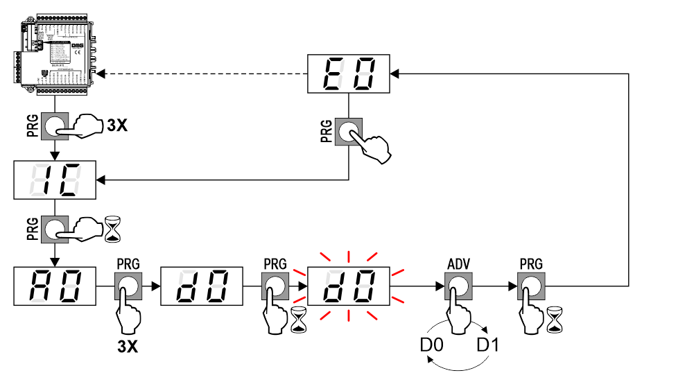
D0 = Negative offset (Default)
D1 = Positive offset
See also “Offset value setting”.
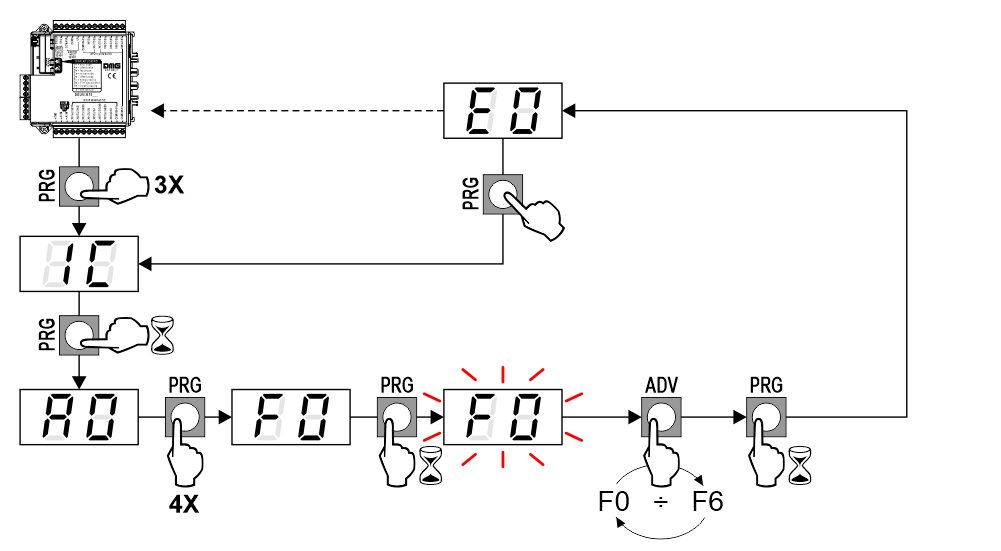
F0 (Default) = Disabled function: Supply the “S8” input (see “Indicators and emergency lamp inputs”) to command the function from other unit.
F1* = 10 minutes
F2* = 20 minutes
F3* = 30 minutes
F4* = 40 minutes
F5* = 50 minutes
F6* = 60 minutes
(*) = The “S8” input (see “Indicators and emergency lamp inputs“) must NOT be connected to the power supply.
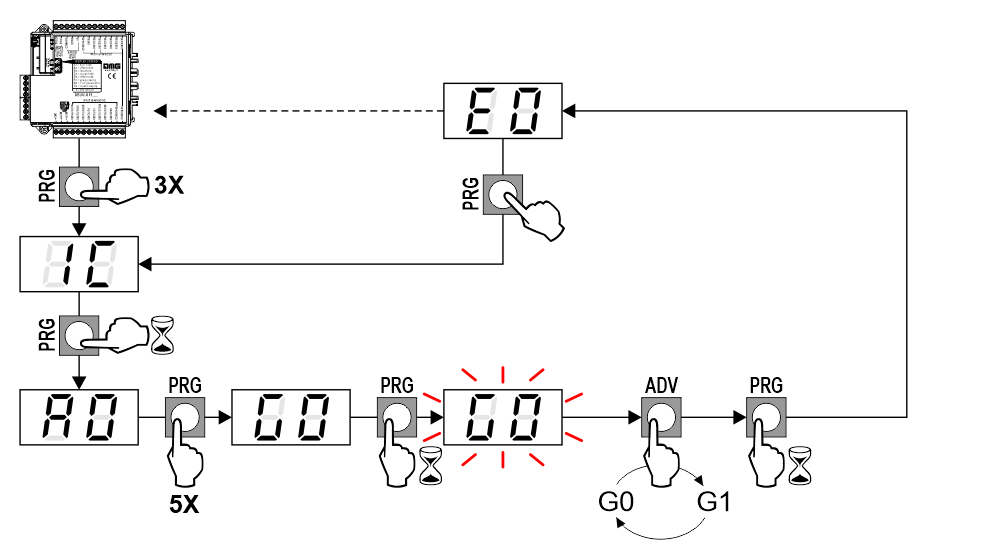
G0 = Blank (Default)
G1 = Lowest of the floors
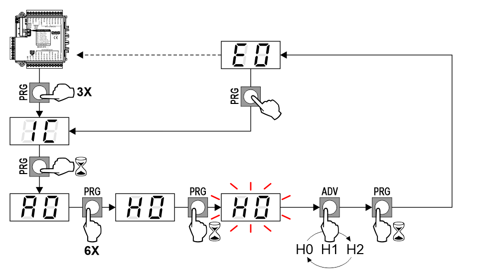
H0 = Position inputs: X01 ÷ X15 / Signals: 0
H1 (default) = Position inputs: X01 ÷ X08 / Signals: S1 ÷ S7
H2 = Position inputs: X01 ÷ X05 / Signals: S1 ÷ S10
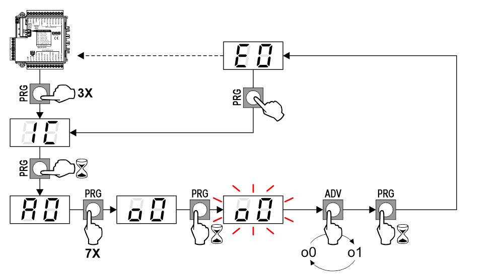
o0 (Default) = DEUM encoder transmits every active signalization.
o1 = DEUM encoder transmits only the higher priority active signalization. The priority of the signalization depends by the terminal: S1 = higher priority, S10 = lower priority
– Signals

S0 = OFF (Default)
S1 = ON (2500 ms)
– Change of Floor
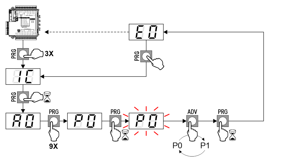
P0 = OFF (Default)
P1 = ON (100 ms)
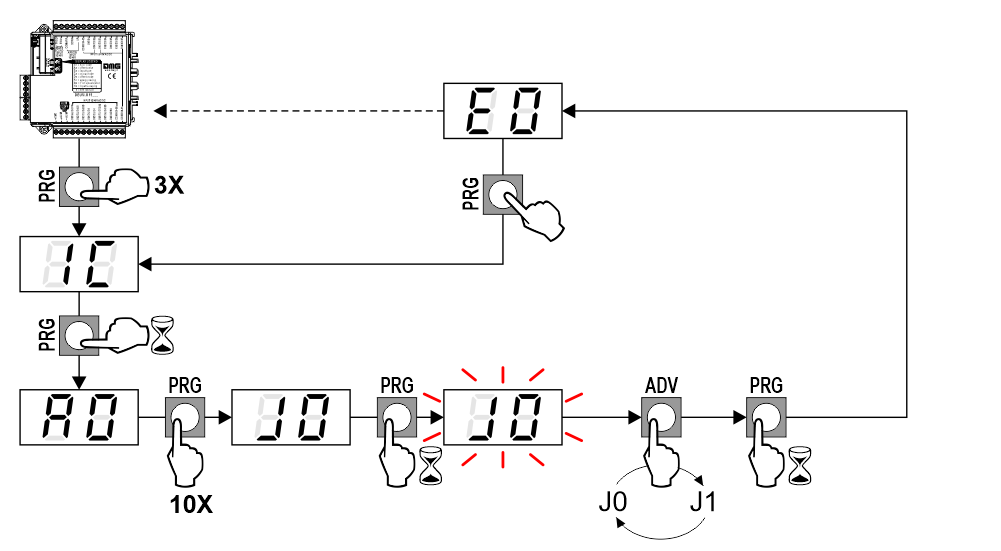
J0 = 10 kbps
J1 = 2 kbps
Self-diagnosis LED & Error list
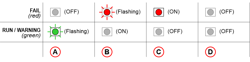 FAIL LED lits up for 1 second when the encoder is switched on.
A) – Regular operation
B) – Fault detected (see the “Error list” below)
C) – Encoder not working or not programmed
D) – Encoder not working or no power supply
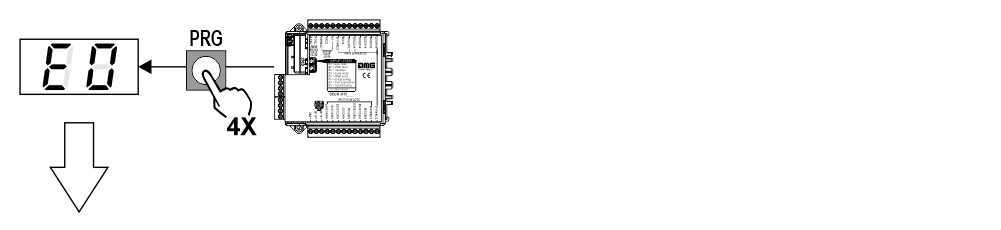
E0 = No error.
E1 = Unknown input protocol error (e.g. Gray or 7 unrecognised segments).
E2 = Data check result is wrong: enter default settings again.
E3 = Invalid MEA/AUTINOR input error (unrecognised signalization characteristics)
E4 = MEA/AUTINOR error, code not received (3 seconds have passed without recognizing any signal).
E5 = Error in reading sensor
E6 = Position sensor waiting for reset (position not settled).
E7 = The current floor cannot be associated with a visualization.
E9 = Unidentified generic error
LE = The “EME +” input is active on the encoder.
The code deletion happens automatically when the error is cleared.
Video Tutorial
| English | Italian |
Download
| Reference | Version | Link |
|---|---|---|
| 1.8 | Download PDF (English) | |
| CAN BUS protocol transmission speed | 1.9 (current version) | Download PDF (English) |