
The Pitagora 4.0 system provides serial wiring to connect the cabin push-button panels to the controller.
This solution is achieved through the use of 2 components, joined together by an 8-pole telephone cable:
- The TOC box positioned on the top of cabin (TOC) – It connects directly with the controller.
- The DMCPIT interface board positioned on the back of the cabin push-button panel – It allows you to manage all the signals that can be found inside a cabin push-button panel (buttons, displays, keys, etc.) with the exception of the telephone and intercom system.
Connecting the TOC box to the DMCPIT interface
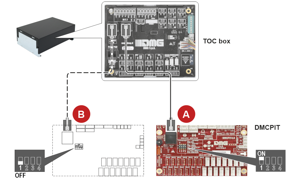
A) Cabin push-button panel A
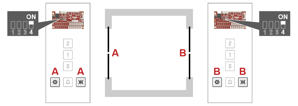
B) Cabin push-button panel B (double access). In this case it is important to identify the two DMCPIT interface boards via the on-board DIP-SWITCH.
Connecting the DMCPIT interface to the cabin components
Connecting the DMCPIT interface to the Position indicator
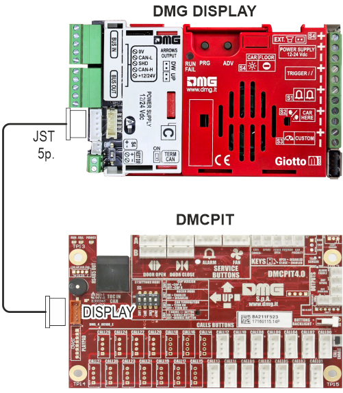
I display DMG sono collegati alla DMCPIT tramite cavo JST 5 poli.
Per approfondimenti sui singoli display fare riferimento ai link sotto:
Display MATISSE
Display GIOTTO
Display RAFFAELLO
Connecting the DMCPIT interface to the call and service Push-buttons
The DMCPIT interface board can manage systems with up to 14 calls (C40.COP14) or up to 28 calls (C40.COP28).
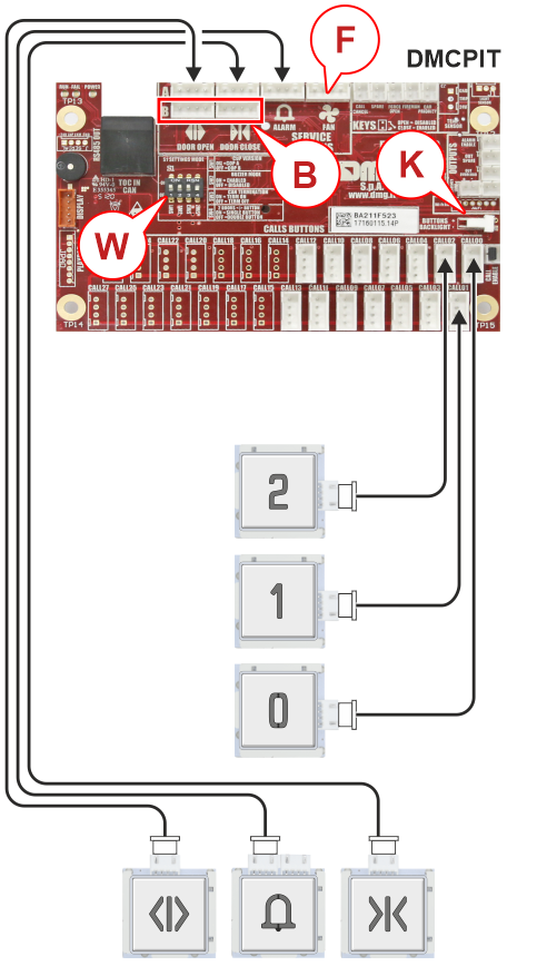
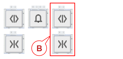
In case of double selective access managed by a single cabin button panel, the service buttons of the second access must be connected to the relevant inputs (B) on the same DMCPIT interface.
B) JST 4p. connectors for second selective access.
F) Fan – Bistable contact connected to the specific service button to manage cabin ventilation.
K) Used for 2-contact TWIN-light button backlight – Remove the jumper to connect the push-button. Re-insert the jumper if this feature is not used.
W) Dip-switch 4 relating to the assignment of the service buttons.
See below to set Dip-switch 4.
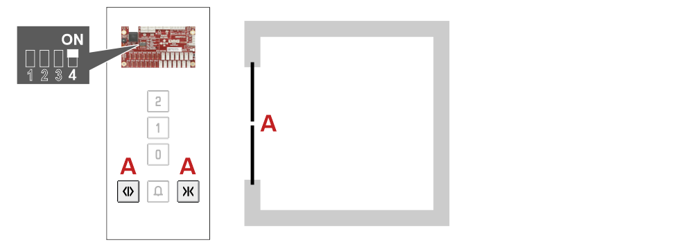
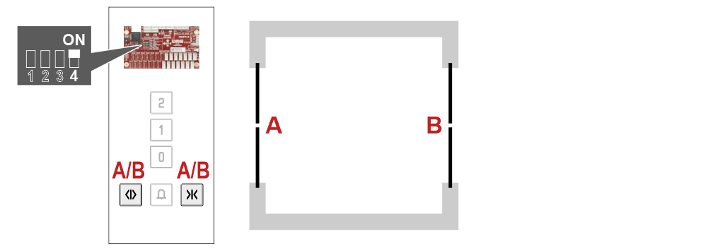
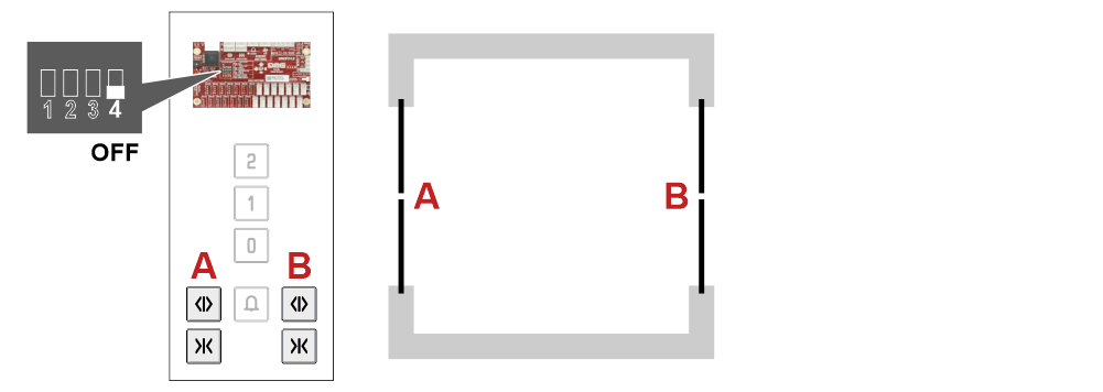
Setting dip-switch 4
– Single access –
– Double pass-through access • 1 push-button panel –
– Double selective access • 1 push-button panel –
– Double selective access • 2 push-button panels –
Connecting the DMCPIT interface to the Key contacts
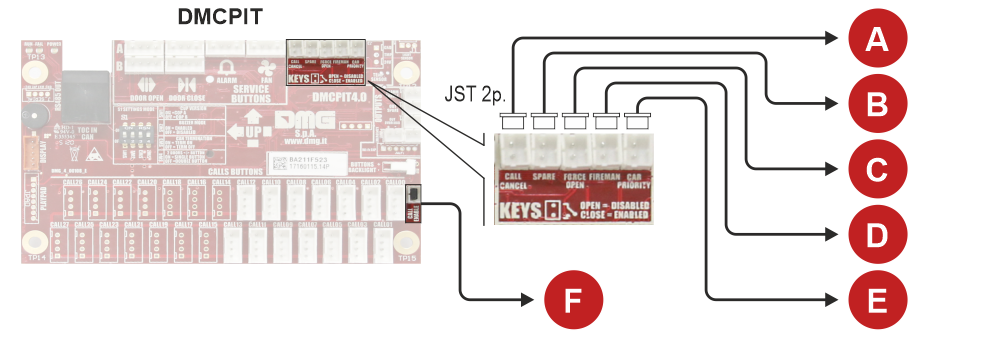
A) Call cancel
B) Spare (free / not assigned)
C) Force open
D) Fireman
E) Car priority
F) Call enable – Remove the jumper and connect the key contact to manage the call enablement. Re-insert the jumper if this feature is not used.
Connecting the DMCPIT interface to the Signals
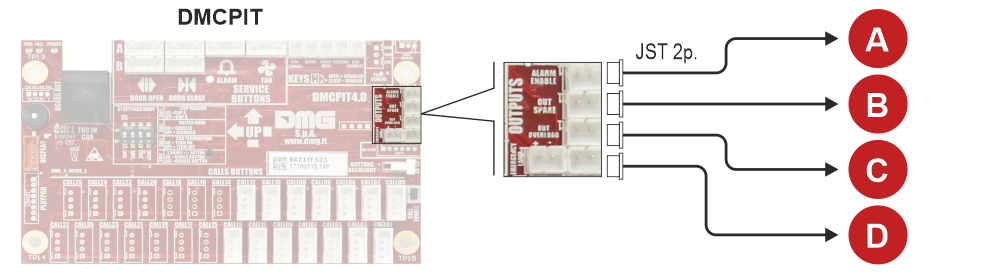
A) Battery low
B) Spare (free / not assigned)
C) Overload
D) Emergency lamp (it is possible to manage up to 2 emergency lamps) – Connecting the DMG emergency lamp according to EN81-20
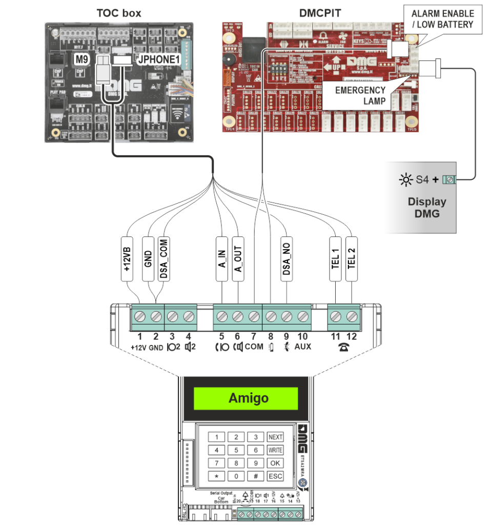
Connecting the emergency telephone
DMG AMIGO emergency telephone
Third-party emergency telephone
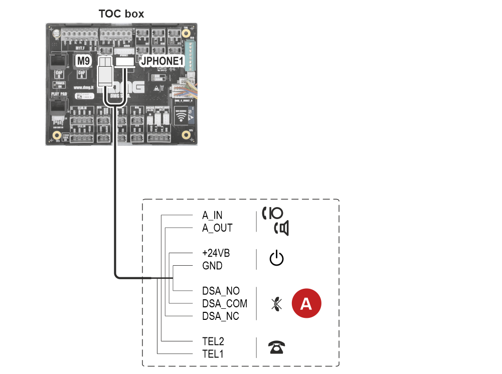
A) Unintentional activation filter (DSA) – It is a dry contact of a relay on the TOC board, which can be either normally open or normally closed.