(V 1.8)

Safety and usage cautions
Before installing our products, we recommend you to consult the section about safety and usage cautions at the link below.

Mounting
Frontal mounting
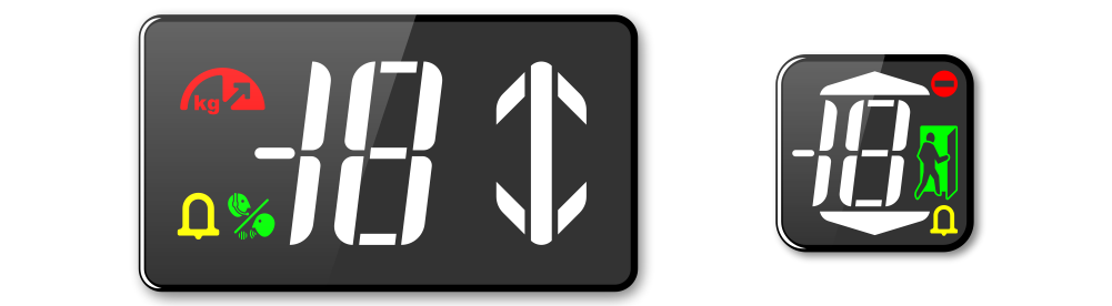
DB1 position indicator (with D1 Screen)
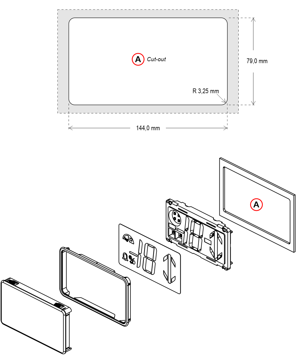
Frontal mounted on 0,7/3 mm pushbutton panel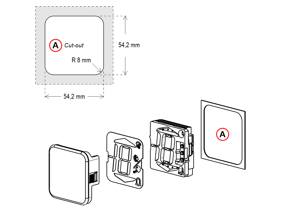 A) – Cut-out – Compatible with DMG D1 series displays
A) – Cut-out – Compatible with DMG D1 series displaysDB2 position indicator
Frontal mounted on 0,7/3 mm pushbutton panel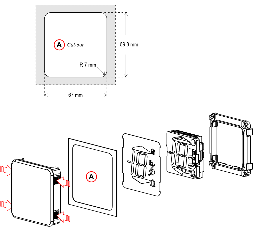
For easier mounting of the screen, press on the side flaps as indicated by the arrows in the image.
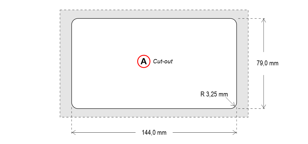
A) – Cut-out
For easier mounting of the screen, press on the side flaps as indicated by the arrows in the image.
A) – Cut-out
DB3 position indicator
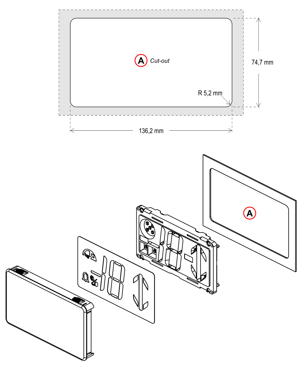
A) – Cut-out
DB4 position indicator
A) – Cut-out
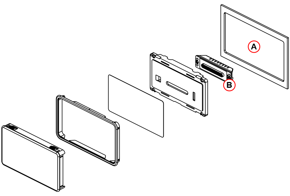
CTDB3 – Capacity plate

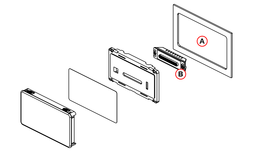
A) – Cut-out
B) – Optional Emergency lamp EN81-20 (see the relevant page for further information)
C) – Gong (optional)
CTDB4 – Capacity plate
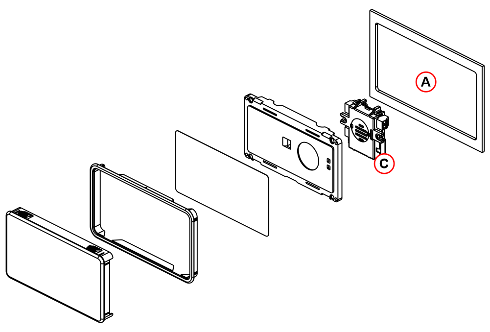
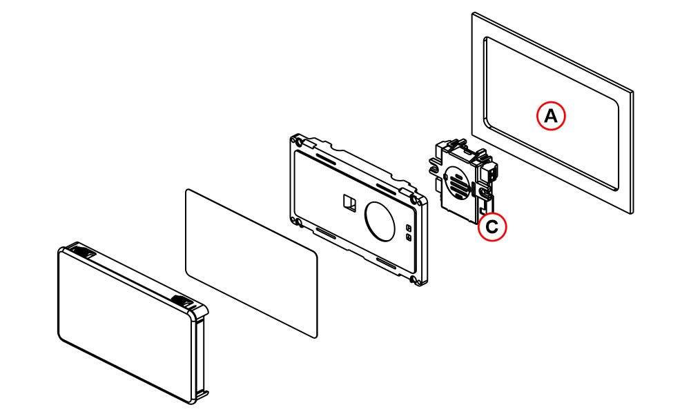
A) – Cut-out
B) – Optional Emergency lamp EN81-20 (see the relevant page for further information)
C) – Gong (optional)
Back mounting
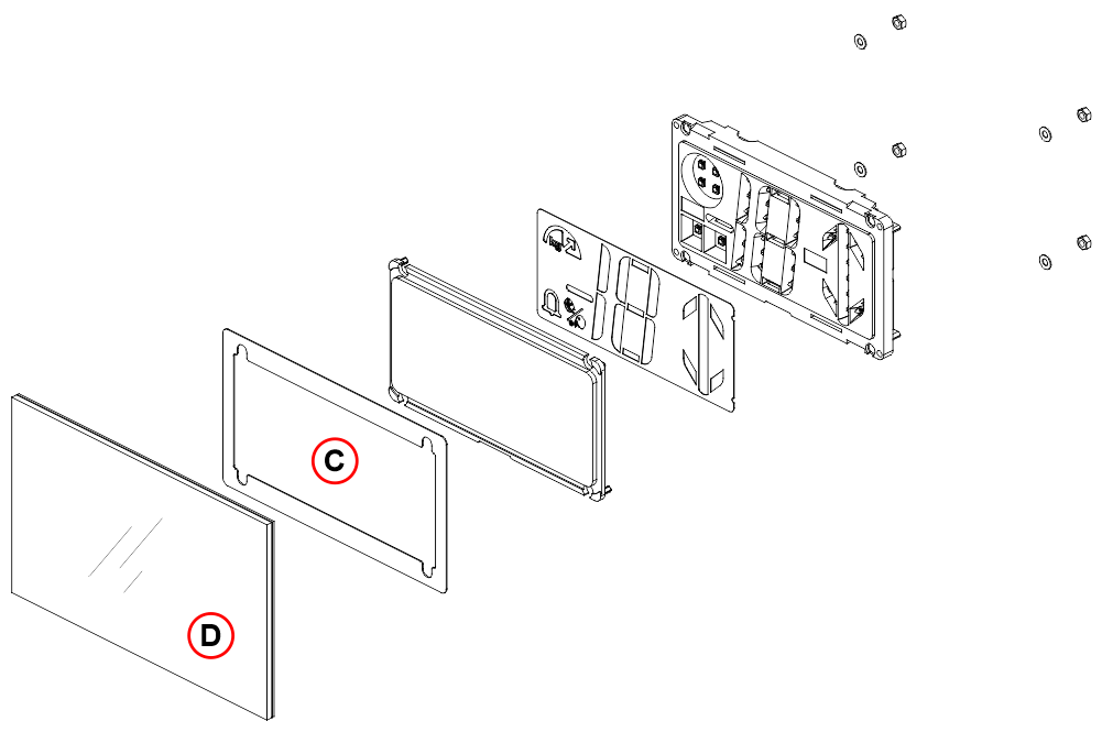
DB1 position indicator (for 1mm / 1,5 mm thickness plate only)
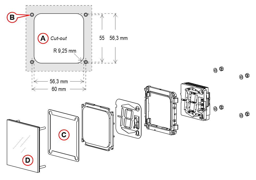
A) – Cut-out
B) – M3x16 welded pins
C) – Spacer (for 1mm thicknes plate only)
D) – Faceplate + screen
DB3 position indicator (for 1mm / 1,5 mm thickness plate only)
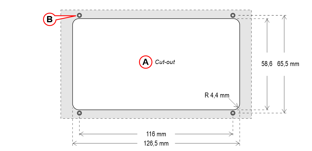
A) – Cut-out
B) – M3x12 welded pins
C) – Spacer (for 1mm thicknes plate only)
D) – Faceplate + screen
Wiring Instructions
Wiring of position and direction inputs
Pitagora 4.0
DMG
3-wires serial
DB1/DB2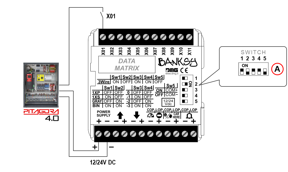 DB3/DB4
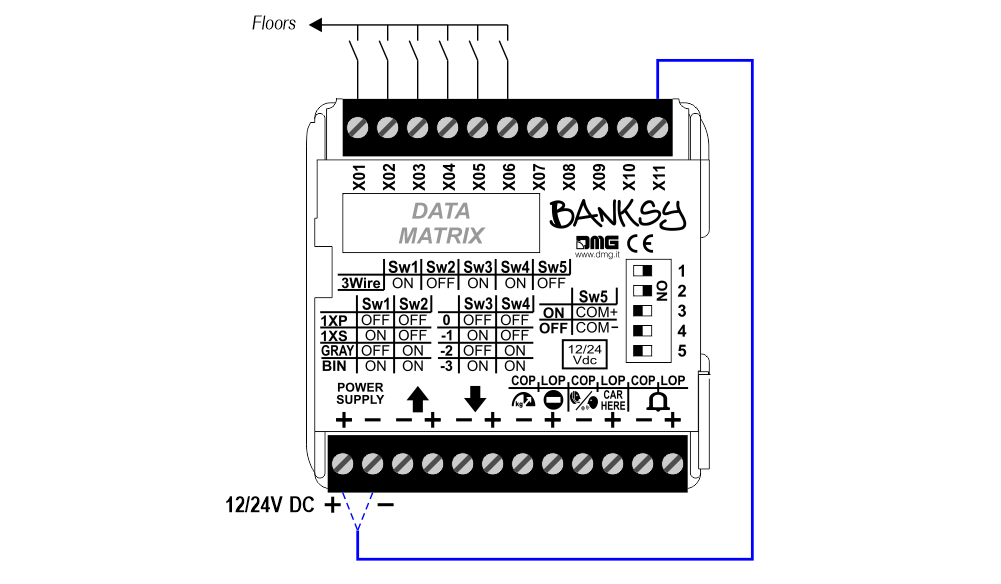
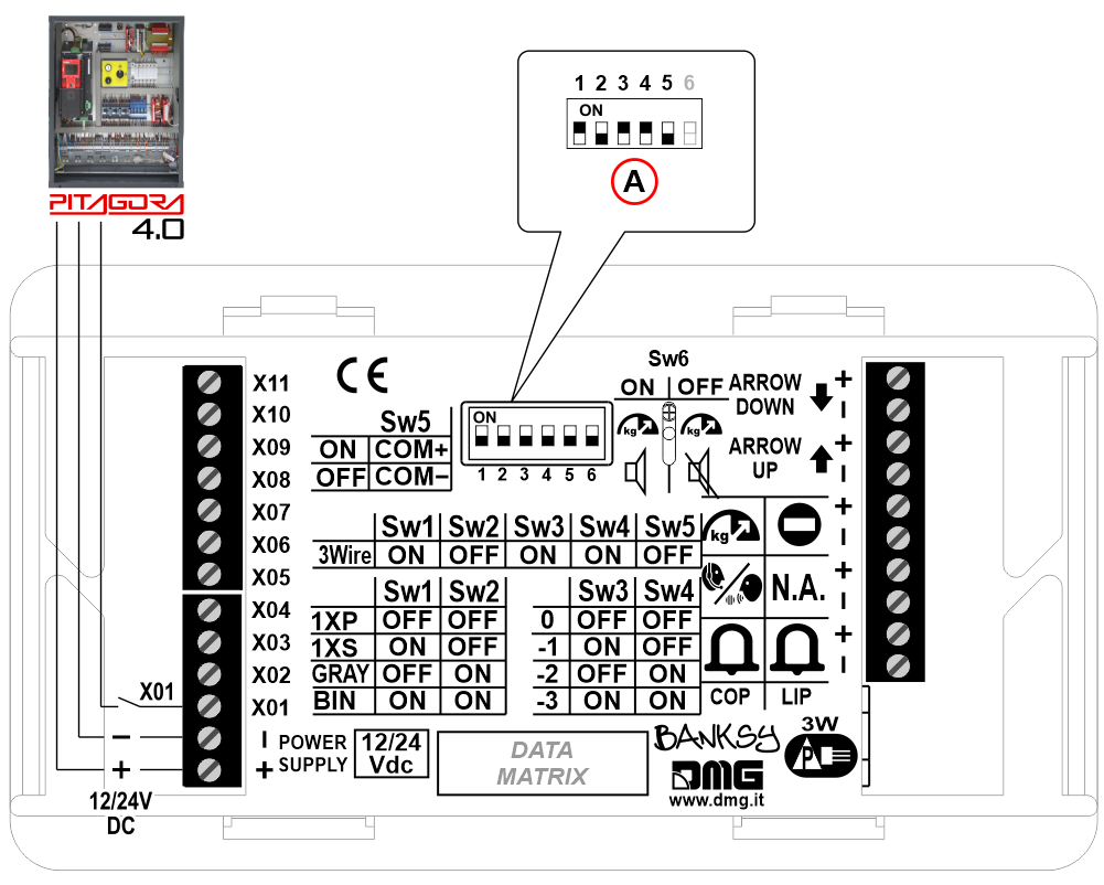 A) – Coding
3-wires serial (pre-wiring with JST)
DB3/DB4
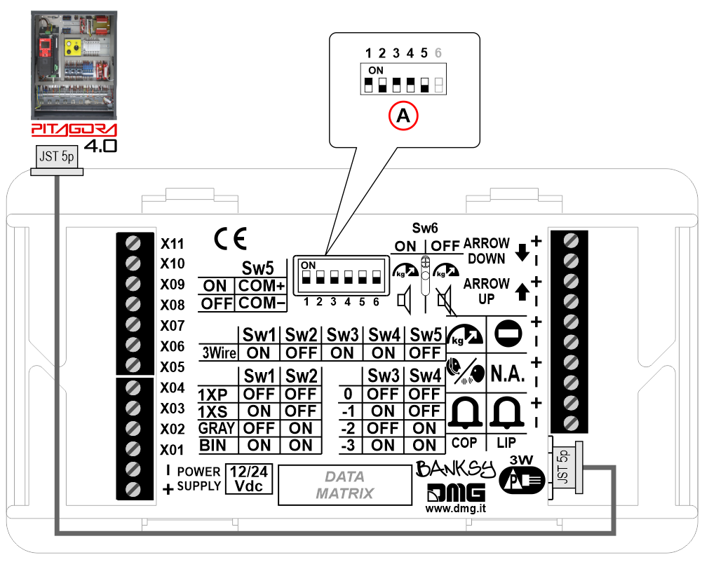 A) – Coding
 29 floors max. (-9, 0, 19)
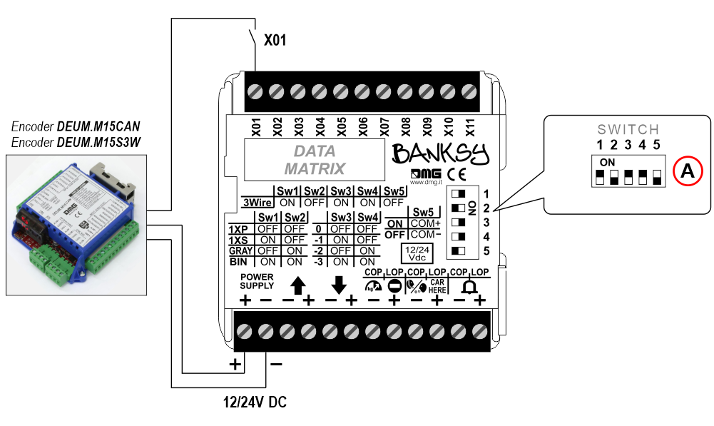
3-wires serial
DB1/DB2
DB3/DB4A) – Coding3-wires serial (pre-wiring with JST)
DB3/DB4
A) – Coding29 floors max. (-9, 0, 19)Encoder DEUM
 For more details please refer to the Encoder DEUM support page.
DMG
3-wires serial
DB1/DB2
 DB3/DB4
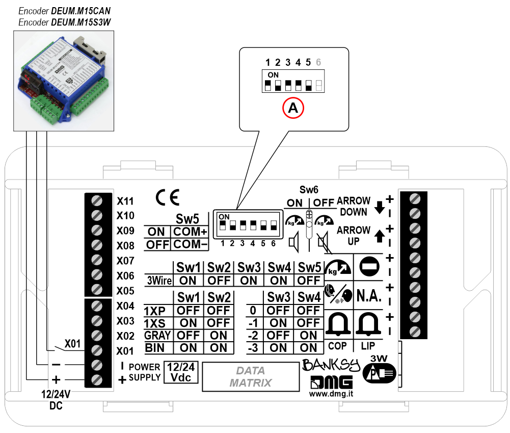
A) – Coding
29 floors max. (-9, 0, 19)Other Controllers
1 Wire / Floor
DB1/DB2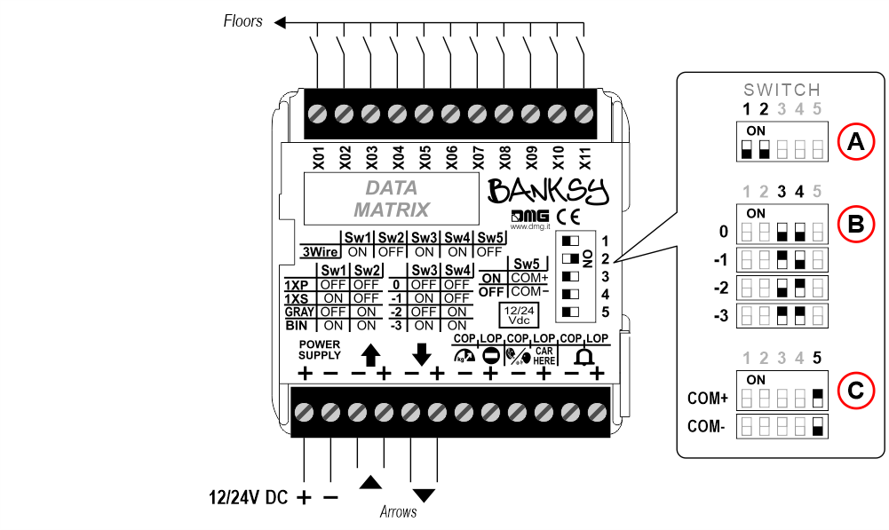 DB3/DB4
A) – Coding
B) – Offset (-3 ÷ 0)
C) – Common (Inputs)
11 floors max.
1 Wire / Segment
DB1/DB2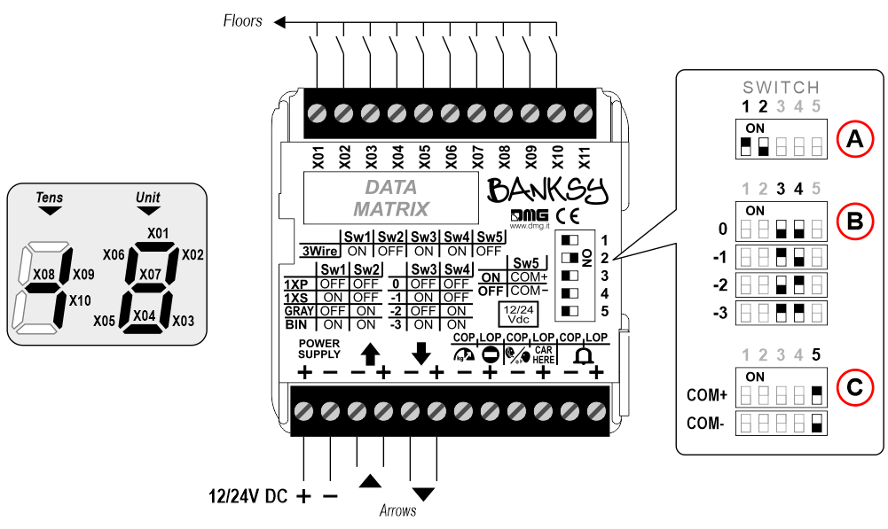 DB3/DB4
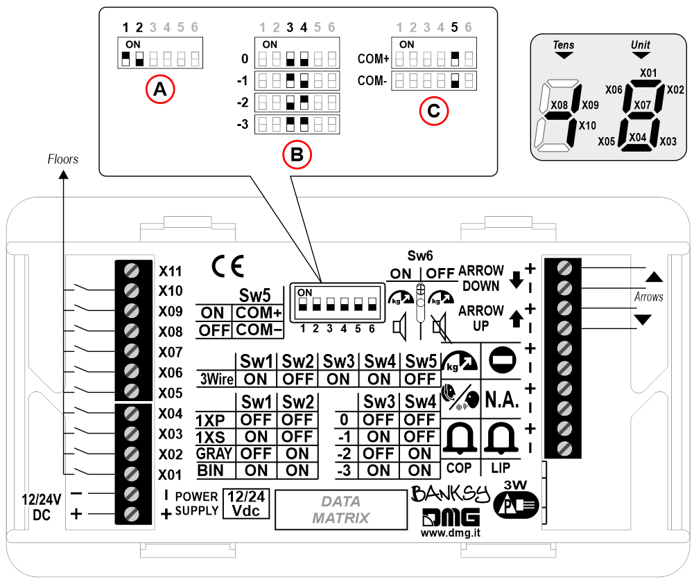
A) – Coding
B) – Offset (don’t use the dip-switch to set the offset)
C) – Common (Inputs)
29 floors max. (-9, 0, 19)
LETTERS DISPLAYED
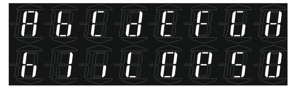
Gray
DB1/DB2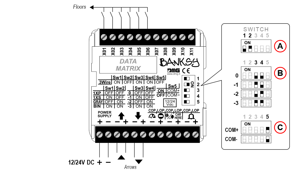 DB3/DB4
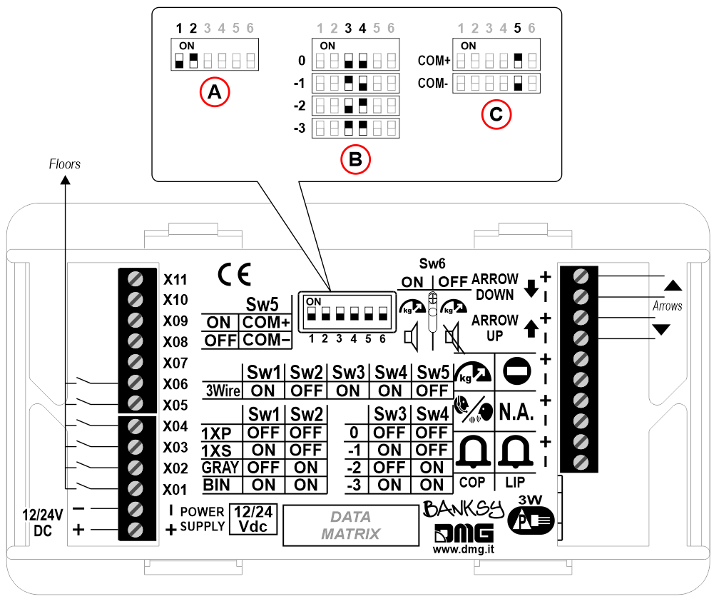
A) – Coding
B) – Offset (-3 ÷ 0)
C) – Common (Inputs)
23 floors max. (-3, 0, 19)
Binary
DB1/DB2
DB3/DB4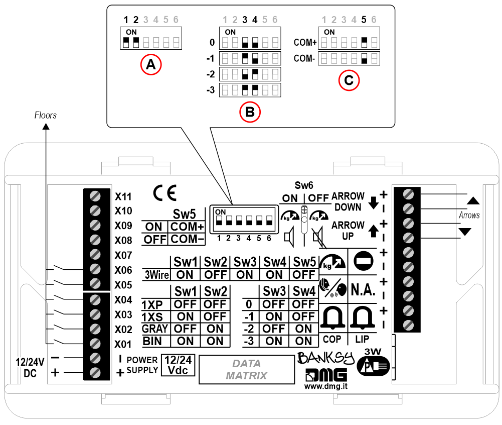
A) – Coding
B) – Offset (-3 ÷ 0)
C) – Common (Inputs)
23 floors max. (-3, 0, 19)
DB1/DB2
DB3/DB4A) – Coding
B) – Offset (-3 ÷ 0)
C) – Common (Inputs)
11 floors max.1 Wire / Segment
DB1/DB2
DB3/DB4A) – Coding
B) – Offset (don’t use the dip-switch to set the offset)
C) – Common (Inputs)
29 floors max. (-9, 0, 19)LETTERS DISPLAYED
Gray
DB1/DB2
DB3/DB4A) – Coding
B) – Offset (-3 ÷ 0)
C) – Common (Inputs)
23 floors max. (-3, 0, 19)Binary
DB1/DB2
DB3/DB4
A) – Coding
B) – Offset (-3 ÷ 0)
C) – Common (Inputs)
23 floors max. (-3, 0, 19)Set up first visualization of lowest floor (Binary coding only)
Set up first visualization of lowest floor (Binary coding only)
DB1/DB2
To show a digit (instead of “blank screen”) at the lowest floor, connect the terminal X11 to the “+” or to the “-” of the power supply, depending on the common setted.
DB3/DB4
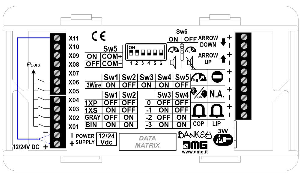
To show a digit (instead of “blank screen”) at the lowest floor, connect the terminal X11 to the “+” or to the “-” of the power supply, depending on the common setted.
To show a digit (instead of “blank screen”) at the lowest floor, connect the terminal X11 to the “+” or to the “-” of the power supply, depending on the common setted.
DB3/DB4
To show a digit (instead of “blank screen”) at the lowest floor, connect the terminal X11 to the “+” or to the “-” of the power supply, depending on the common setted.
Service Messages
Car
DB1/DB2
 A) – Overload (S1)
B) – Communication established (S2)
C) – Alarm sent (S3)
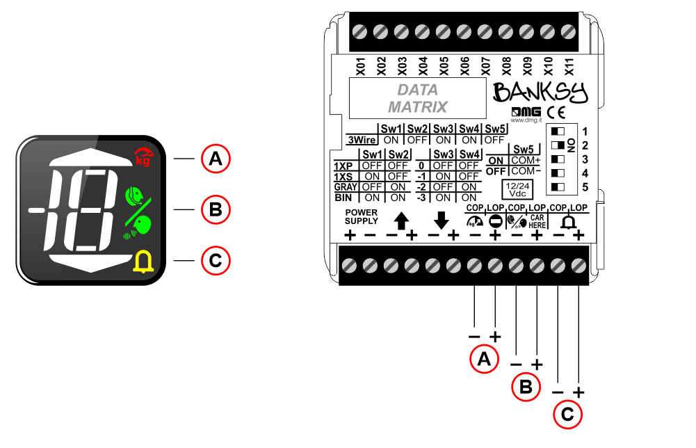
DB3/DB4
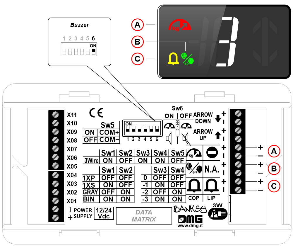
A) – Overload (S1) + enabling the buzzer if the SW6 switch is in the ON position.
B) – Communication established (S2)
C) – Alarm sent (S3)
A) – Overload (S1)B) – Communication established (S2)
C) – Alarm sent (S3)
DB3/DB4
A) – Overload (S1) + enabling the buzzer if the SW6 switch is in the ON position.
B) – Communication established (S2)
C) – Alarm sent (S3)
Floor
DB1/DB2
DB3/DB4
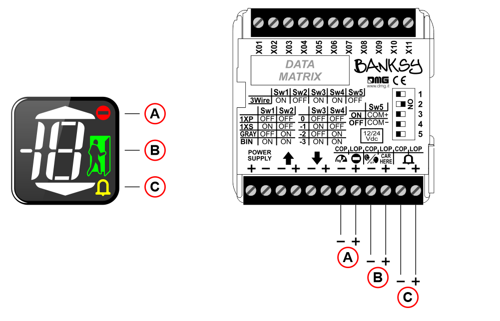
A) – Out of order (S1)
B) – Present (S2)
C) – Alarm (S3)
DB3/DB4
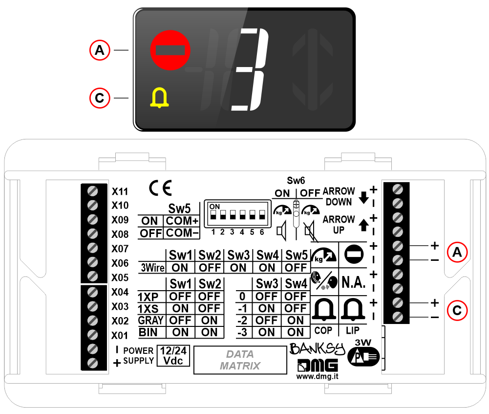
A) – Out of order (S1)
B) – Present (S2)
C) – Alarm (S3)
Film for the CTDB3 capacity plate
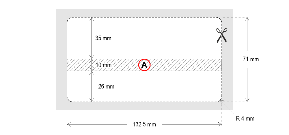
A) Prepared area for emergency lamp (if provided)
Datasheet
| Dimensions (frontal mounting versions only) | DB1: 55×55 mm (H15,15mm from the plate surface) DB2: 68,3×70,8 mm (H12,9mm from the plate surface) DB3: 138,3×76,8 mm (H13,5mm from the plate surface) DB4:147,0×85,5 mm (H13,1mm from the plate surface) |
| Power supply | 12÷24V DC ±10% |
| Power supply (position input) | 12÷24V DC ±10% |
| Power supply (arrows) | 12÷24V DC ±10% (optoisolated) |
| Absorption | DB1/DB2 7mA per segment (12V) – 10mA per segment (24V) Arrows UP/DW: 14mA (12V) – 20mA (24V) Inputs S1/S3: 10mA (12V) – 21mA (24V) Inputs S2: 10mA (12V) – 48mA (24V) DB3/DB4 7mA per segment (12V) – 9mA per segment (24V) Arrows UP/DW: 22mA (12V) – 22mA (24V) Inputs S1: 11mA (12V) – 18mA (24V) Inputs S2: 10mA (12V) – 17mA (24V) Inputs S3: 8mA (12V) – 17mA (24V) Buzzer: 14mA (12V) – 15mA (24V) |
| Operating temperature | -10°C ÷ +50°C |
| Degree of protection | IP4x (frontal mounting only) |
Download
| Reference | Version | Link |
|---|---|---|
| 1.3 | Download PDF (English) | |
| New version DB4 | 1.4 | Download PDF (English) |
| Set up first visualization | 1.5 | Download PDF (English) |
| Special back mounting version | 1.6 | Download PDF (English) |
| Added mounting with emergency lamp and gong | 1.7 | Download PDF (English) |
| Instructions for the capacity plate film | 1.8 (current version) | Download PDF (English) |