
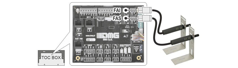
Magnetic readers (FAI / FAS)
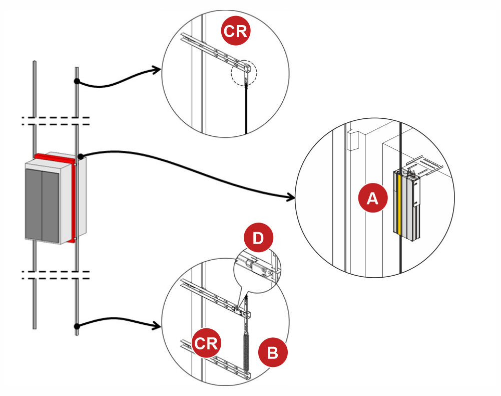
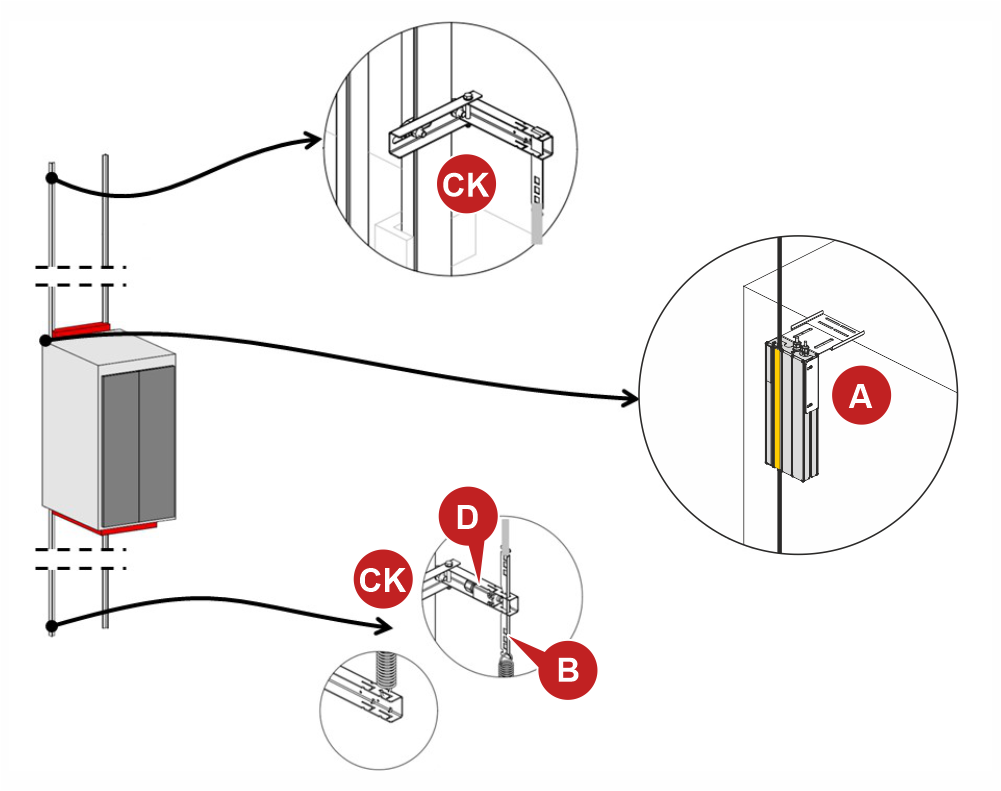
This counting system consists of two magnetic readers (FAI-FAS) with a normally open contact mounted on two brackets positioned on the top of cabin, and a set of magnets positioned on the elevator rails.
This counting system can be used when the system’s characteristics meet the following conditions:
1) Floor-to-floor distances of less than 0,4 meters (short floors)
2) Floor-to-floor distances greater than 1,8 meters
3) Speed < 0.8 m/s
Installation

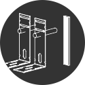
Case A : Elevators with frame mechanics
Case B : Elevators with backpack mechanics
Accessories for special cases
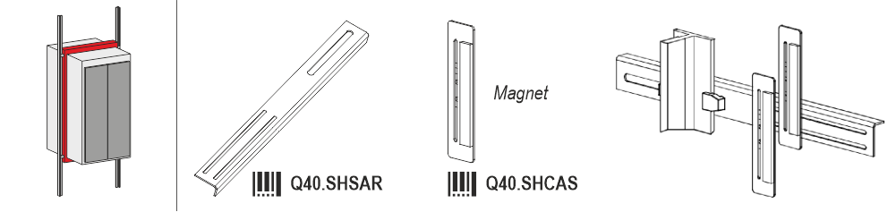
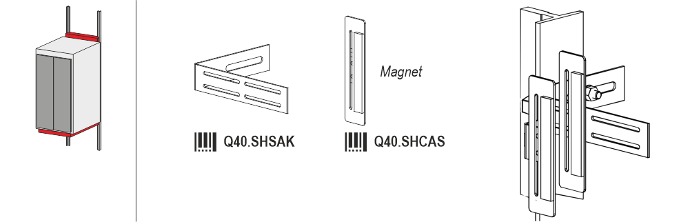
Positioning magnets on elevator guides
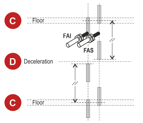
C) Floors
D) Deceleration
Wirings
The Magnetic readers are connected directly to the TOC box (top of cabin)

Motor encoder
This counting system can only be used on systems with speeds below 2m/s and without open-door maneuvers; it is suitable only for the following optional boards for Gearless motors with closed-loop systems:
OPC-PR Q40.SCLSC – Encoder Sin Cos
OPC-PS Q40.SCLFL – Encoder En Dat
OPC-PSH Q40.SCLSCH – Encoder Sin Cos+Hiperface
The controller processes the signals transmitted by the OPC boards, converting the pulses into a count.
This counting system has an accuracy of approximately 1 millimeter.

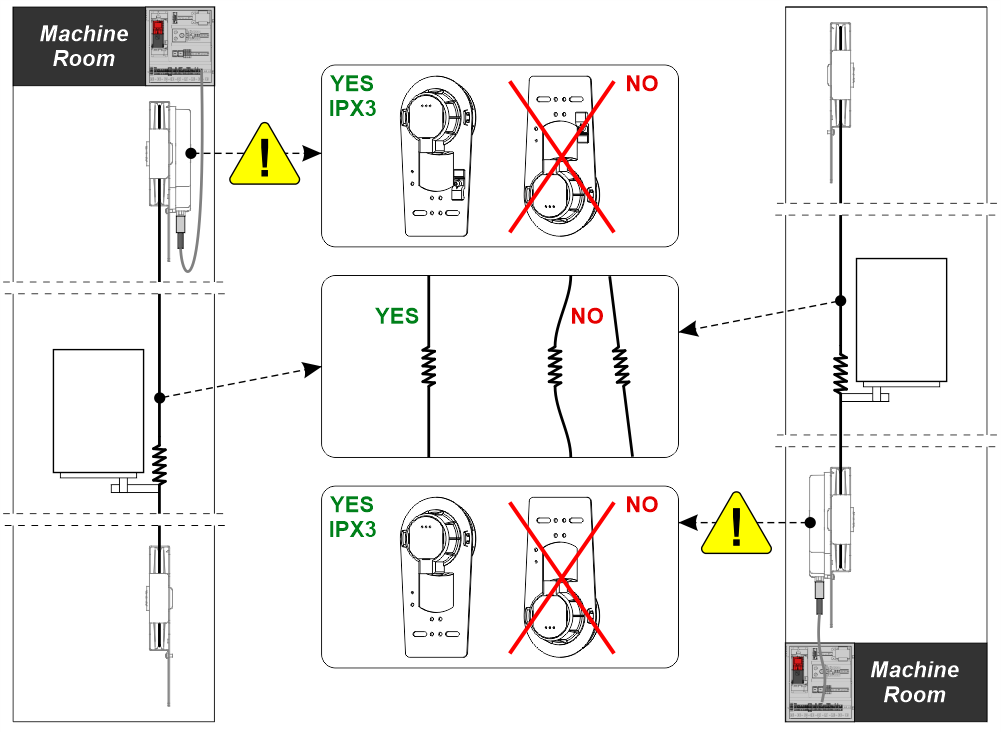
DMG rope magnetic encoder
The new DMG magnetic encoder uses a sensor to detect the rotation and position of a magnet placed on the encoder pulley axle. The pulses generated are received and processed by the lift control panel which calculates the position, direction and speed of the car.
Installation
Advice and warnings
The pulley embedding the Encoder must be installed in the top of the shaft or in the pit, close to the machine room.
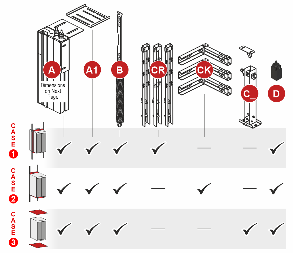
System components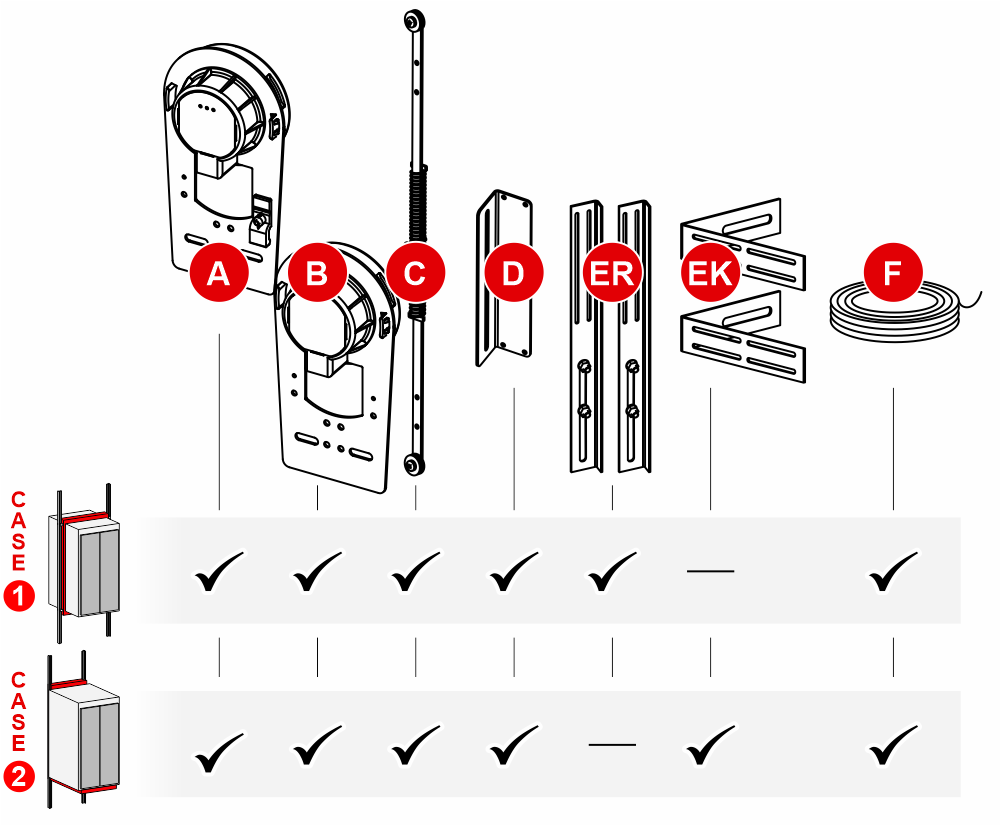
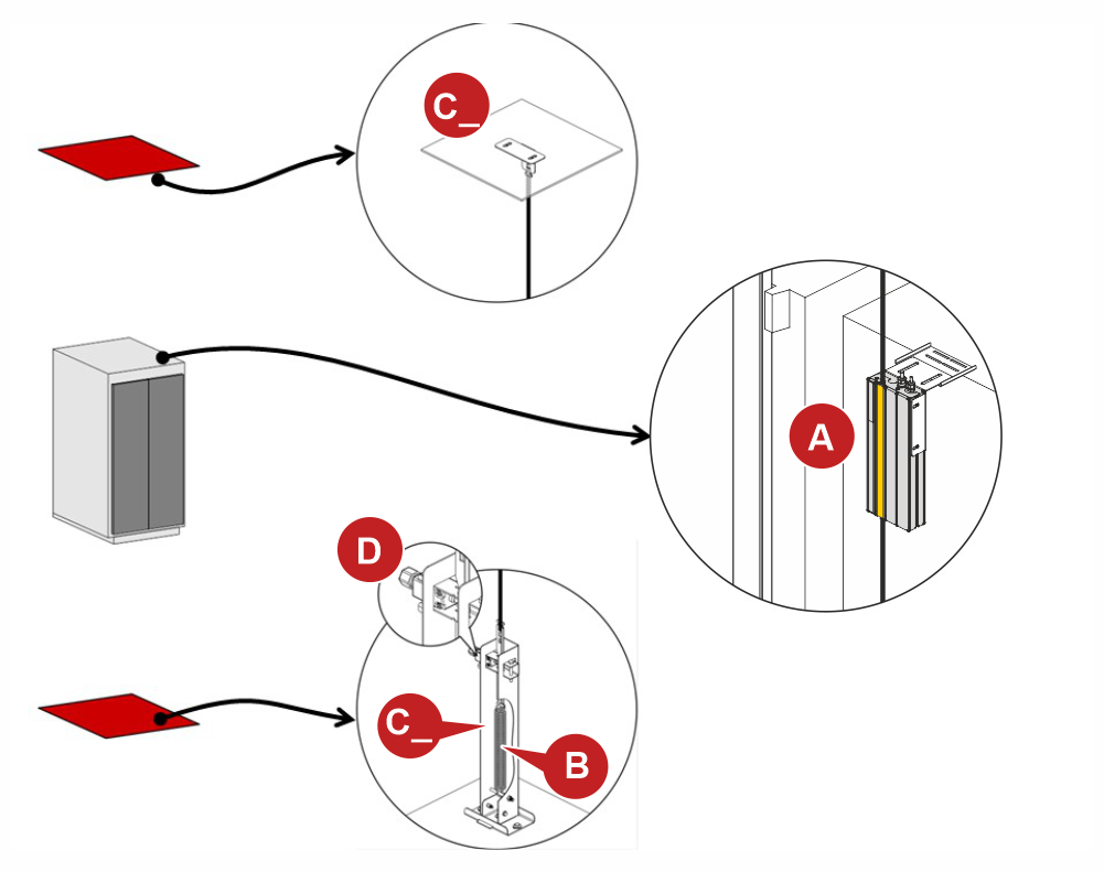
Case 1 : Elevators with frame mechanics
Case 2 : Elevators with backpack mechanics
A) – It is the Encoder pulley that contains the electronic card. It can have 2 resolutions:
– 1.25 mm (100 PPR) for the red labeled encoder: To be used with the Pitagora 4.0 controller starting from firmware version 3.0.2
– 2.5 mm (50 PPR) for the blue labeled encoder: To be used with the V3 / Musa / Pitagora 4.0 controllers up to Firmware Y version
C) – The spring tensioner can also be mounted on the top of cabin as needed.
Mounting
Mounting depends on the mechanics of the installation.
Case 1 – Elevators with frame mechanics
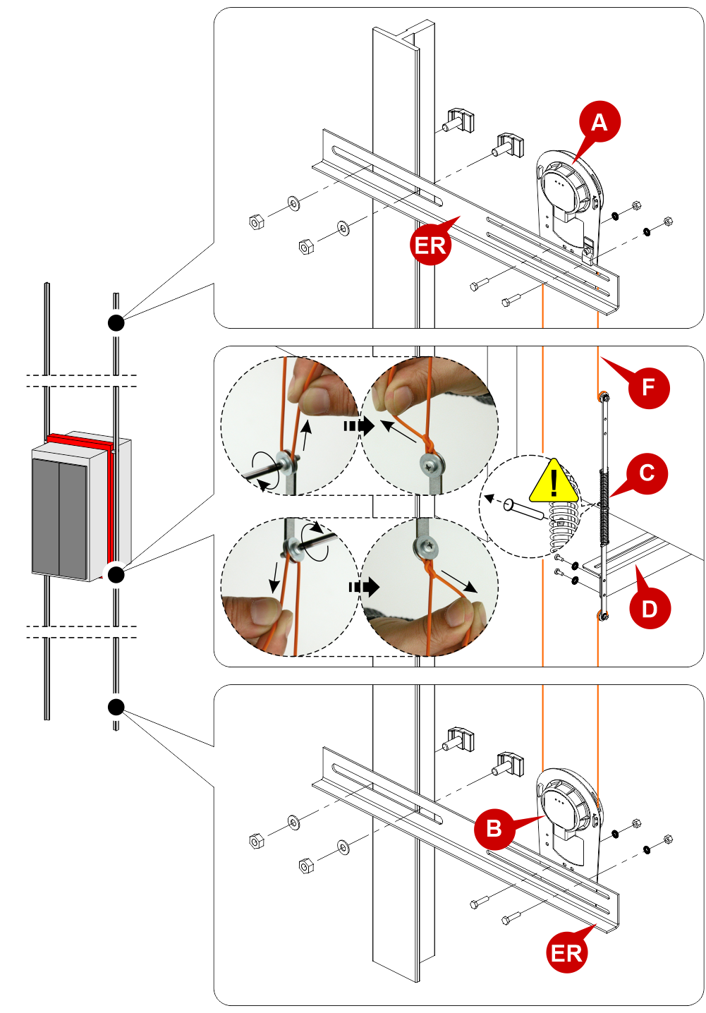
C) – The spring tensioner can also be mounted on the top of cabin as needed.
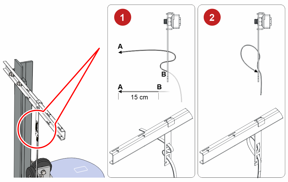
![]() Remove the retainer only after the installation is complete.
Remove the retainer only after the installation is complete.
In case of replacement on old systems, it will be necessary to untie the old rope and re-tension it after assembling the new encoder.
Case 2 – Elevators with backpack mechanics
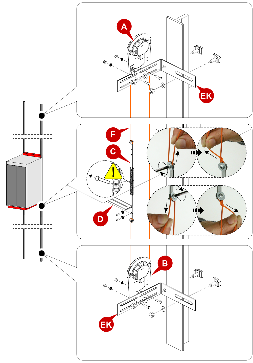
C) – The spring tensioner can also be mounted on the top of cabin as needed.
![]() Remove the retainer only after the installation is complete.
Remove the retainer only after the installation is complete.
In case of replacement on old systems, it will be necessary to untie the old rope and re-tension it after assembling the new encoder.
Wirings
Connection to Pitagora 4.0 controller
– Starting from firmware version 3.0.2 –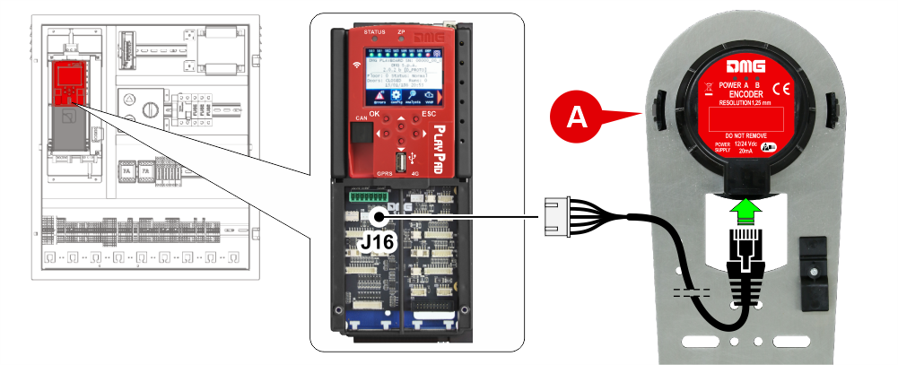 A) – Encoder with 1.25 mm resolution
– Up to firmware version 3.0.1 –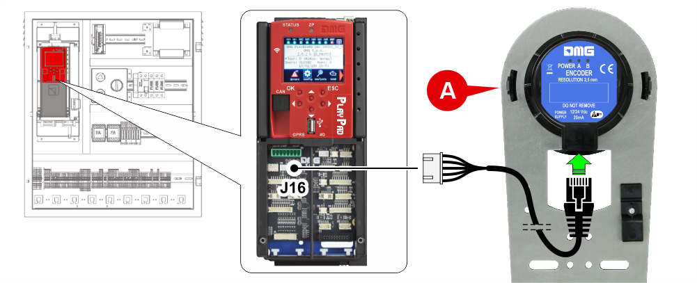 A) – Encoder with 2.50 mm resolution
Connection to existing MUSA / PLAYBOARD V3 controllers
A) – Encoder with 2.50 mm resolution
You can replace the existing rope encoder with the new magnetic encoder (2,50 mm resolution).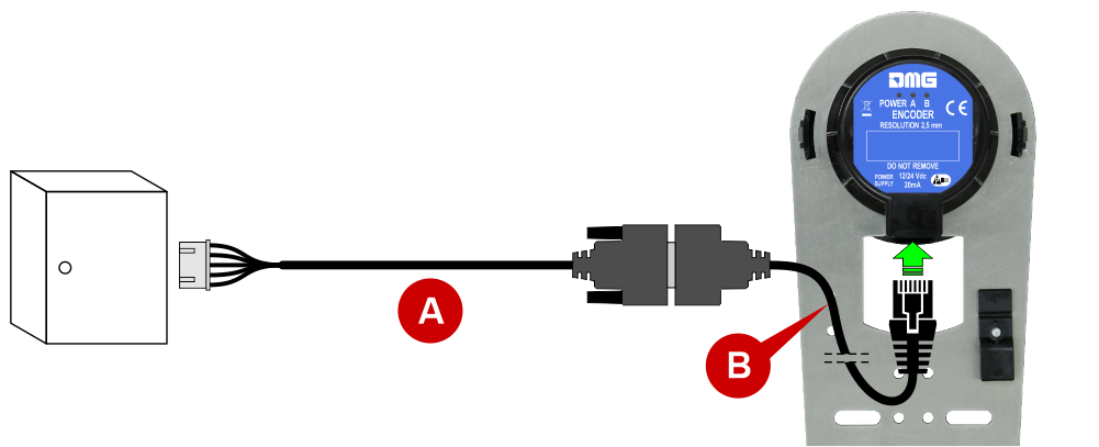
Just leave the existing cable (A) and connect it to the new encoder by means of an adapter cable (B).
After replacing the encoder, check:
- The correct direction of rotation in inspection mode (up movement, increase in mm, down movement, decrease in mm). If necessary, change the direction of rotation from the controller by following these instructions:
- Set the panel in Temporary operations (Configuration menu -> Temporary operations -> Yes);
- Change the rotation in the System Positioning menu -> Positioning System -> clockwise/counterclockwise encoder;
- Remove the Temporary operations (Configuration menu -> Temporary operations -> No).
- Check the correct alignment of the car on all floors. If necessary, adjust the stopping accuracy from the controller in the System Positioning menu -> Floor position.
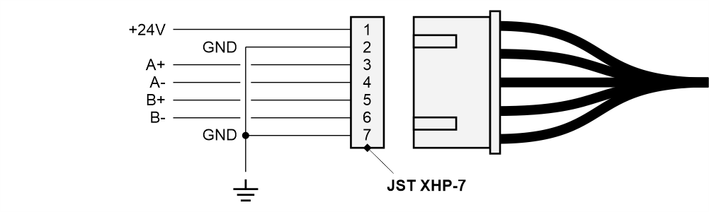
PIN OUT JST 7 poles connector
Diagnostics LED
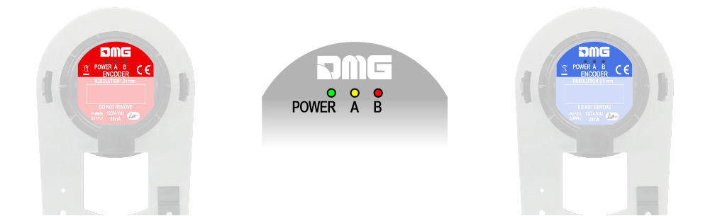
POWER: If the LED is on, the encoder is powered.
A/B: Status of encoder outputs. With the lift car stationary there is no change in the status of these LEDs (they can be both ON and OFF); with the lift car in motion the LEDs will both be ON.

Absolute encoder (ELGO LIMAX 33 CP)
The absolute encoder allows you to replace all the safety contacts inside the lift shaft. The position of the cabin is detected thanks to a magnetic strip.
Installation
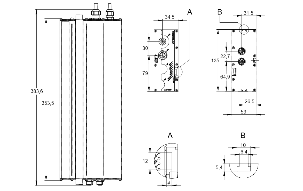
Dimensions:
System components
Case 1 : Elevators with frame mechanics
Case 2 : Elevators with backpack mechanics
Case 3 : Ground and ceiling fixing
Mounting
Case 1 – Elevators with frame mechanics
Case 2 – Elevators with backpack mechanics
Case 3 – Ground and ceiling fixing

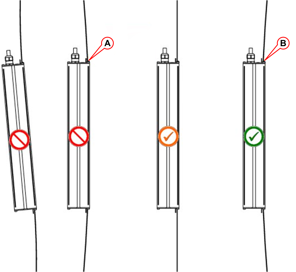
Be careful to position the magnetic strip as shown in the figures below.
Correct positioning of the Magnetic Tape![]() Remove all the magnets in the compartment before installing the magnetic tape.
Remove all the magnets in the compartment before installing the magnetic tape.
Do not install the magnetic tape near permanent magnet motors.
Do not use magnetized tools near the Magnetic tape.
Do not use welding equipment near the magnetic tape.
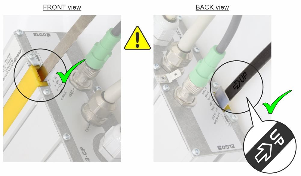
Respect the fitting shown on the tape and make sure it is in the correct position shown in the following figure:
A) – Tape touches the guide with the magnetized side.
B) – Tape touches the guide with the steel side.
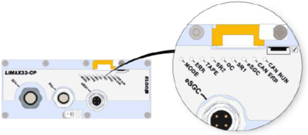
LED Signal on the device
| LED | DESCRIPTION | |
|---|---|---|
| MODE | Normal mode | Slow Flashing (1 s) |
| Pre-Commissioning Mode | Fast Flashing (0,1 s) | |
| Teach Mode | Lights permanently | |
| ERROR | No Error | Led OFF |
| Generic Error | Led ON | |
| Emergency Error | Flashing | |
| TAPE | Magnetic Tape not detected | Led ON |
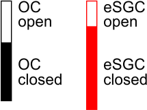
| eSGC | eSGC Contact close | Led ON |
| eSGC Contact Open | Led OFF | |
| OC | OC Contact close | Led ON |
| OC Contact Open | Led OFF | |
| SR1 | SR1 Contact close | Led ON |
| SR1 Contact Open | Led OFF | |
| SR2 | SR2 Contact close | Led ON |
| SR2 Contact Open | Led OFF | |
| CAN-ERR | Status CAN Open | Led ON |
| CAN-RUN | Status Can Open | Led OFF |
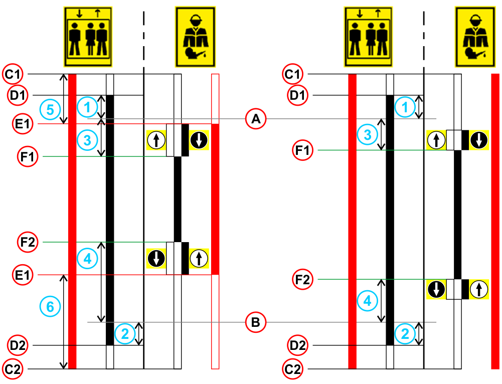
Explanation of safety contacts
| Reduced Head and/or Reduced PIT Installation | Sufficient Head and Pit clearance according EN81-20 §5.2.5.7 / § 5.2.5.8 |
||
|---|---|---|---|
 |
|||
 | Normal Mode | A) - | TOP floor |
 | Inspection Mode | B) - | BOTTOM floor |
 | Safety contacts status | C1) - | Upper reference position |
| Inspection UP button | C2) - | Lower reference position | |
| Inspection DOWN button | D1) - | Upper final limit switch | |
| Final limit switches Offset Up | D2) - | Lower final limit switch | |
| Final limit switches Offset Down | E1) - | Upper pre-triggered stopping system limit | |
| Inspection limit switches Offset Up | E2) - | Lower pre-triggered stopping system limit | |
| Inspection limit switches Offset Down | F1) - | Upper inspection limit switch | |
| Pre-Triggered Stopping System Offset Up | F2) - | Lower inspection limit switch | |
| Pre-Triggered Stopping System Offset Down | |||
For manual adjustment of the positions of the indicated is possible from menu <Positioning> Monitor Encoder (see table below).
| Label | Page | Description | |
|---|---|---|---|
| N_LIM_S | 7 | Upper final limit switch offset (offset over top floor) | |
| N_LIM_D | 7 | Lower final limit switch offset (offset under bottom floor) | |
| I_LIM_S | 6 | Upper inspection limit switch (offset under top floor) | |
| I_LIM_D | 6 | Lower inspection limit switch (offset over bottom floor) | |
| TRIPS | 8 | Upper Pre-Triggered Stopping System limit (from Upper Reference Position) | |
| TRIPD | 8 | Lower Pre-Triggered Stopping System limit (from Lower Reference Position) |
TRIPS and TRIPD values are used only if ELGO is part of Safety System for Reduced Head and/or Pit (ELGO + eSGC).
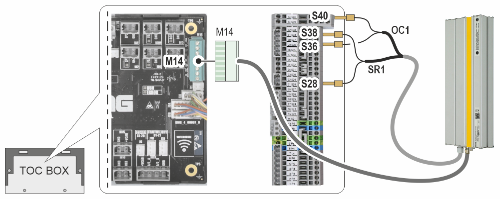
Wirings
Connection to Pitagora 4.0 controller
The ELGO encoder is connected directly to the TOC box (top of cabin)
Video tutorial
English language
Italian language