(v 1.0)
Safety and usage cautions
Before installing our products, we recommend you to consult the section about safety and usage cautions at the link below.

Mounting
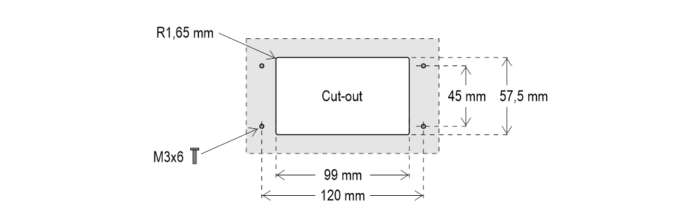
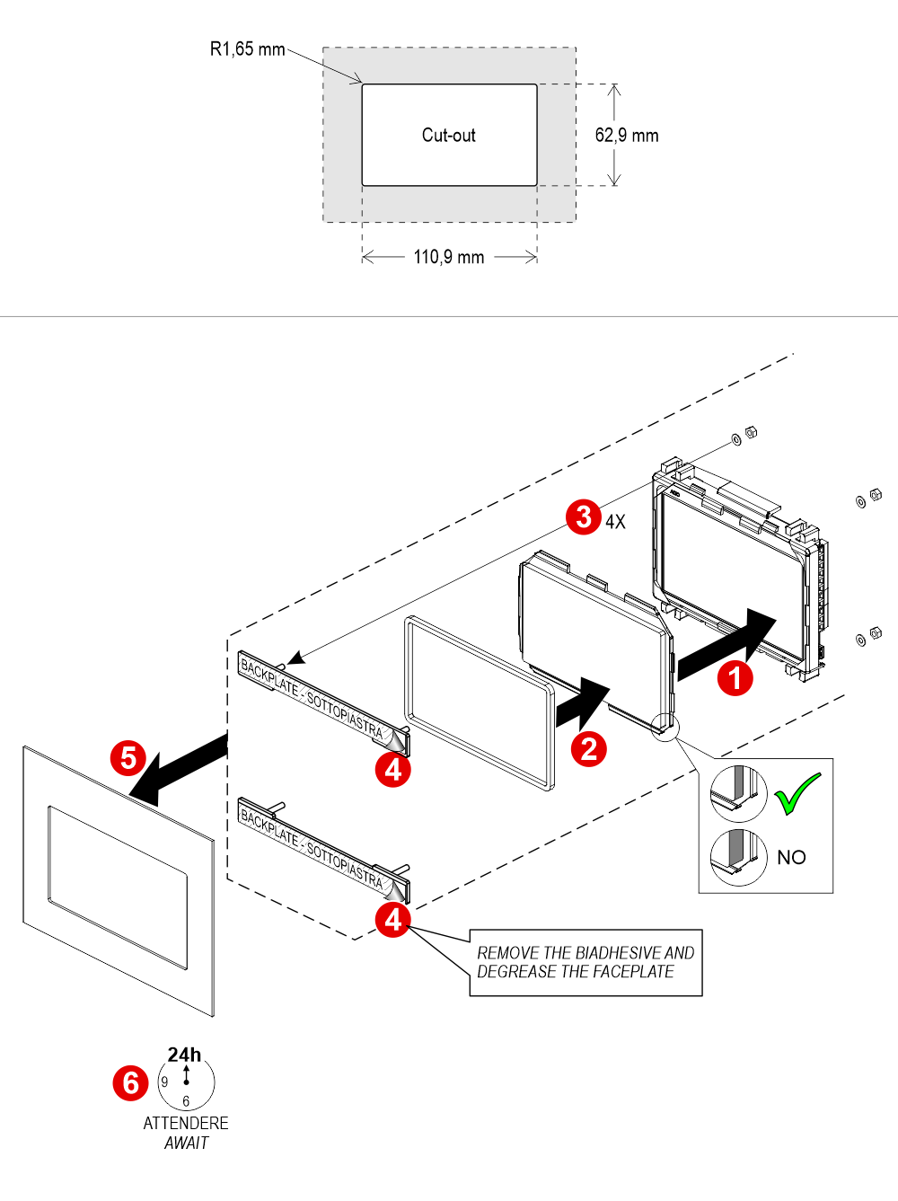
Raffaello 4.3″
With welded pins on 1,5/3 mm pushbutton panel
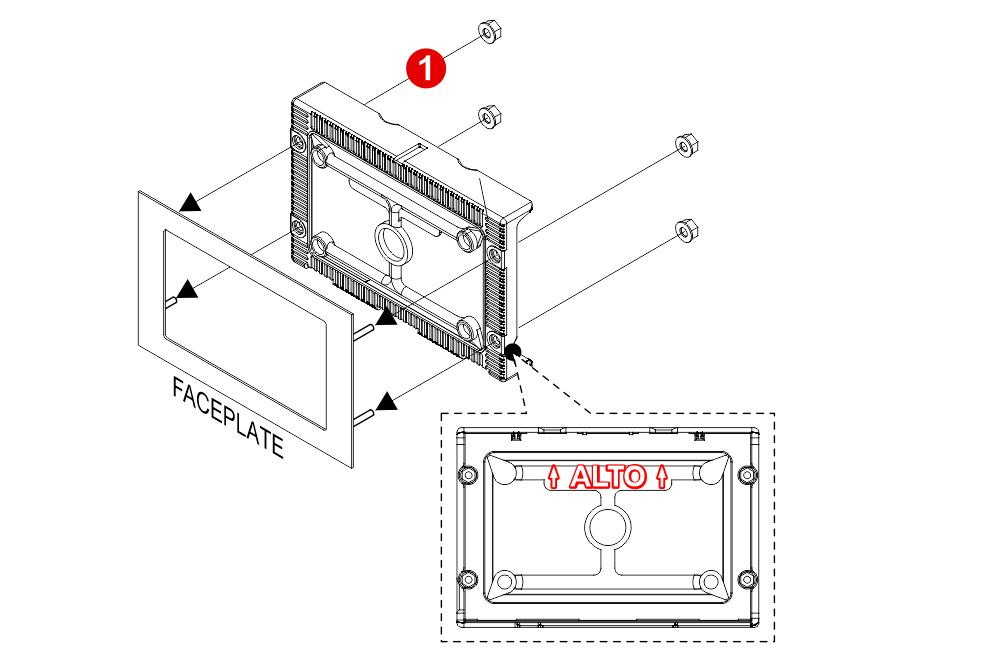
 If you are replacing an existing position indicator, please verify that studs’ length is ≤ 8mm; if not, shorten them.
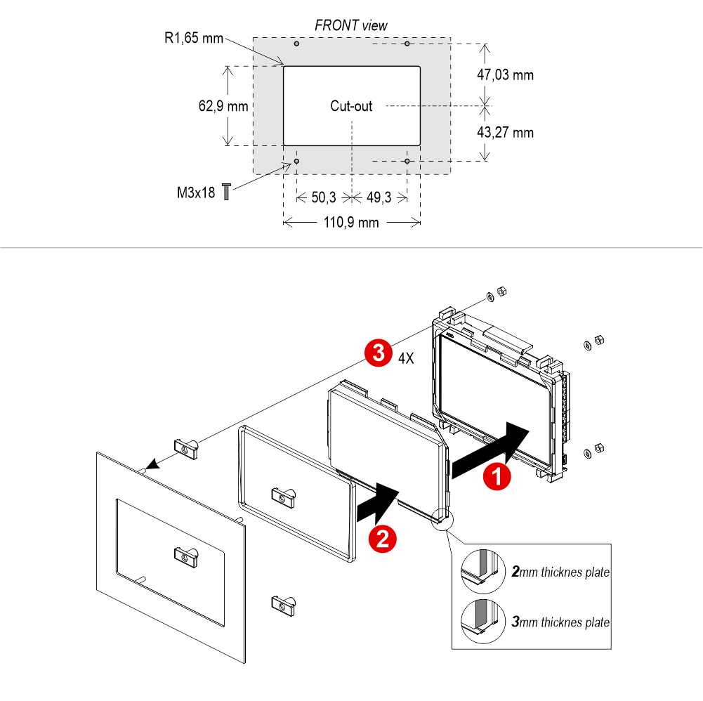
If you are replacing an existing position indicator, please verify that studs’ length is ≤ 8mm; if not, shorten them.Raffaello 4.3″ (EN81-71)
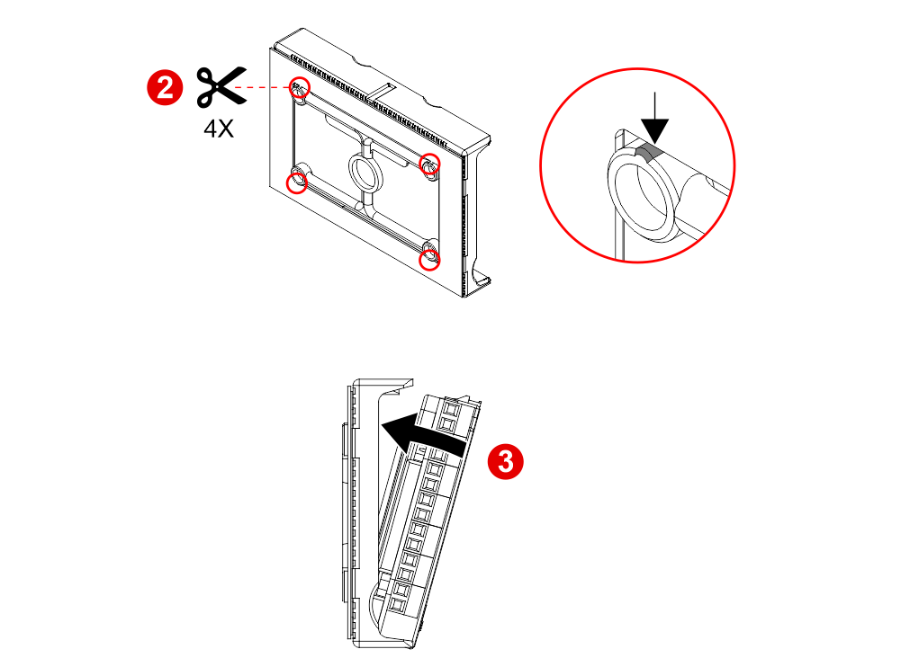
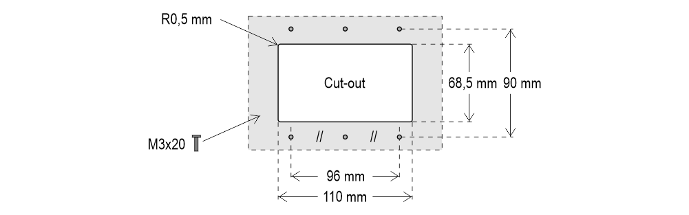
With welded pins on 2/3 mm pushbutton panel
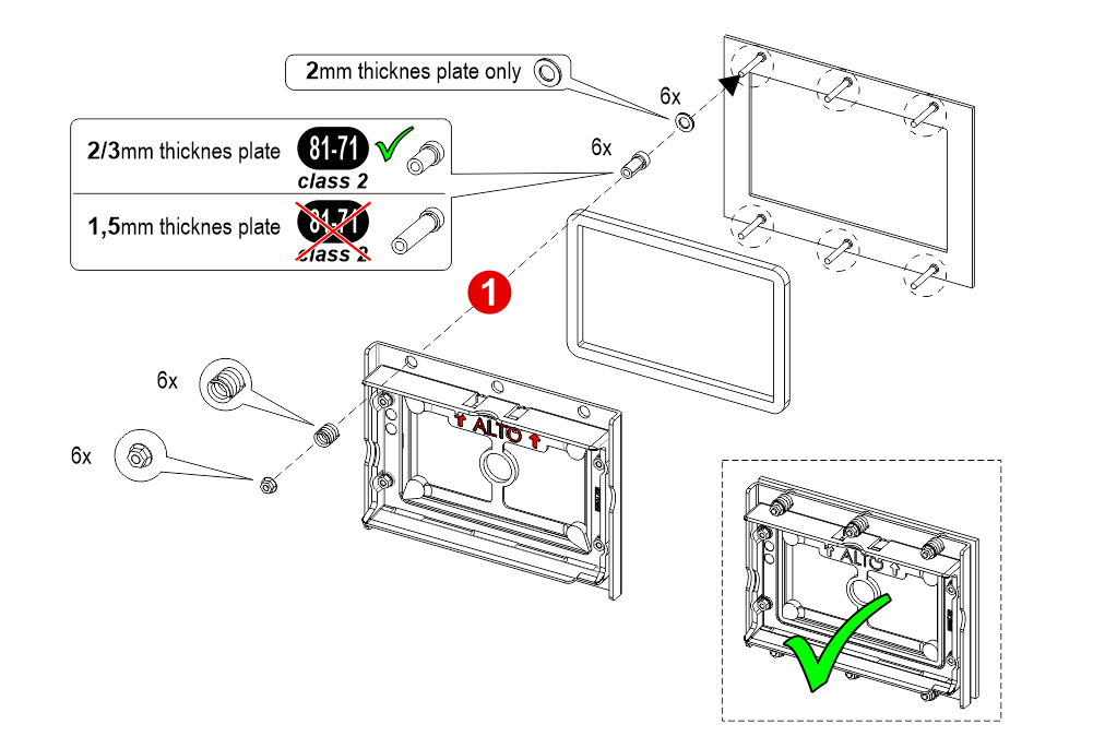
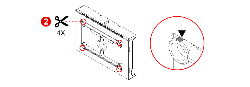
 If you are replacing an existing position indicator, please verify that studs’ length is ≤ 8mm; if not, shorten them.
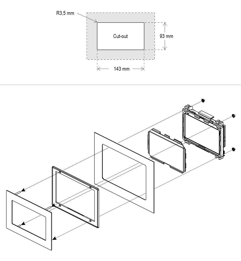
If you are replacing an existing position indicator, please verify that studs’ length is ≤ 8mm; if not, shorten them.Raffaello 5″
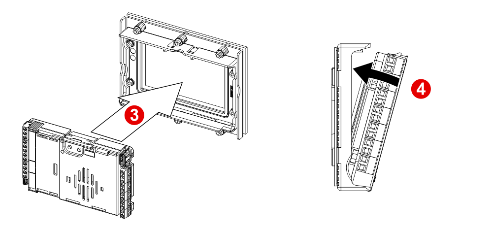
With welded pins on backplate (for 1/1,5 mm pushbutton panel)
 With welded pins on 2/3 mm pushbutton panel
Frontal mounted on 1/2 mm pushbutton panel
With welded pins on 2/3 mm pushbutton panelFrontal mounted on 1/2 mm pushbutton panel
Wiring Instructions
Wiring of position and direction inputs
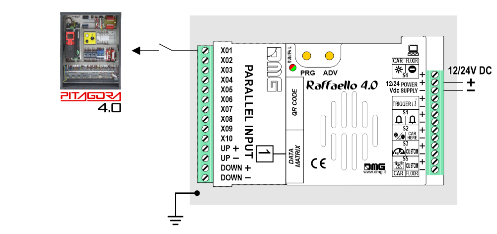
Pitagora 4.0
DMG CAN serial protocol
CAR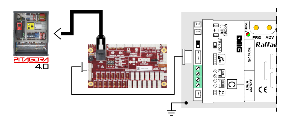
FLOOR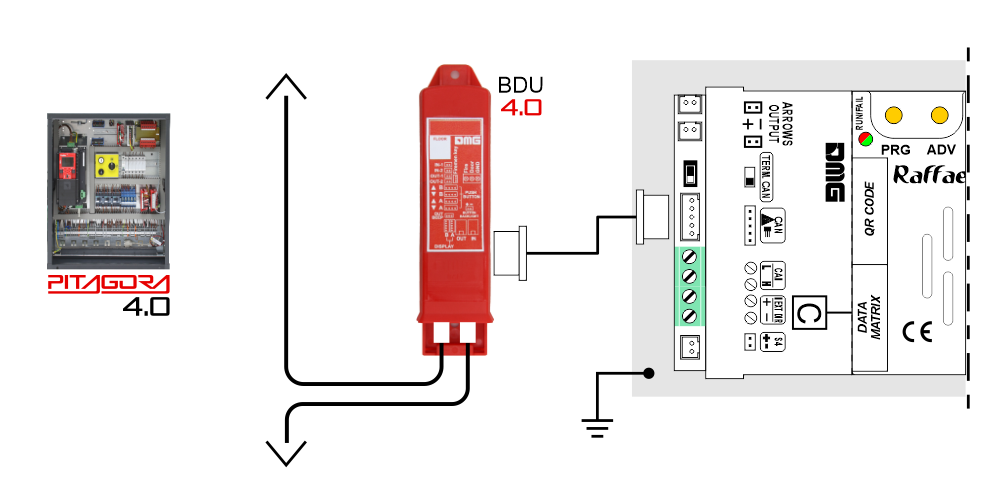
DMG
3-wires serial
CAR
FLOOR
DMG
3-wires serial
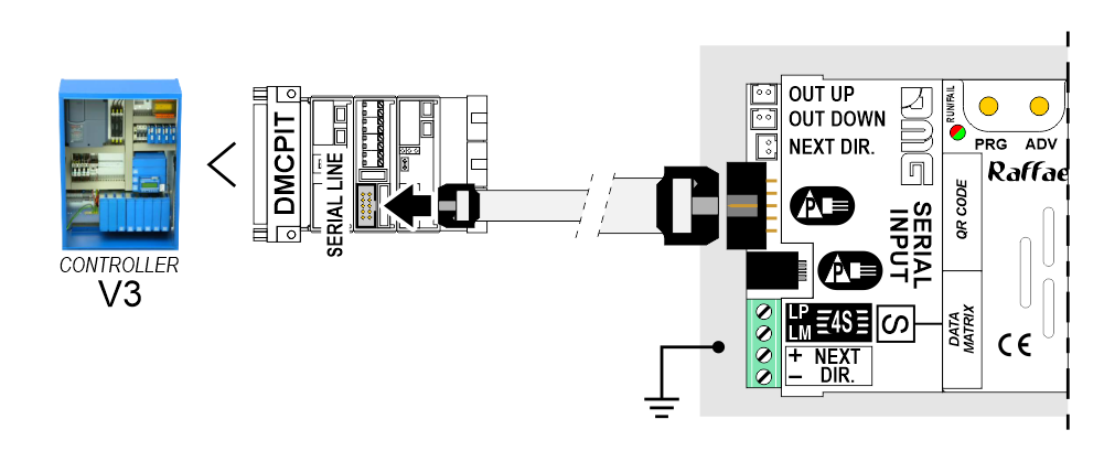
Pitagora V3
CAR
 FLOOR
FLOOR
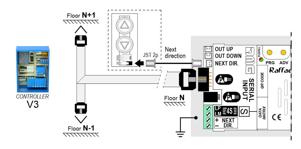
FLOOREncoder DEUM
 For more details please refer to the Encoder DEUM support page
DMG CAN serial protocol
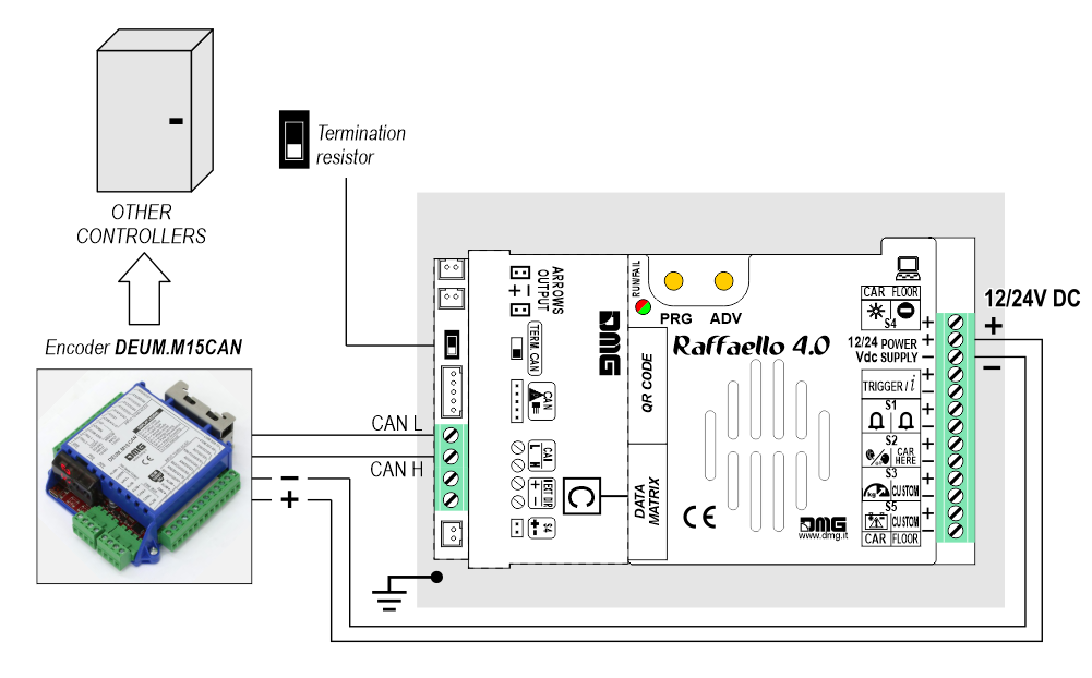
DMG
3-wires serial
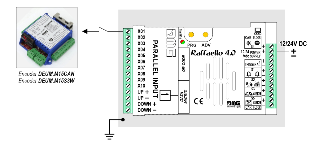
DMG
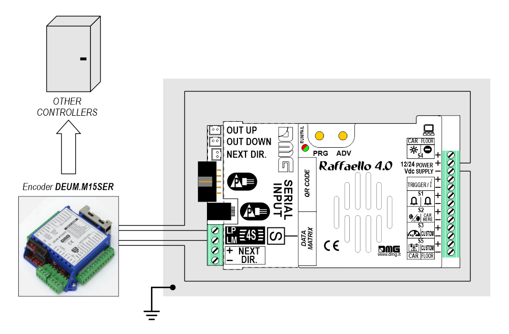
RS485 serial
Autonomous Positioning System
The Autonomous Positioning System for the DMG displays of the Raffaello, Giotto and Matisse series, allows to show the lift position and direction independently from the lift control panel. The interface uses the sensors signals installed on the top of car.
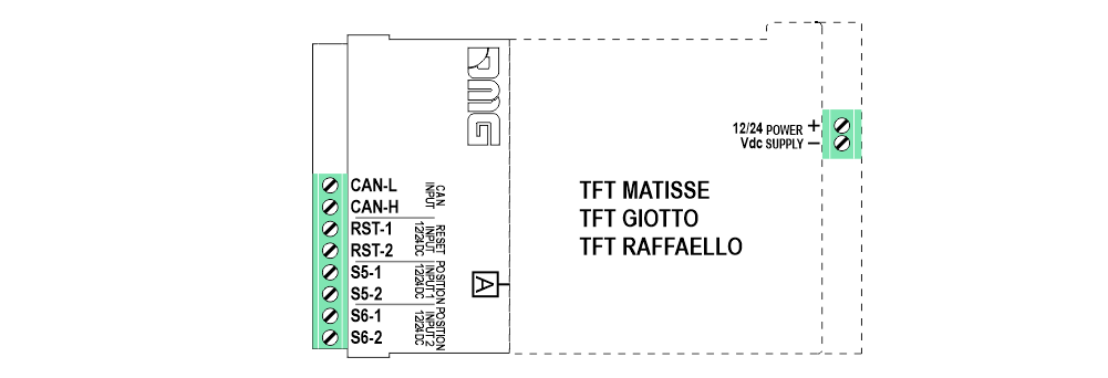
If available, it is possible to use the same position sensors used by the controller.
If NOT available, you have to install:
• 1 NO magnetic sensor on the cabin + 1 magnet at every floors for counting position.
• 1 NO/NC magnetic sensor on the cabin + 1 magnet at main floor for the RESET.
In this interface there is a CAN BUS serial line for piloting the position indicators of floor.
For all other functions (Voice Synthesizer, gong, indicators, etc.) please refer to the display technical support page.
Autonomous positioning System
If available, it is possible to use the same position sensors used by the controller.
If NOT available, you have to install:
• 1 NO magnetic sensor on the cabin + 1 magnet at every floors for counting position.
• 1 NO/NC magnetic sensor on the cabin + 1 magnet at main floor for the RESET.
In this interface there is a CAN BUS serial line for piloting the position indicators of floor.
For all other functions (Voice Synthesizer, gong, indicators, etc.) please refer to the display technical support page.
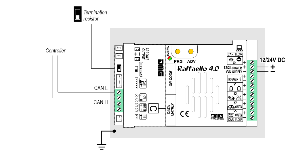
Autonomous positioning System
Other Controllers
Proprietary CAN protocol
1 Wire / Floor
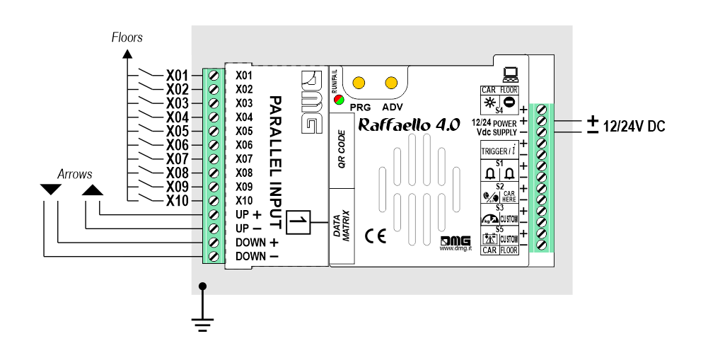 10 floors max.
1 Wire / Segment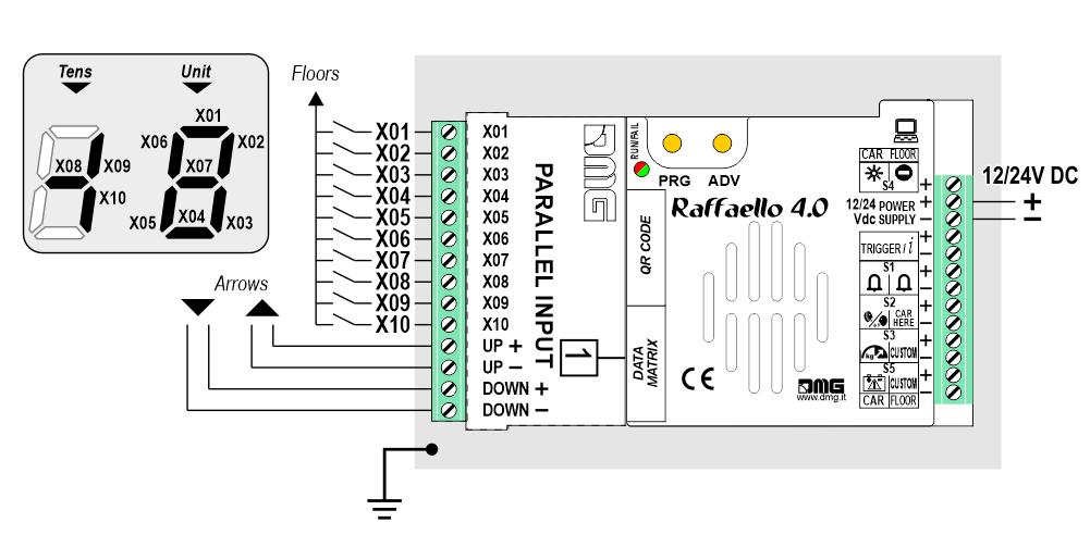 29 floors max. (-9, 0, 19)
Gray / Binary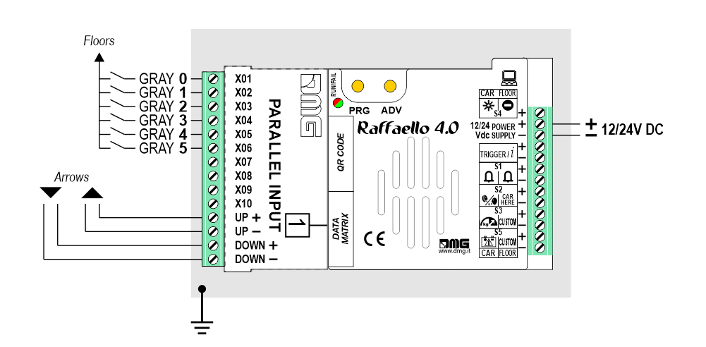 72 floors max. (-9, 0, 62)
TKE/MEA/Autinor
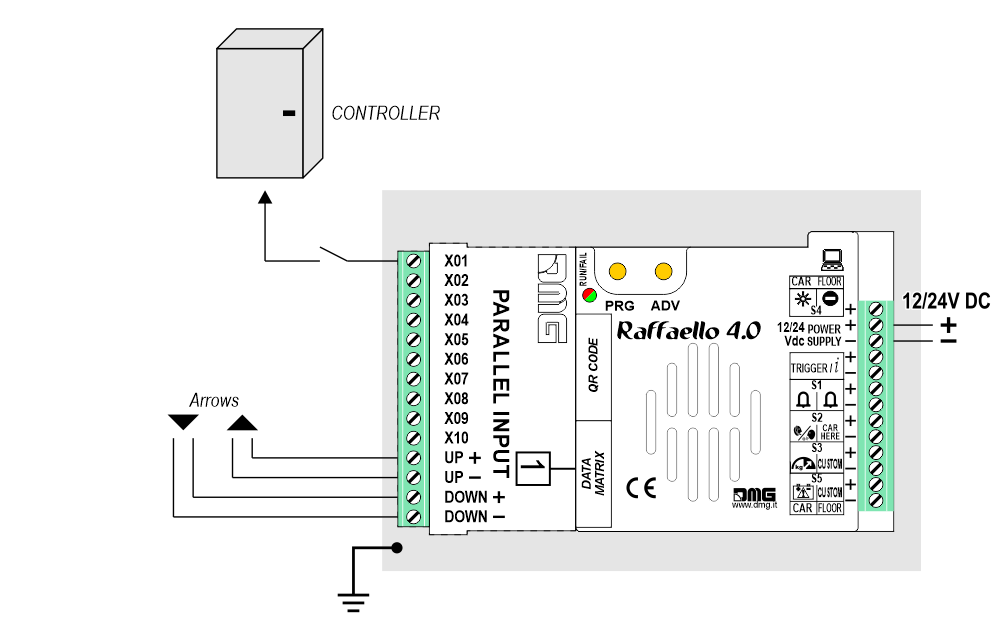
1 Wire / Floor
10 floors max.1 Wire / Segment
29 floors max. (-9, 0, 19)Gray / Binary
72 floors max. (-9, 0, 62)TKE/MEA/Autinor
SERVICE MESSAGE Wiring
CAR
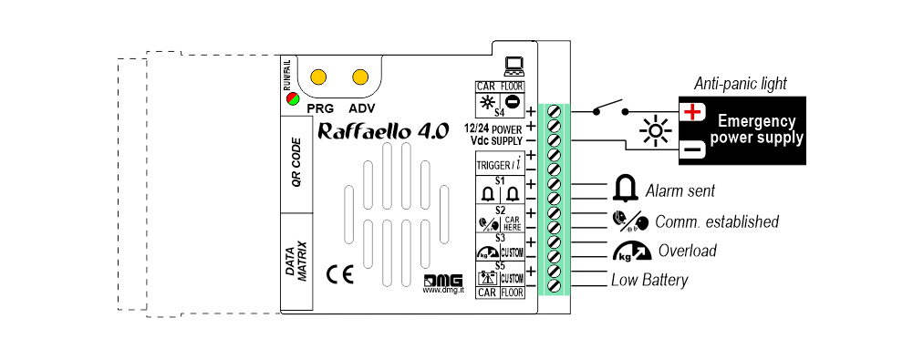
FLOOR
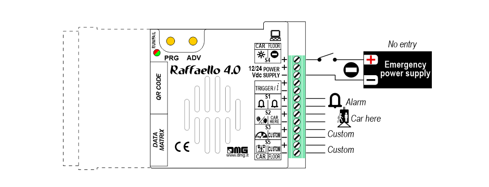
Service messages can also be piloted, through serial bus, by the DMG controller or DEUM.M15 encoder.
TRIGGER Wiring
This input triggers the gong.
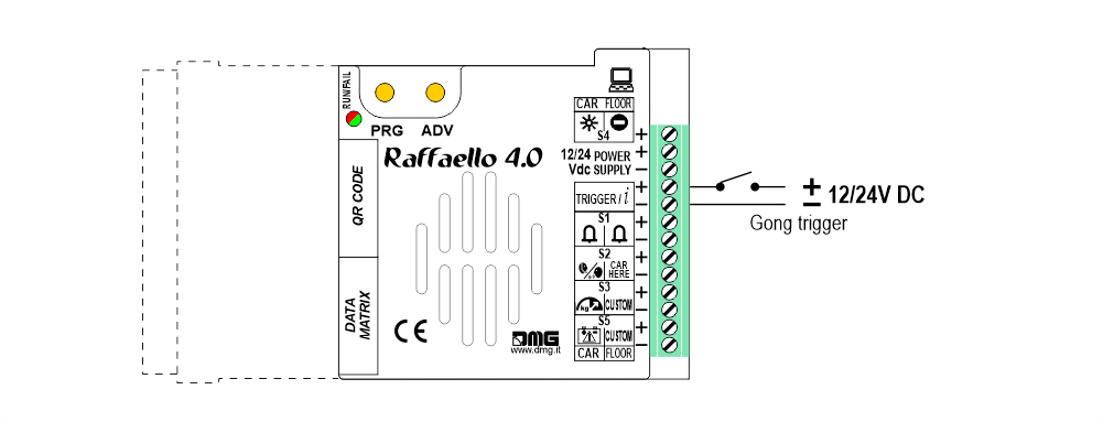
![]() If piloting is driven by DEUM ENCODER, a direct connection between the TRIGGER command and the Encoder is suggested.
If piloting is driven by DEUM ENCODER, a direct connection between the TRIGGER command and the Encoder is suggested.
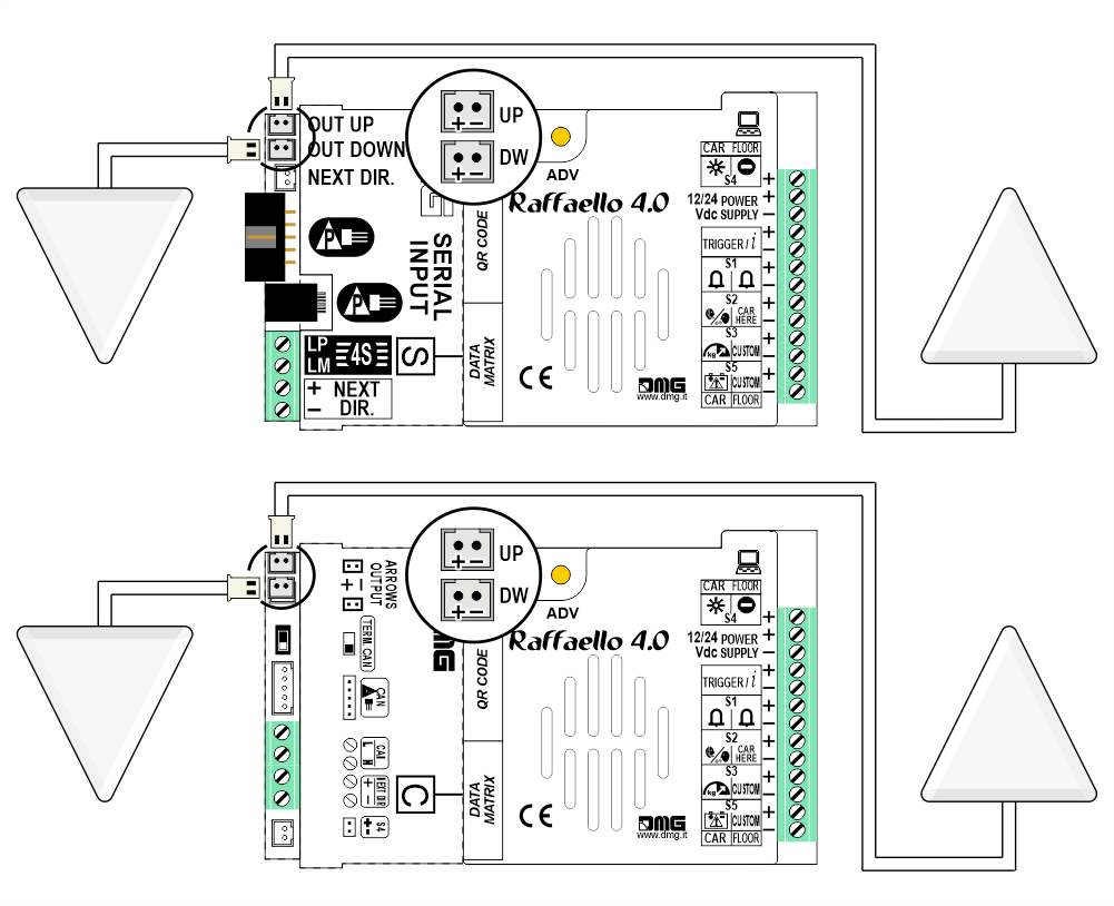
External Arrows Wiring
Settings
 Setup Key Setup Key |  Exit / Back Exit / Back |  Access Menu Key Access Menu Key |  Value setting (>3 sec.) Value setting (>3 sec.) |
General
| MENU | MENU ITEM | AVAILABLE CHOICES | INPUTS | ||||
|---|---|---|---|---|---|---|---|
| Serial / Pitagora | Parallel | CANBUS | |||||
| Input | Serial / 1 wire per floor / segment Gray / Binary / Pos.Sensor TKE / MEA / Autinor / CAN DMG | • | • | • | |||
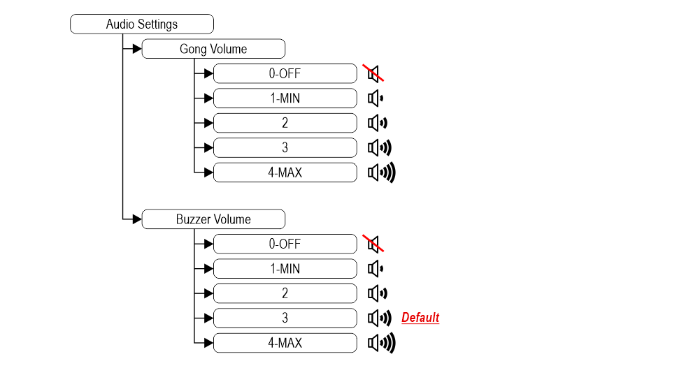
| Audio Settings | Gong Volume | 0-OFF / 1-MIN / 2 / 3 / 4-MAX | • | • | • | ||
| Buzzer Volume | 0-OFF / 1-MIN / 2 / 3 / 4-MAX | • | • | • | |||
| Options | Interface Options | Display Configuration | COP / LOP / LIP | • | • | • | |
| Arrow Configuration | Direction / Next Dir. | • | |||||
| Car at Floor | No / Yes | • | |||||
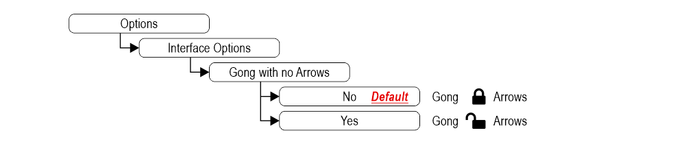
| Gong with NO Arrows | No / Yes | • | |||||
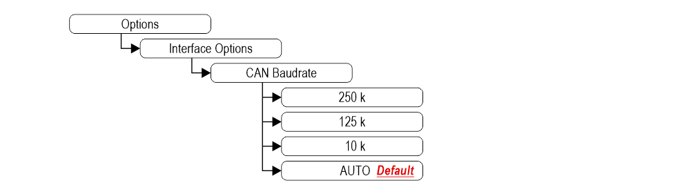
| CAN Baudrate | 250k, 125k, 10k, Auto | • | |||||
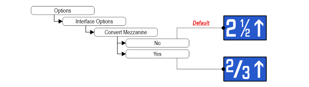
| Convert Mezzanine | No / Yes | • | |||||
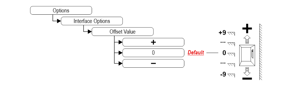
| Offset Value | -9 / ... / 0 / ... / +9 | • | |||||
| First Visualization | Blank / Zero | • | |||||
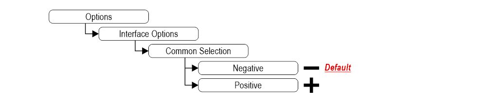
| Common Selection | Negative / Positive | • | |||||
| Arrow Type | Fixed arrows / Scrolling arrows | • | |||||
| Enable AUX Signals | 10 + 0 / 6 + 4 | • | |||||
| Input Filtering | 0 ... 20 | • | |||||
| Gong from Arrows | No / Yes | • | |||||
| Screensaver timer | Disabled / 10-20 / 30-60 / 60-120 | • | • | • | |||
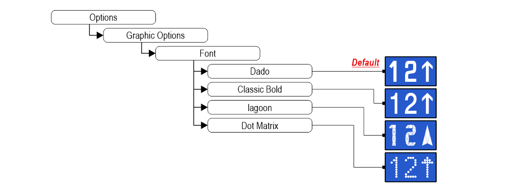
| Graphic Options | Font | Dado / Classic Bold / Lagoon / Dot Matrix | • | • | • | ||
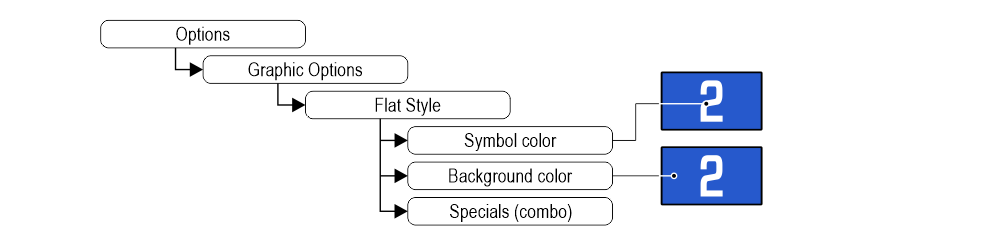
| Flat Style | Symbol color | White / Red / Orange / Blue / Gray / Black | • | • | • | ||
| Background color | Black / Pacific Blue / Navy Blue / Reef Blue / Light Gray /White / Orange / Red | • | • | • | |||
| Specials | White-Green / White-Lilac / Purple-Yellow / White-Gray | • | • | • | |||
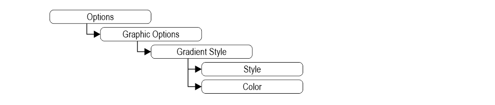
| Gradient Style | Style | Black & White / Red Passion / Gray Goose / Blue Shades | • | • | • | ||
| Color | Galaxy / Ocean Dream 2/1 / Reef Blue / Purple haze / ... | • | • | • | |||
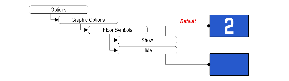
| Floor Symbols | Show / Hide | • | • | • | |||
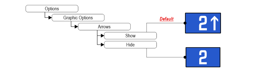
| Arrows | Show / Hide | • | • | • | |||
| Fixed Symbols Positions | No / Yes | • | • | • | |||
| Filter Blinking Signals | No / Yes | • | • | • | |||
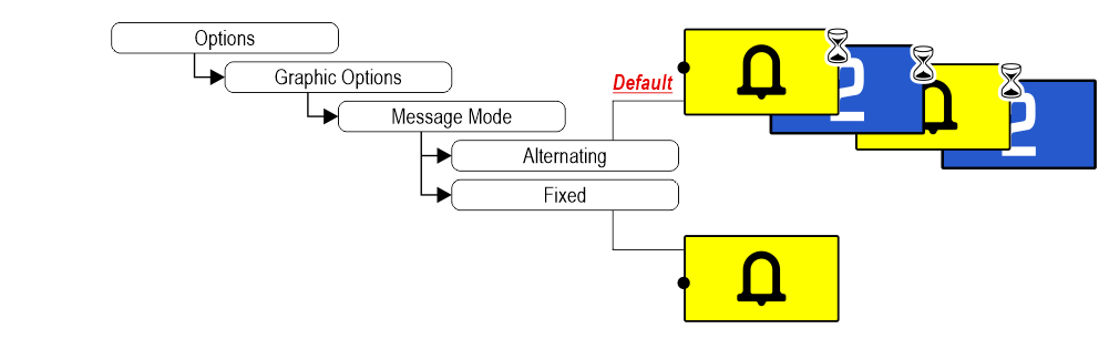
| Message Mode Orientation | Alternating / Fixed | • | • | • | |||
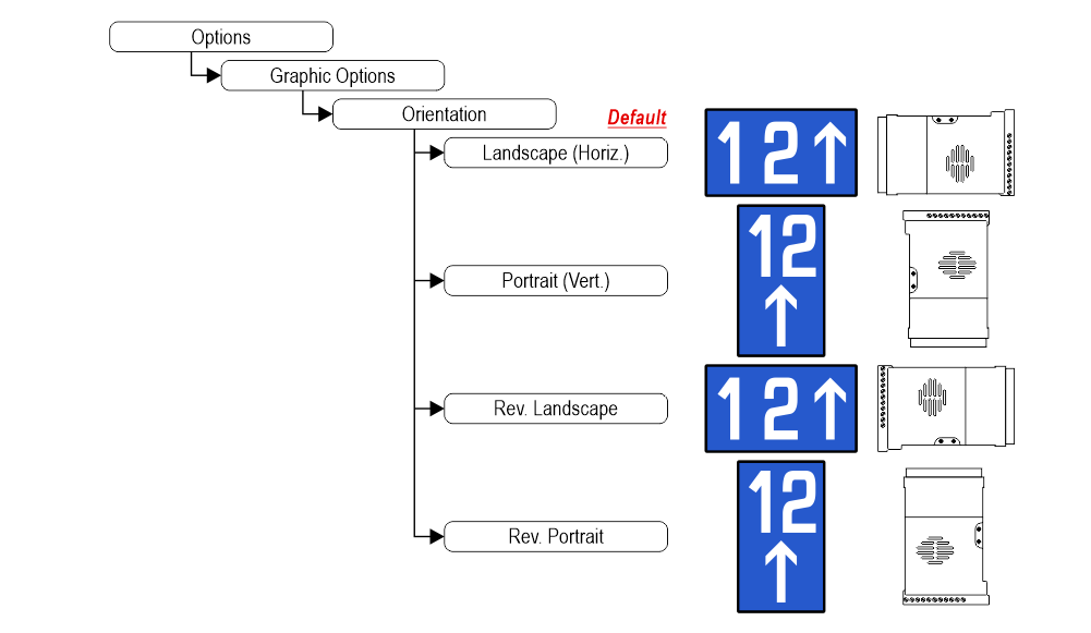
| Orientation | Landscape (Horiz.) / Portrait (Vert.) / Rev.Landscape / Rev.Portrait | • | • | • | |||
| S1-S5 inputs Configurations | Input S1 / ... / S5 | • | • | • | |||
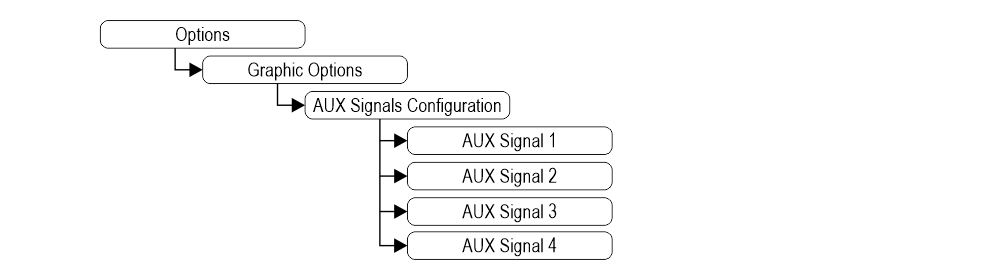
| AUX Signals Configurations | AUX Signal 1 / 2 / 3 / 4 | • | • | • | |||
Adjusting audio level
Set up Raffaello as elevator car indicator or floor indicator
 1) – Elevator car Position Indicator (default)
2) – Floor Position Indicator
Arrow setting up
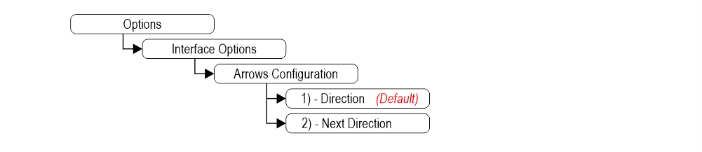 1) – Direction arrows (default)
2) – Next direction arrows (instructions below)
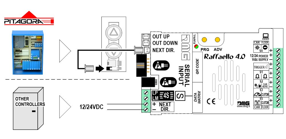
Next Direction Arrows enabled from input
Gong and arrows light up only on the position indicators with the “NEXT DIRECTION” input powered.
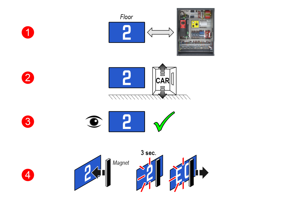
Next Direction Arrows locally programmed
Through the addressing procedure one can permanently assign to each indicator the information of the floor on which it is mounted; in this way, next direction arrows only light up at the floor where the elevator car is positioned.
– Addressing procedure
1) – Connect all position indicators to the ENCODER or PLAYBOARD controller.
2) – Position elevator car on the floor of the Display which needs to be directed.
3) – Verify that the characters/numbers/letters visualized are the desired ones.
4) – Put a magnet in front of the indicator and wait for it to blink for 3 seconds for confirmation.
5) – Repeat procedure for each floor.
 If the DEUM Encoder is used, please refer to the relevant manual
Enable “Car at Floor” signal from “NEXT DIR.” input
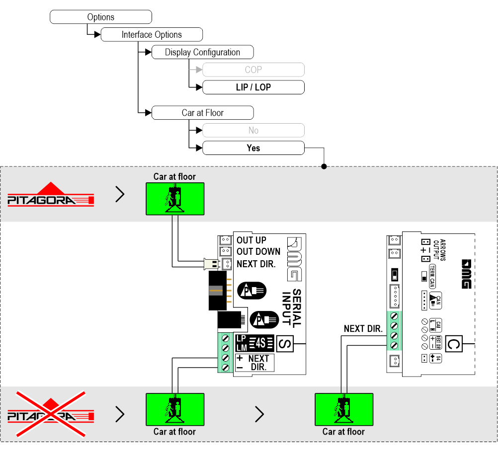
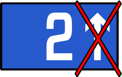
Set up the gong to be independent from arrows
Set up CAN BUS protocol transmission speed
Intermediate floors visualization
Set up floors OFFSET
Set up first visualization
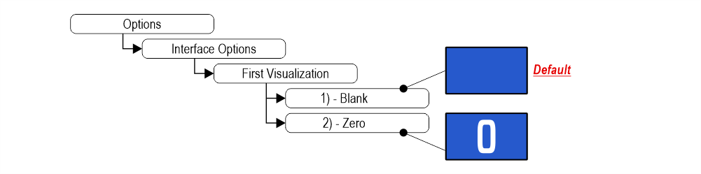 1) – It does not display any numbers
2) – Lowest floor
Set up Parallel position common input
Set up scrolling arrows
2) – Scrolling arrows
Enable auxiliary signals
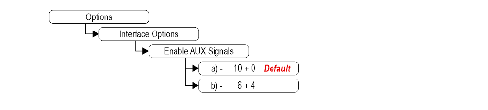 a) – 10 Floor parallel inputs (X01÷X10) + 0 AUX Signals
b) – 6 Floor parallel inputs (X01÷X06) + 4 AUX Signals (X07÷X10)
Set up the display delay of floor change
The display delay helps avoiding visualization errors during floor change.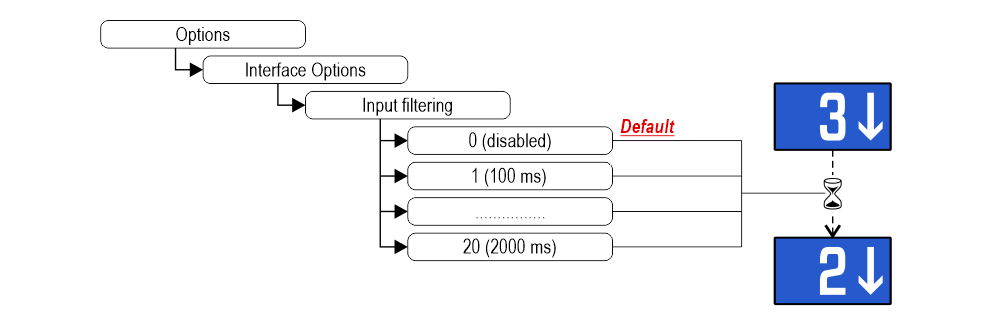
Enable Gong from arrow input
The gong command is handled simultaneously with the arrows without connecting the “trigger” terminals.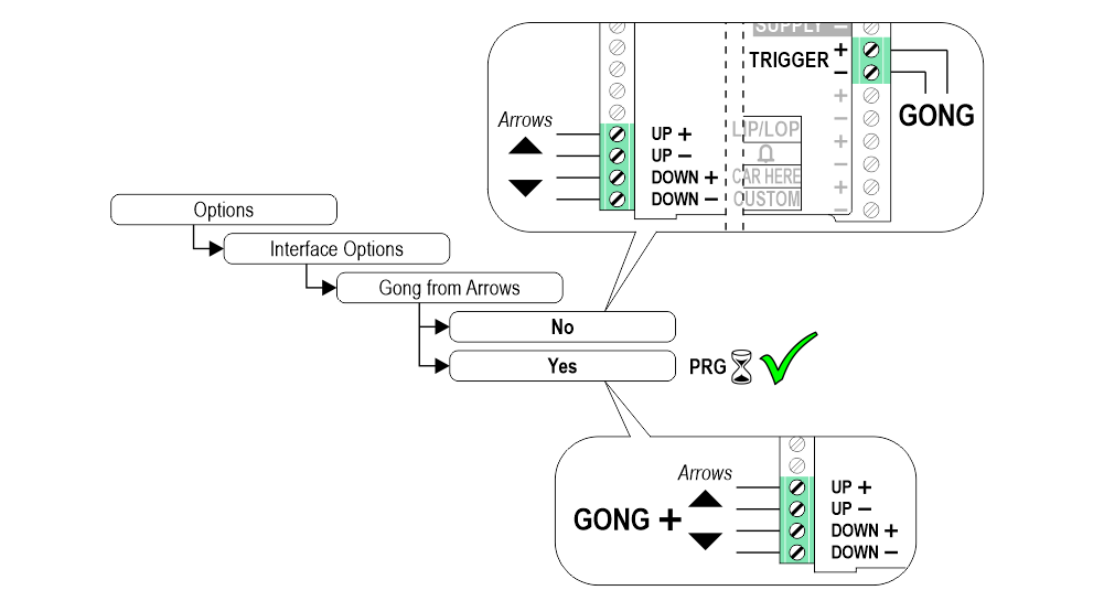
Associate the floor position indicator with the duplex controllers
The parameter allows to assign the display (floor) to a unique controller. The Duplex-Light typology includes 2 controllers with a single BDU line and a maximum of 2 displays at the main floor.
This parameter can only be set with the CAN protocol on the Pitagora 4.0 system.
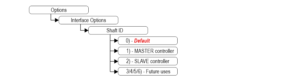
0) – To be associated with the lift car position indicator.
1) – The display will show the information of the MASTER controller.
2) – The display will show the information of the SLAVE controller.
3/4/5/6) – Future uses.
This parameter can only be set with the CAN protocol on the Pitagora 4.0 system.
0) – To be associated with the lift car position indicator.
1) – The display will show the information of the MASTER controller.
2) – The display will show the information of the SLAVE controller.
3/4/5/6) – Future uses.
Enable energy saving function
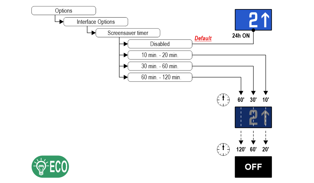 “Energy saving” mode to reduce consumption when idle.
Set up Font
Set up flat Style Color
Set up gradient Style Color
Show/Hide position
Show/Hide arrows
Set up Symbols position
Landscape orientation modes only.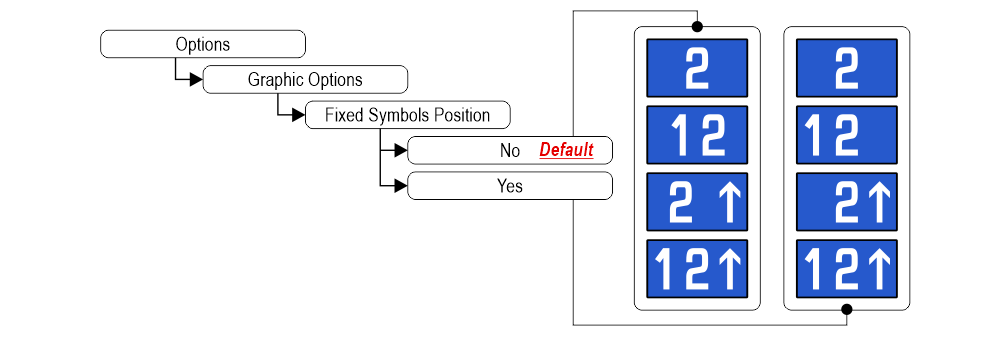 If “Yes”, the symbols will stay in fixed positions independently of the arrow status.
If “Yes”, the symbols will stay in fixed positions independently of the arrow status.Signalizations (visualization)
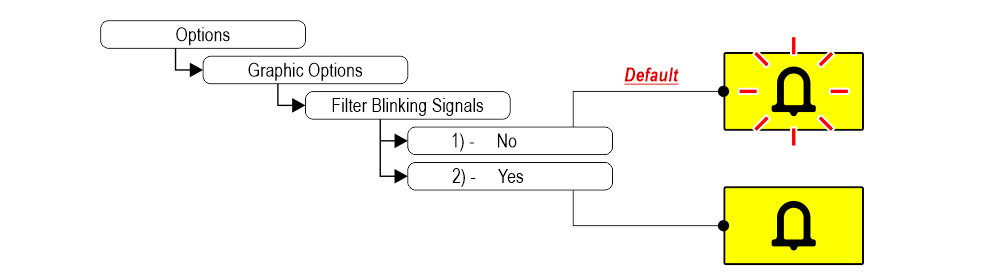 1) – Fixed or blinking signalizations (input from controller).
2) – Fixed signalizations.
Setting the signalization viewing mode
Set up Display orientation
Set up service message inputs
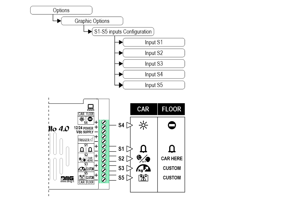
Set up auxiliary signal
Restore the factory settings

Customizations of floor
1) Car at floor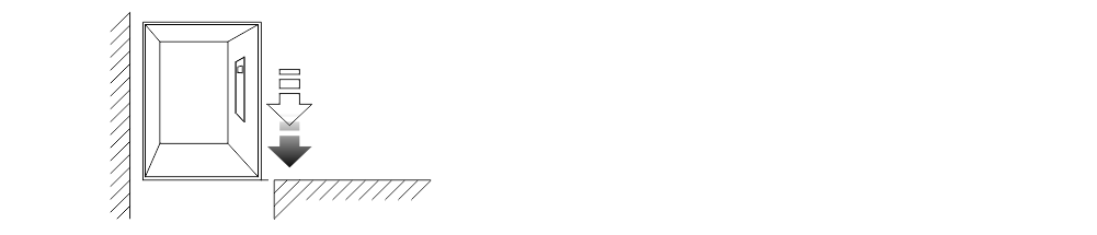
2) Set up Floor Numbers / Letters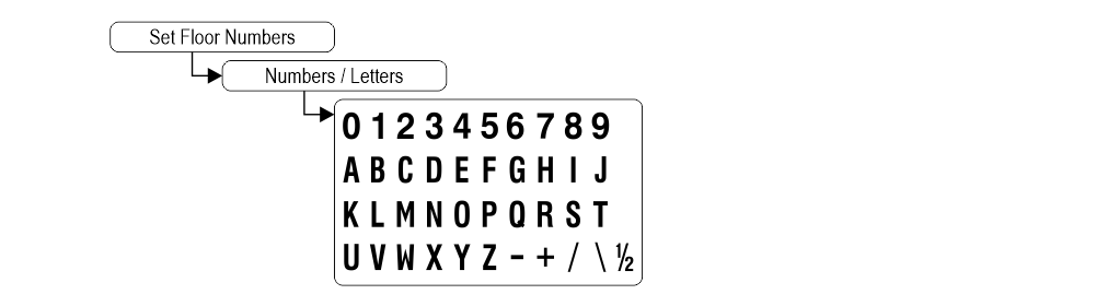
2) Set up Floor Numbers / Letters
Software Raffaello CODER
You can manage the lift data of the Raffaello display using the Raffaello CODER software (ask your sales referent).
Below a short guide.
Datasheet
Raffaello 4,3″
| Dimensions | 132x80xh20 mm 138x100xh26 mm (EN 81-71) |
| Screen (Viewable area) | 95×74 mm / 480×272 pixel • 65.000 colors |
| Power supply (position input) | 12÷24V DC ±10% |
| Absorption | DISPLAY 12V DC: Max 102mA • 24V DC: Max 71mA PANIC LIGHT 12V DC: Max 93mA • 24V DC: Max 50mA |
| Indicators inputs | S1 / S2 / S3: 12÷24V DC ±10% (opto-isolated) Impedance = 3Kohm |
| Operating temperature | -10°C ÷ +50°C |
Raffaello 5″
| Dimensions | 125x96xh23 mm |
| Screen (Viewable area) | 111×63 mm / 480×272 pixel • 65.000 colors |
| Power supply (position input) | 12÷24V DC ±10% |
| Absorption | DISPLAY 12V DC: Max 103mA • 24V DC: Max 72mA PANIC LIGHT 12V DC: Max 90mA • 24V DC: Max 50mA |
| Indicators inputs | S1 / S2 / S3: 12÷24V DC ±10% (opto-isolated) Impedance = 3Kohm |
| Operating temperature | -10°C ÷ +50°C |
Video Tutorial
The graphics parameters configuration
Offset value
The common programming
Firmware

Troubleshooting
| Fault description | Raffaello 4,3" / 5" | |
|---|---|---|
| Installation errors | The display does not light up | Check for the presence of 12/24VdC voltage. |
| Make sure that the type of voltage complies with that required (direct voltage, not alternating, not rectified). | ||
| Check the correct polarity on the power terminals. | ||
| Even if the display seems off, check that the red FAIL led on the back is not on, if it is, in this case the problem would be of a different nature. Please contact DMG. | ||
| Press the PRG key and make sure that the menu does not appear. In this case the screen is black but without input it could give the idea of being turned off. | ||
| Steady red LED | Device in FAIL. Indicates a Serious system ERROR, inherent in a hardware defect or other unresolvable defect. Please contact DMG. | |
| Flashing red LED | Device in FAIL. Indicates a generic system ERROR, in this case there may have been a problem relating to the graphic or fw programming of the device, an update via USB may be sufficient. Ex: the display shows "NO GRAPHIC FOUND" associated with the flashing red LED (see error messages). | |
| The display does not show numbers and/or arrows | Make sure that the type and voltage value comply with those required for the inputs, make sure you have correctly set the type of common. | |
| Long presses of the PRG key are not detected by the display. | Update the display to the latest firmware version. | |
| Error messages | BLOCKED DEVICE INSERT CODE | If this message appears when you turn on the device, it means that it was not unlocked by mistake during production. Please contact DMG. |
| Wrong recognition Coding interface | For displays that use coding interfaces (slots), the data of the inserted interface is shown on the screen at startup. If an inconsistency occurs, the defect is to be attributed to the HW. | |
| The display shows the indication "E" followed by a number X | In this case, it is a generic error indication due to an incorrect setting of the display. Please contact DMG | |
| Display defects | The display shows vertical lines | If the lines are fixed and black, please contact DMG. |
| The display shows horizontal lines | ||
| The display is white | Please contact DMG. | |
| The display has inverted colors or with a "negative" effect | Please contact DMG. | |
Download
| Reference | Version | Link |
|---|---|---|
| 1.0 (current version) | Download PDF (English) | |