(v 2.3)
Safety and usage cautions
Before installing our products, we recommend you to consult the section about safety and usage cautions at the link below

Main features
- 2 relays thresholds + analog output
- Automatic compensation of elevator car dynamic load during travel (load locking input)
- Automatic compensation of elevator car static load
- Adjustable compensation of travelling cable weight
- Detachable programming tool (2×8 characters)
- External cover water protection (IPX2)
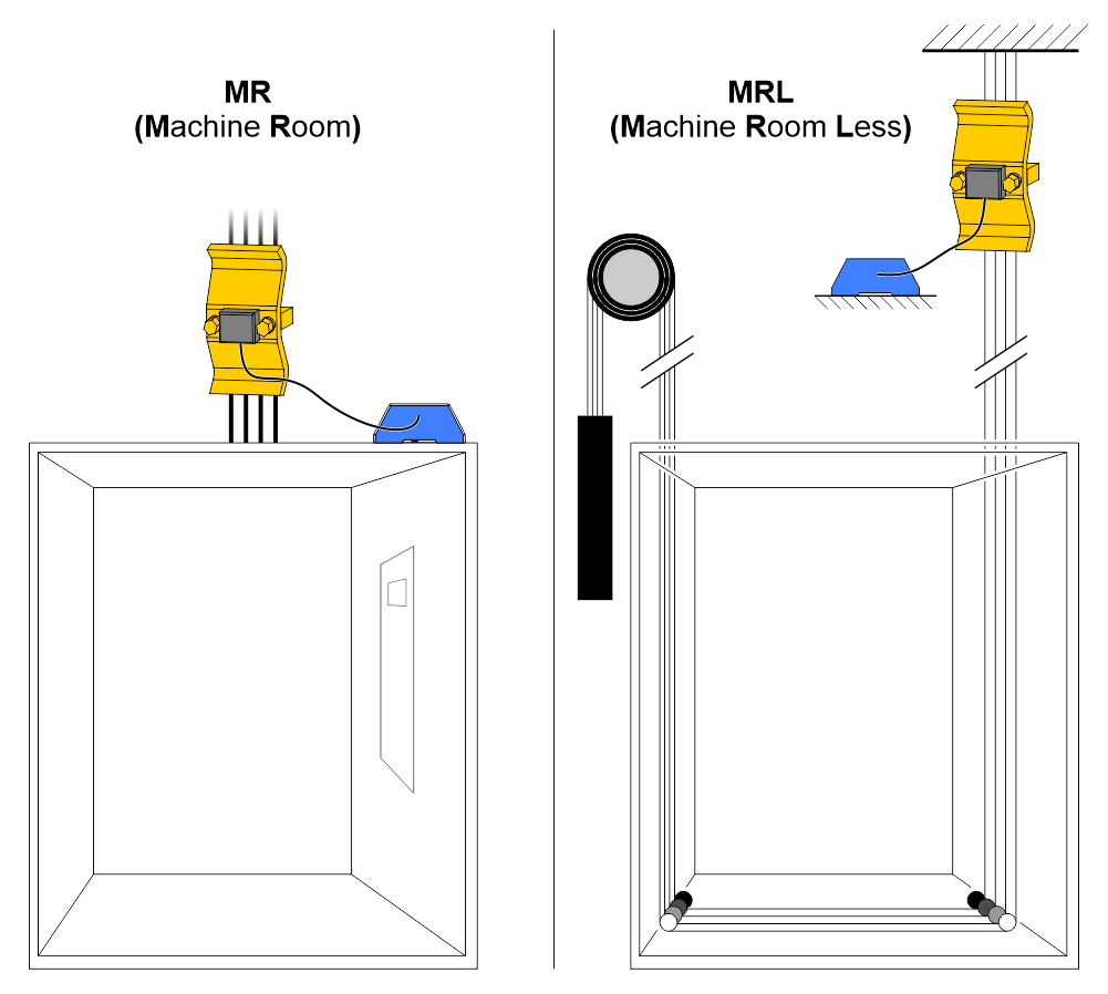
System components
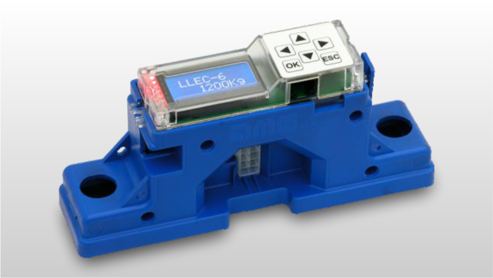
LLEC6 with integrated sensor
A) – code [EWSLL6FRM] – LLEC6 with integrated sensor (for car frame)
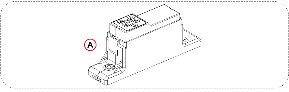
LLEC6 for external sensors
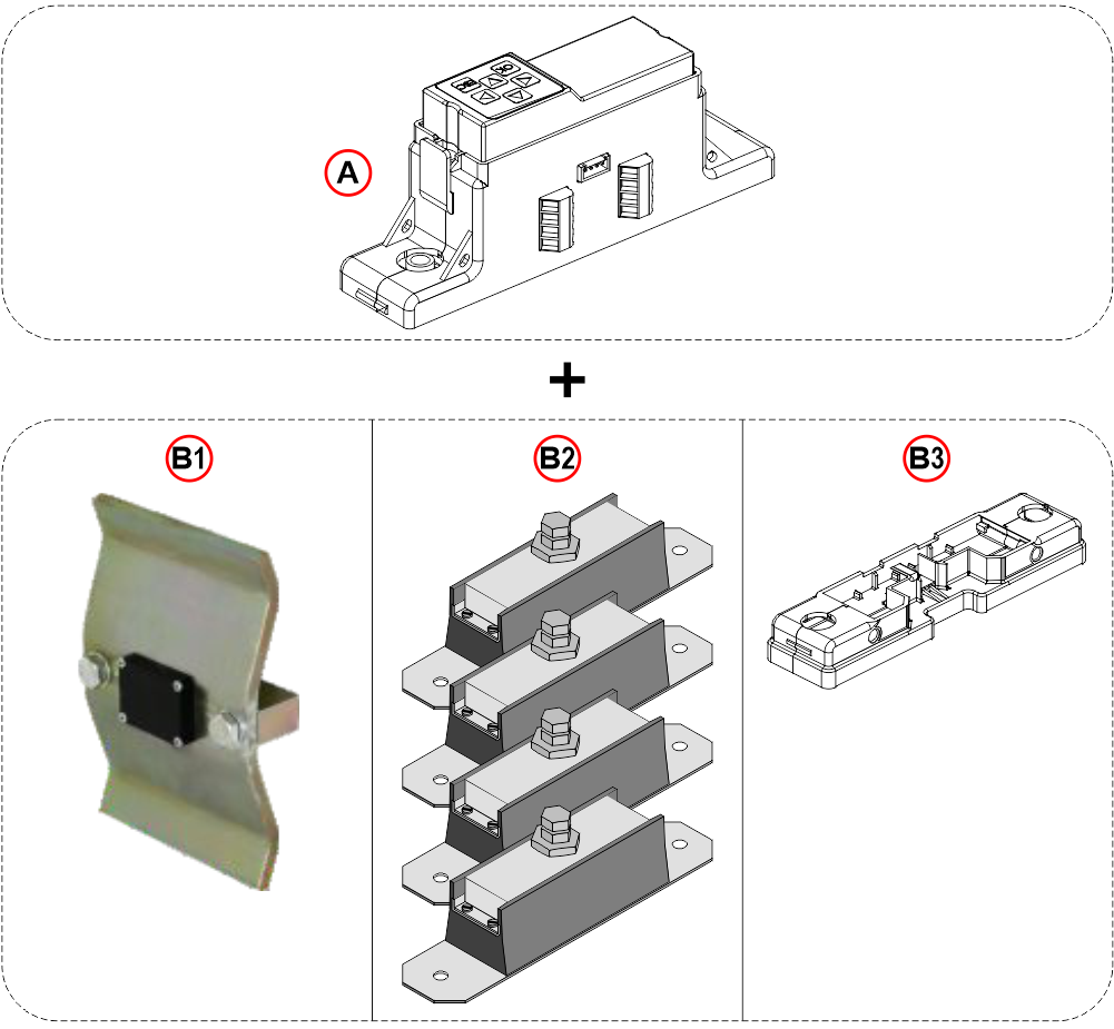
A) – code [EWSLL6ROP] – LLEC6 for external sensors
B1) – External sensor for ropes (2mt cable)
code [EWS.RS6X13] – Maximum 6 ropes (Ø 13mm)
code [EWS.RS7X10] – Maximum 7 ropes (Ø 10mm)
code [EWS.RS10X8] – Maximum 10 ropes (Ø 8mm)
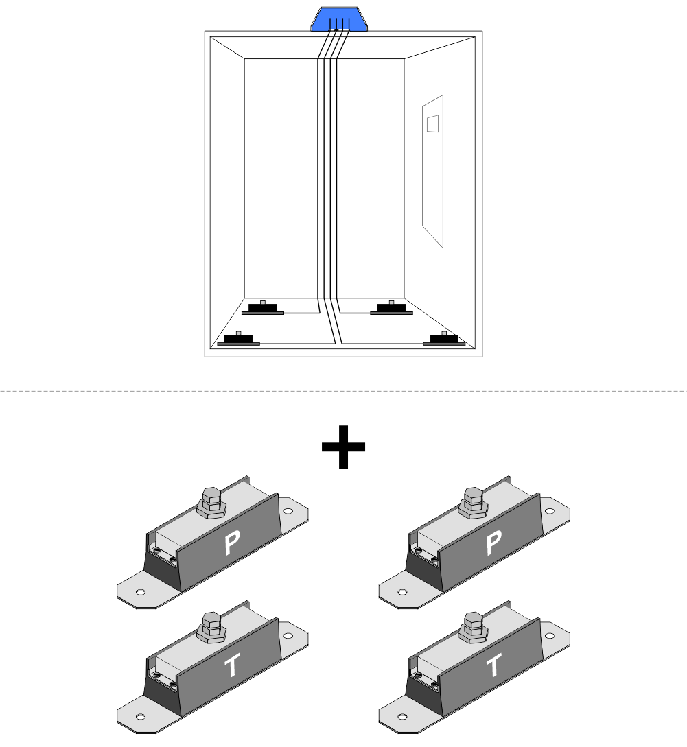
B2) – External sensors kit for elevator car bottom (6mt cable)
code [EWS.CS300] – 300 kg for each sensor
code [EWS.CS400] – 400 kg for each sensor
code [EWS.CS700] – 700 kg for each sensor
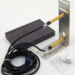
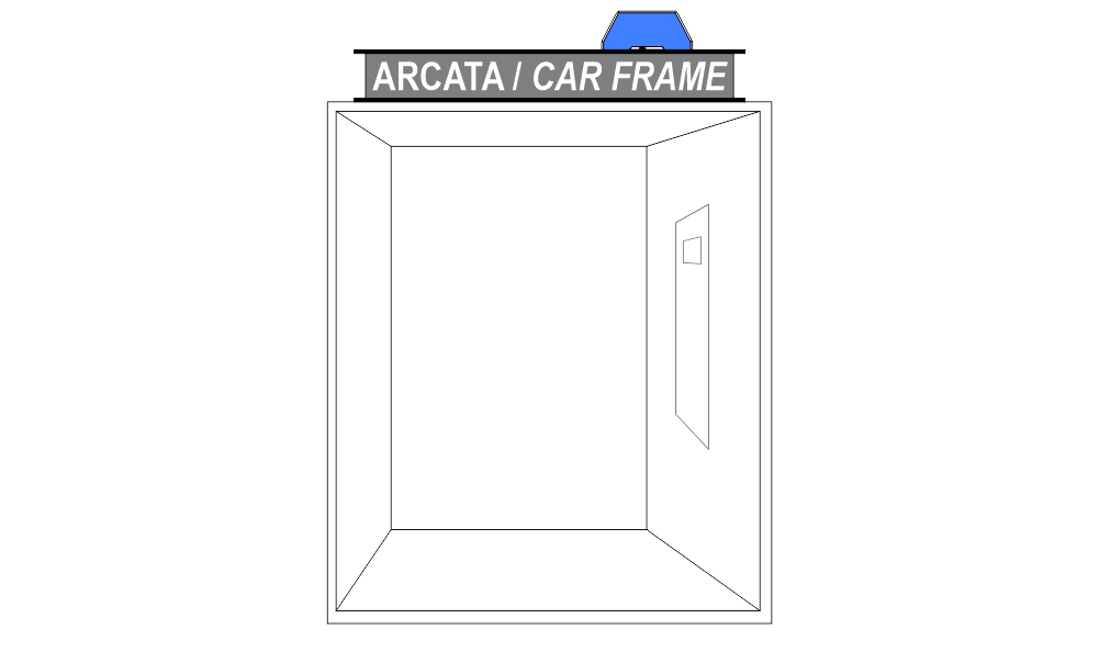
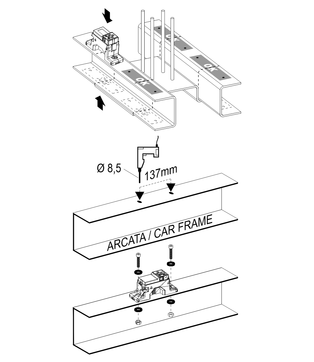
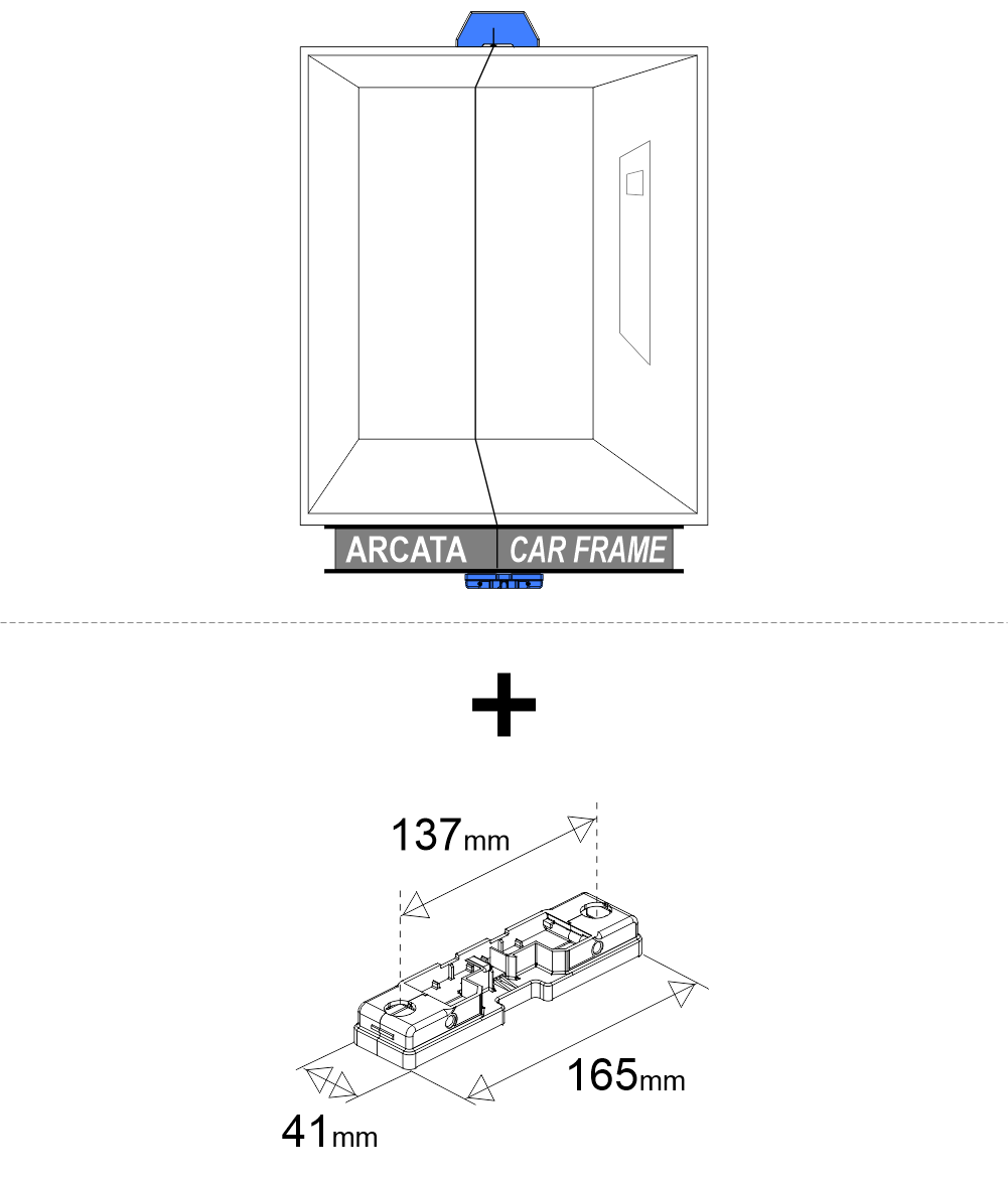
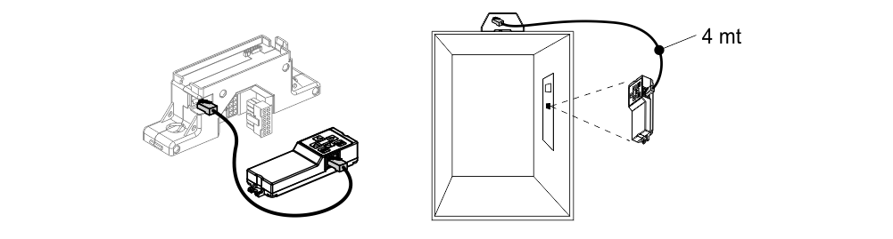
B3) – code [EWS.CSSLI] – External sensor for car frame (4mt cable)
Optional components
 code [AUT.KIT08] – Magnetic sensors (NC)
 code [EWS.AL212] – Power unit 220V
 code [EWS.LL3S] – third threshold
Installation
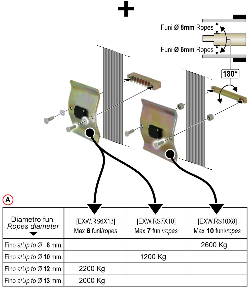
A) – Maximum load table (Mass structure + lift capacity)
In case of lift roping 2:1 (sensor on fixed-ending + pulley) maximum load is doubled.
Wiring Instructions
Control unit connections
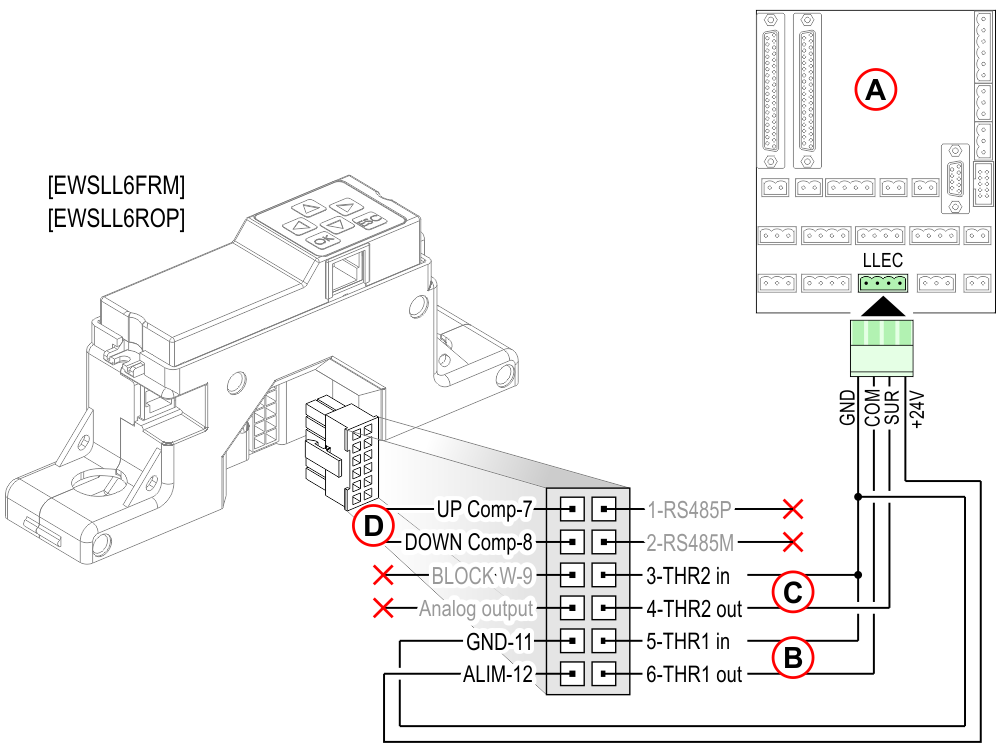
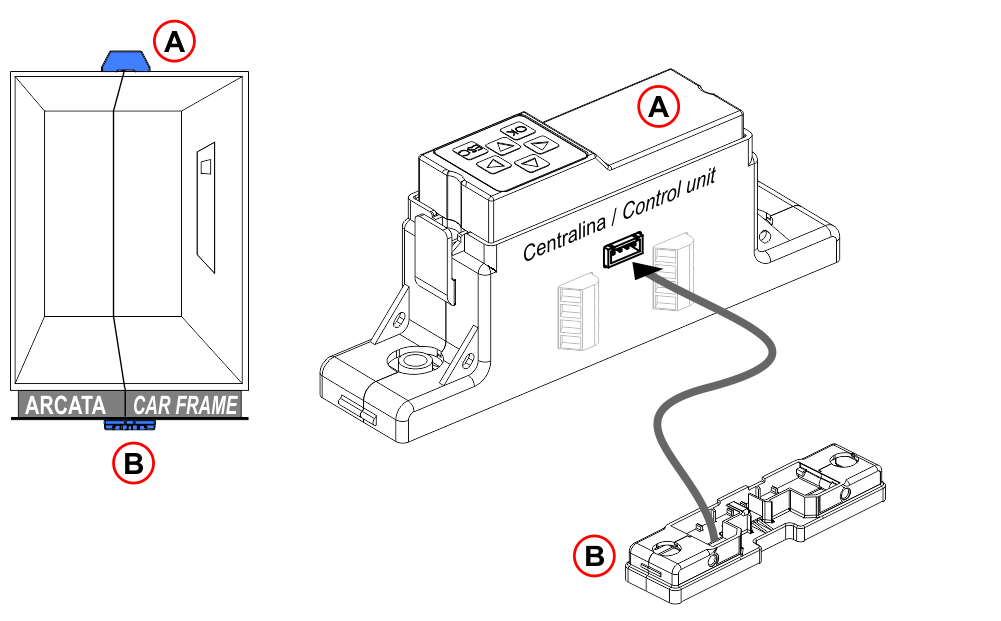
 A) – TOC box on the cabin roof
B) – Threshold 1
C) – Threshold 2
D) – Travelling cables compensation
 A) – TOC box on the cabin roof
B) – Threshold 1
C) – Threshold 2
D) – Travelling cables compensation
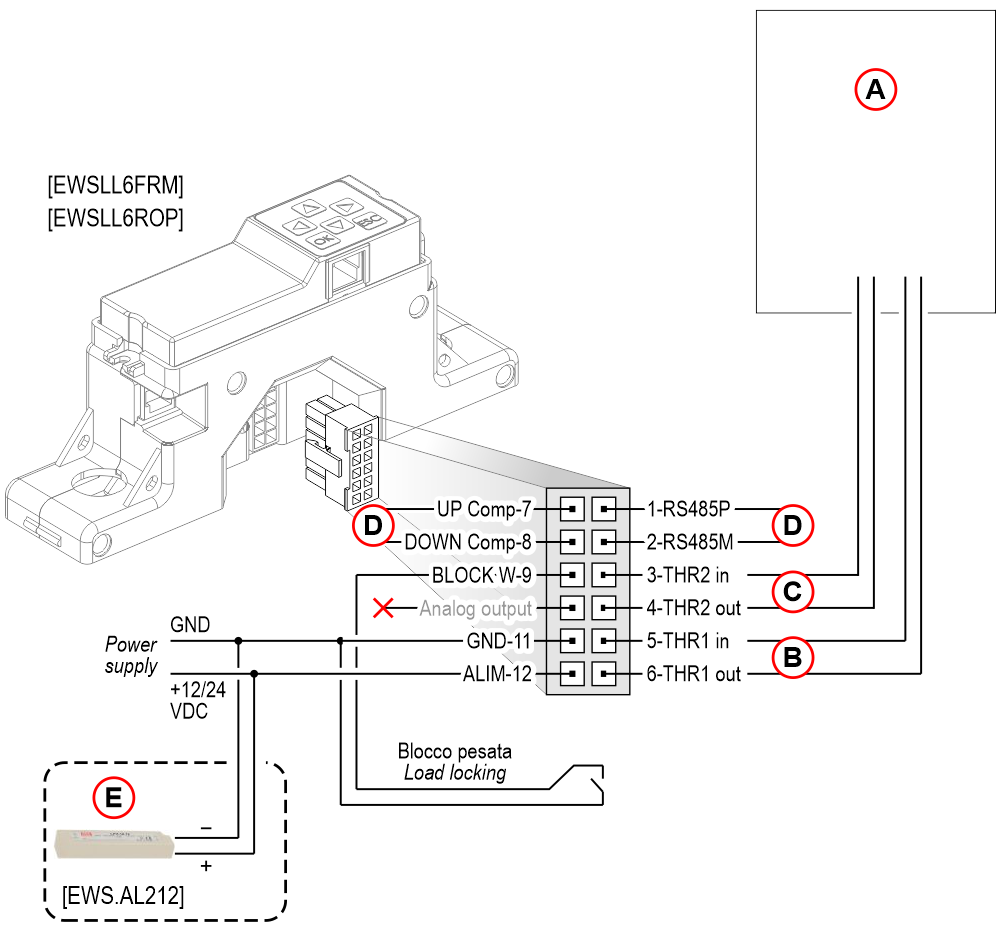 A) – Dry contact (NO/NC) of the controller
B) – Threshold 1
C) – Threshold 2
D) – Travelling cables compensation
E) – 220V external power unit
External sensors connections
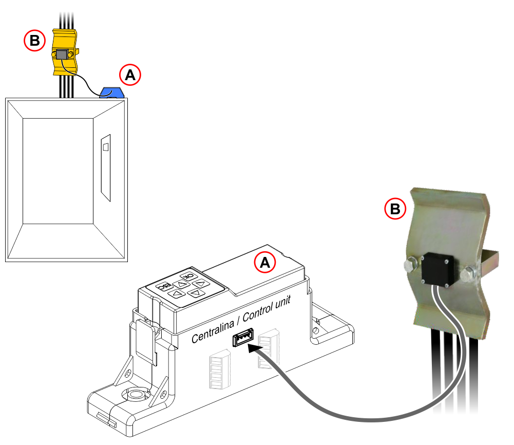
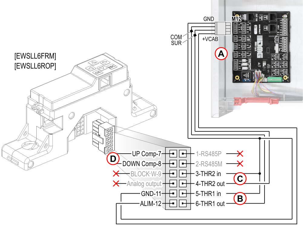
A) – Control unit
B) – Ropes’ sensor
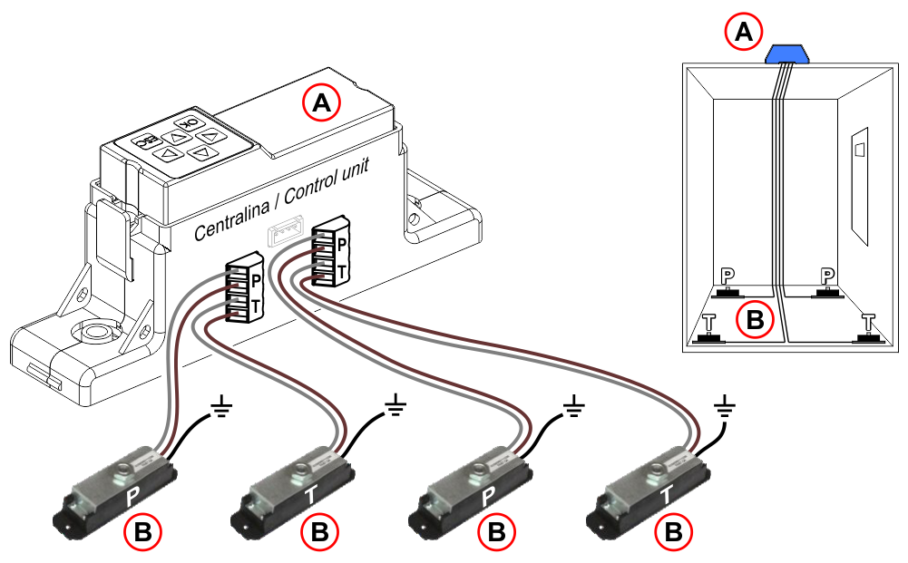
8 sensors wiring diagram
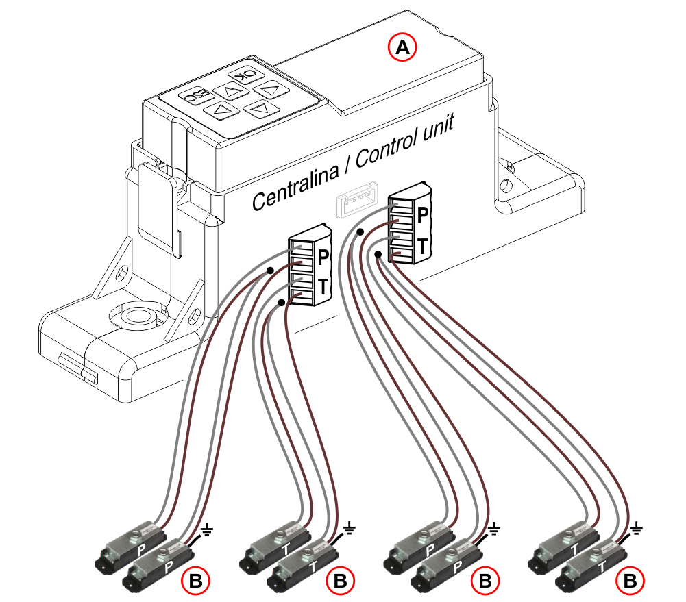
A) – Control unit
B) – Elevator car bottom sensors (P= Pression / T= Traction)
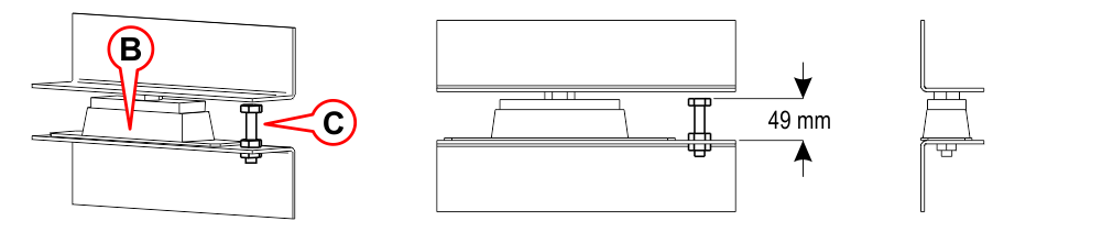 B) – Sensor
C) – Bolt M12
A) – Control unit
B) – Car frame sensor
Third threshold connection
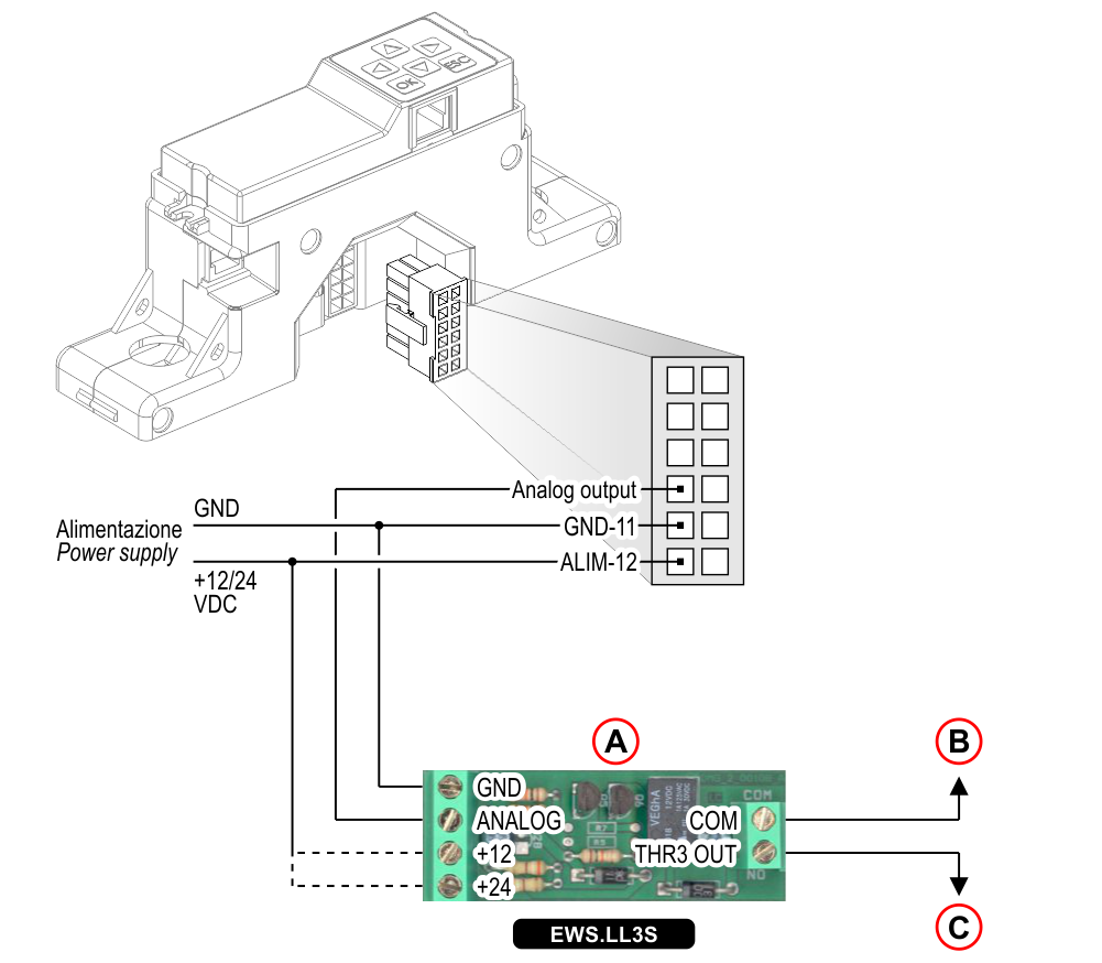
A) – Third threshold
B) – Common
C) – Third threshold output
Calibration

| 1 | ---> | [▼] | ---> | < Setting > | |
| 2 | ---> | [OK] | ---> | < Warm-up, please wait > | |
 | Sensor warm up | ||||
| < Calibration > | |||||
| 3 | ---> | [OK] | ---> | [▲] [▼] [◄] [►] | Enter the capacity of cabin (Kg) |
| 4 | ---> | [OK] | ---> | < Empty cabin, are you sure ? > |  |
| 5 | ---> | [OK] | ---> |  | 10 sec. to exit the cabin |
| < Reference weight > |  |
||||
| 6 | ---------> | [▲] [▼] [◄] [►] | Enter the weight to be loaded in the cabin for calibration (at least 30% of capacity) |
||
| 7 | ---> | [OK] | ---> | | 10 sec. to exit the cabin |
 Thresholds values are automatically set (editable from < Thresholds > menu):
Threshold 1 = 100% Capacity; contact N/O – Threshold 2 = 115% Capacity; contact N/O
Travelling cables compensation
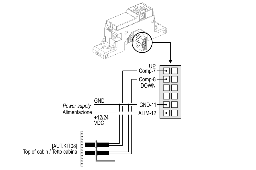
[AUT.KIT08]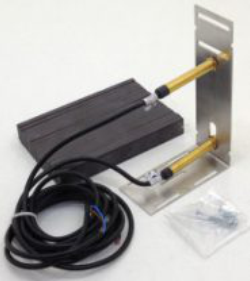
In lifts with significant cables’ overall weight, the compensation of travelling cables’ weight is an important step. One has to account for: 1) Lift max load, 2) travelling cables’ weight per meter, 3) Shaft total length.
Before performing this procedure, in addition to the main connections, [AUT.KIT08] external position sensor must be connected. If you already have DEUM15 encoder you need only connect LLEC6 control unit without using the external sensor, using the serial line for cables’compensation.
Position sensor wiring
DEUM encoder wiring
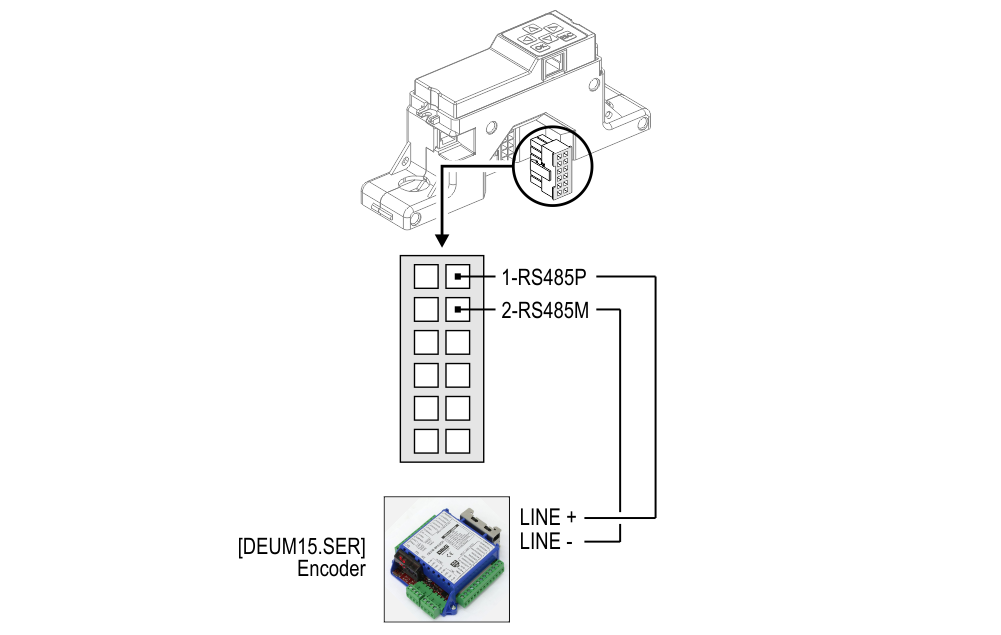
![]() DEUM15 encoder programming requires a serial position indicator.
DEUM15 encoder programming requires a serial position indicator.
Compensation procedure
![]() First, perform the system calibration
First, perform the system calibration
| 1 | ---> | [▼] | ---> | < Setting > |
|---|---|---|---|---|
| 2 | ---> | [OK] | ---> | < Calibration > |
| 3 | ---> | [▼] | ---> | < Compensation > |
| 4 | ---> | [OK] | ---> | < Bottom floor, are you sure ? > |
| 5 | ---------> | 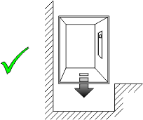 Cabin at the lowest floor Cabin at the lowest floor |
||
| 6 | ---> | [OK] | ---> | |
| 7 | ---> | [OK] | ---> | < Top floor, are you sure ? > |
| 8 | ---------> | 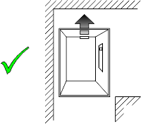 Cabin at the highest floor Cabin at the highest floor |
||
| 9 | ---> | [OK] | ---> | |
Cables weight is automatically set (editable from < Configuration > / < Compensation > menu). Set the value to 0 kg to disable the function.
Advanced programming
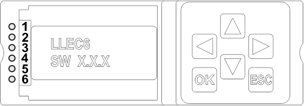
Programming tool
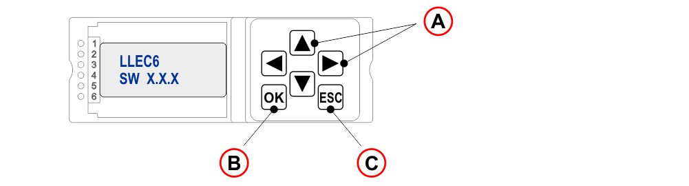
A) – Browse options at current level.
B) – Access to menu and confirm selection.
C) – Exit from current level and return to previous level.
| Menu | Options | Note | |
|---|---|---|---|
| Menu language Italiano / English / Française / Deutsch / Español / Portugués / Russkiy | |||
| [▼] | |||
| Setting | [OK] | Calibration | System calibration |
| Compensation | Travelling cables compensation | ||
| [▼] | |||
| Threshold | [OK] | Threshold 1 Threshold 2 Threshold 3 (optional) | Threshold 3 0 = Off • Min. 15 Kg. • NO/NC |
| [▼] | |||
| Configuration | [OK] | Compensation | You can manually change the parameters measured in the calibration and compensation procedure (included threshold NO or NC contact) |
The programming tool can also be separated from the control unit and connected by telephone cable. (ex.: back of the pushbutton panel)
Troubleshooting
| Problem | Solution |
|---|---|
| The device is switched off (LED 1 OFF). | Power up the device. |
| The device doesn't work (LED 2 does NOT flashing). | Power cycle the device. |
| Thresholds exceeded and active (LED 3/4 ON). | Reduce the car load to reset thresholds.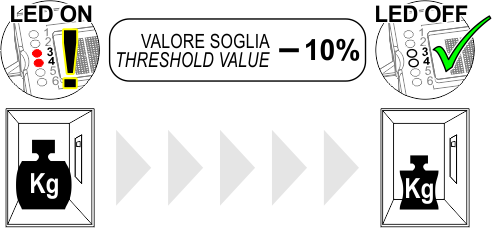 |
![]() While replacing a LLEC2/3, the existing 120 Ω sensors can be maintained only by powering the LLEC6’s 12V control unit via the EWS.AL212 external power supply.
While replacing a LLEC2/3, the existing 120 Ω sensors can be maintained only by powering the LLEC6’s 12V control unit via the EWS.AL212 external power supply.
Diagnostic
 | Led OFF |  | Led ON (NOT Flashing) |  | Led ON (Flashing) |
| Led | Status | Led | Status | |
|---|---|---|---|---|
| Led 1 = Power supply | |  | | See "Troubleshooting" |
| Led 2 = Watchdog (Normal operating) | | | | See "Troubleshooting" |
| Led 3/4 = Thresholds 1/2 | | | | See "Troubleshooting" |
| Led 5 = Load locking | | Measuring NOT in progress | | Measuring in progress |
| Led 6 = Cable weight compensation | | Enabled | | Disabled |
Datasheet
| Dimensions | 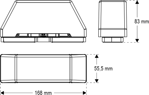 |
| Voltage | 12/24V DC |
| Max absorption | 200 mA |
| Relays output 1/2 | 1A, 30V DC (Resistive load) |
| Analog output | 0-5V, referred to GND. (5V = 100% of load) |
| Load locking input | Dry contact |
| Operating temperature | -10°c ÷ +50°c |
Download
| Reference | Version | Link |
|---|---|---|
| 2.3 (current version) | Download PDF (English) | |