(v 1.8)

Safety and usage cautions
Before installing our products, we recommend you to consult the section about safety and usage cautions at the link below

Operating Principle
Standard voice connection
Used as GSM module for emergency telephones
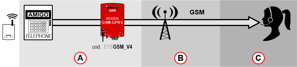
A) – Devices needed
B) – Connectivity
C) – Communication via
Wiring Instructions
Used as GSM module for emergency telephones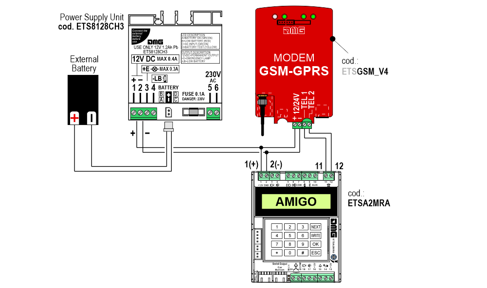
Usage
 To enable any function you need to first check whether the SIM card requires a
PIN and, if so, configure the corresponding parameter (“SIM card PIN number”).
Used as GSM module for emergency telephones
The Modem unit emulates an analogic telephone line to the connected device. The emulation includes line tone, busy line tone, ring tone, tone-dialing, DTMF forwarding.
– No programming necessary
Used to operate the Playboard controller from remote
Remote connections can be managed through DMG’s E-Cloud Software and they allow to operate our Playboard controllers and the modem units from remote. The connection occurs through the Internet with direct connection to the modem IP address.
Mandatory programming parameters
– Internet APN
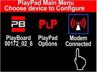
Programming
You can programm the “Telemaco” unit directly onsite with the “PlayPad” programming
module.
Programming with PLAYPAD

A) – Setting up of menu language.
B) – Setting up of modem parameters.
Menu map for programming
| Menu selection | Available choices | Description |  (*1) (*1) |  (*2) (*2) |
|---|---|---|---|---|
| Language | English / Italian / German / Russian / French / Portuguese / Dutch | Language used in notifications by the modem. | ||
| Internet APN (*3) | __________ | APN Server address (Access Point Network). |  |  |
| SIM card pin number (*4) | ____ | PIN number of the SIM card. | | |
| Geolocation | ____ | Country code required to connect to closest Fusion node. | | |
(*1) Used as GSM module for emergency telephones.
(*2) Used to operate the Playboard controller from remote.
(*3) This parameter is specific from your mobile operator.
(*4) If the SIM requires a Pin, the Modem unit will try to use the registered Pin. If there’s no Pin registered or it’s wrong, the Modem will stop its starting procedure and field people intervention will be required.
Diagnostic and Troubleshooting
Count the number of Led flashes to know the status of the installation.
Led Fault (red)
![]()
| Led Status | Description | Remedy |
|---|---|---|
 OFF OFF | No faults. | |
 1X 1X | SIM card not inserted or not recognized. | 1) Insert the card; after, switch the unit off and then on again. 2) Try the card in another unit (ex. a mobile phone). |
| 2X | SIM card requires a Pin or the registered Pin is not valid. | 1) Enter PIN number using a mobile phone. 2) Register the PIN number in the Modem unit using a PlayPad or the application “DMG Modem Programmer”. 3) Check if the registered PIN is correct. |
| 3X | Network fault. No mobile network available. | 1) Check that the antenna is correctly connected. 2) Check the presence of GSM signal where the unit is installed. |
| 4X | GPRS data connection not possibile through mobile network. | 1) Check the presence of GPRS signal where the unit is installed. 2) Check if the APN parameter (Access Point Network) is correct. 3) Check that the SIM card and its contract include a data connection bundle. |
| 5X | Data connection rejected by the operator. | 1) Check the SIM credit. 2) Check that the SIM card and its contract include a data connection bundle. |
| 6X | Configuration fault. | 1) If the data connection is active, namely an APN is configured and the “reporting mode” parameter is set on Mail or the SMS option is enabled, then check that Server SMTP, SMTP Server Port and at least one of 5 recipients are configured. 2) If the “ reporting mode” parameter is set on SMS, check the “SMS recipient number”. |
Led Network Status (green)
![]()
| Led Status | Description | Remedy |
|---|---|---|
| OFF | Connection to network impossible. | 1) Check that the antenna is correctly connected. 2) Check the presence of GSM signal where the unit is installed. |
 1X 1X | Only GSM network available. | 1) All Voice & SMS functions are available; data connection for Email and remote connection is not possible. |
| 2X | GSM & GPRS network available. | 1) All functions are available. |
Led Signalization (green)
![]()
| Led Status | Description | Remedy |
|---|---|---|
| OFF | GSM signal too low or not detectable. | 1) Check that the antenna is correctly connected. 2) Check the presence of GSM signal where the unit is installed. |
| 1X | Weak signal. | 1) Check that the antenna is correctly connected; Voice and SMS functions are available, but data connection can be precarious. |
| 2X-5X | Good or excellent signal. | 1) All functions are available and stable. |
Led Current Operation (green)
![]()
| Led Status | Description |
|---|---|
| OFF | The modem has no operation ongoing. |
| 1X | The Modem is sending an E-Mail. |
| 2X | The Modem is sending an E-Mail on controller’s demand. |
| 3X | Incoming Voice call. |
| 4X | Outgoing Voice call. |
| 5X | Active remote connection. |
| 6X | Firmware update in progress. Don’t switch the unit off. |
Datasheet
| Dimensions (mm) |  |
| Operating power | 12/24V DC ±20% |
| Absorption | Stand by: 12V: 50mA – 24V: 25mA Voice conversation: 12V: 270mA – 24V: 100mA Data transmission: 12V: 100mA (medium), 270mA (peak) – 24V: 70mA (medium), 100mA (peak) |
| Radiofrequency | Dual Band EGSM 900 / 1800 MHz GPRS class 10 Transmission power rate: – Class 4 (2W) @ 900 MHz – Class 1 (1W) @ 1800 MHz |
| Local telephone line for the connection of an emergency phone | Line impedance: 600 Ohm Ring voltage and frequency: ~ 120 Vpp 25 Hz |
| Operating temperature | -10°C ÷ +50°C |
Download
| Reference | Version | Link |
|---|---|---|
| GPRS functionality eliminated | 1.8 (current version) | Download PDF (English) |
| 1.7 | Download PDF |