
General layout
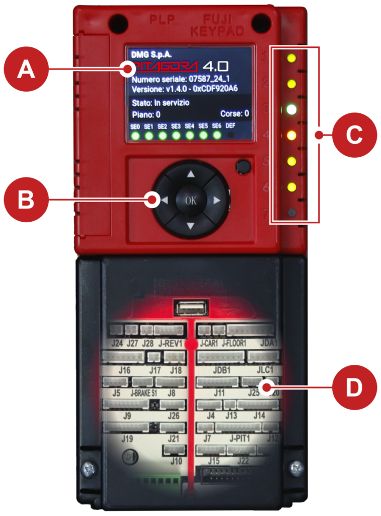
A) 2,8” graphic display for menu viewing.
B) Programming keypad with six navigation keys.
C) Diagnostic LEDs (see below for details).
D) Motherboard connections (see below for details).
To access the connectors you need to remove the protective cover.
Diagnostic LEDs description

| LED 1 | Active CAN Multiplex Termination: the LED turns off when a MULX board is connected (the termination moves to the MULX board of the first and last connected controller). | |
| LED 2 | Active Cabin CAN Termination: the LED turns off when an expansion board is connected inside the controller (the termination moves to the last expansion board). | |
| LED 3 | RGB LED: The color of this LED indicates the operating status of the system according to the table below: | |
| COLOUR | OPERATING STATUS | |
| LED off | The system is performing the reset procedure | |
| GREEN | The system is in normal operation mode | |
| YELLOW | The system is in inspection mode | |
| PINK | The system is in temporary operations mode | |
| PURPLE | The system is out of service (parking of cabin) | |
| CYAN | The system is running in priority mode (LOP / CAR) | |
| RED | The system is operating in Fire-fighters mode | |
| WHITE | The system is performing the emergency procedure | |
| BLUE | The system is performing the elevator car drift control procedure | |
| LED 4 | Yellow LED: The LED flashes to indicate the normal operation of the motherboard. | |
| LED 5 | Green LED: The lit LED indicates the status of the safety chain at point SE5. | |
| LED 6 | Green LED: The lit LED indicates the presence of the cabin in the door area. | |
| LED 7 | Red LED: The off LED indicates no active faults. If one or more faults are active, the LED flashes. If one or more blocking faults are present for the cabin, the LED is lit continuously. | |
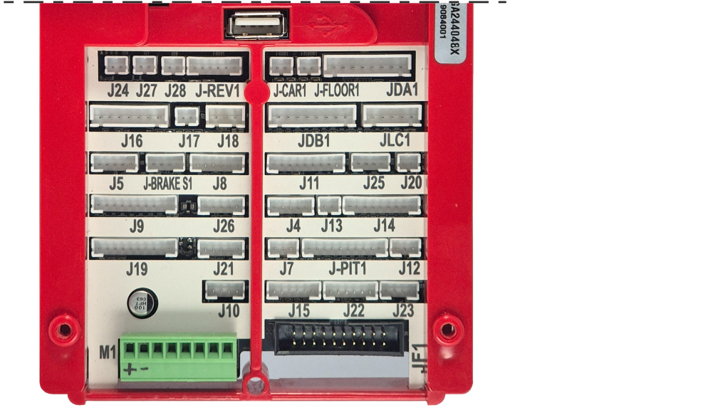
Connectors description
| Name | Description | |
|---|---|---|
| FJ1 | FUJI Interface | Connection to the FUJI interface inside the inverter. |
| J-REV1 | ||
| J-CAR1 | ||
| J-FLOOR1 | ||
| JDA1 | ||
| JDB1 | ||
| JLC1 | ||
| J-BRAKE S1 | ||
| J-PIT1 | ||
| J4 | FUJI Analog / Serial | Connection to the FUJI used in case of remote Inverter. |
| J5 | ||
| J6 | Parallel Signals | Connection to the APPO Board. It includes all parallel signals available on the terminal block inside the control panel. |
| J7 | ||
| J8 | UCM Circuit | Connection to the circuit for UCM solution. Pitagora 4.0 has own certified solutions for managing of UCM solution in lift installations. The UCM system consists of three parts: • Detector who detects an Unintended Cabine Movement. • Actuator how the braking action is implemented • Stopping Device what stops the cabin. The Stopping Device must be a certified safety device and it is the installer's responsibility to ensure the compatibility of the different elements of the UCM system. For the functional verification of the entire system and the measurement of the spaces and intervention times, specific tests are provided to be carried out at the end of the assembly (see Test and measurements) For further information on connections and parameters see UCM circuit section). A non-exhaustive list of the types of UCM systems and solutions most used are shown in the following table, where different applicable solutions are highlighted, each of which has its own dedicated interface and programming circuit. The interfacing with the listed devices is carried out according to the specifications indicated in the manuals of the relevant manufacturers. When the absolute positioning system ELGO LIMAX 33CP is provided (link), its certified UCM function is used. See the "UCM system" table below |
| J9 | Relevelling Circuit | Circuit to make Door Safety Contact Bypass for: - Pre opening and/or - Re-levelling In case of Absolute Encoder Positioning system this connector is not used. The circuit management of the re-leveling operation consists of a Safety Module and a Safety Relay. This circuit allows by-pass of the safety contacts of doors, thereby permitting movement of the cab with doors open at reduced speed in the permitted area (unlocking doors area) in the case of lowering the level of the elevator car, not precise elevator car stopping, or doors pre-opening. The ISO output closes to GND. - ISO output (safety relay contact by-pass doors) open collector Max 24V 100mA - Input CCISO (Monitor ISO safety relay) closure to GND (NC) I = 5mA - Input TISO (Monitor Safty module) closure to GND (NC) I = 5mA - S11-S12 (free contact) close when ISO1 is closed The Second enable signal for the Safety module comes directly from a second sensor (ISO2) and it must close to GND. |
| J10 | Light Curtain / >|< | Use only in completely parallel Configuration. Connection to the screw terminal of cabinet. |
| J11 | Safety Chain | Connection to the SECU Board. It includes the 7 points reading from the safety chain. The system is based on an opto insulated circuit connected to earth (Inside SEC Board): - Input SE0 <-> SE6 opto-insulated 48 Vdc Above the safety circuit, a suitably sized magnetic circuit breaker (Imax = 0,5 A) must be provided. - SE0 is the start point of Safety chain (after DIS Protection inside the controller) - SE1 controls SHAFT STOP zone and PIT Inspection Box - SE2 controls Top of elevator car STOP and TOC Inspection Box - SE3 controls Limit Switches, Safety Gear, Overspeed Governor - SE4 controls FLOOR PRELIMINARY LOCKS - SE5 controls FLOOR LOCKS - SE6 controls CAR DOORS and Pre-triggered’s contact systems If the limit switch, or Overspeed governor or Safety Gear is activated (safety chain point SE3 opens), the system is set out of service. To set it back in service you must reset the SE3 error via the programming module. Obviously the safety contact of the over run final limit switch must first be reset. |
| J12 | Multiplex CAN | Connection to the MULX Board. It includes the CAN line for Multiplex installations. For further information on connections and parameters see ANNEX I. |
| J13 | Car at Floor | Signal output from Door zone sensor for luminous signal on cabinet. |
| J14 | Hydro Command | Connection to the COIL Board. It includes the moving commands for hydro installations. It can be used also in case of Remote Inverter installations. |
| J15 | EN81-21 Circuit | Connection to the Circuit to manage the Protection in case of Installation with Reduced Space in the PIT. It includes management of Bistable circuit on doors and Protection devices (pre-triggered system or Manual Protection in the Pit). For further information on connections and parameters see ANNEX IX. |
| J16 | Encoder Position | Positioning system based on an incremental encoder: - DMG Shaft Encoder or - Motor Encoder (only for VVVF Gearless Motor Lift) In case of Absolute Encoder Positioning system this connector is not used. |
| J17 | ||
| J18 | Environment Temperature | Connection to the Environmental Temperature Sensor. To use the Environment Temperature Control function the DMG temperature sensor module (Cod. Q40.SND). This function stops the system when the temperature of the engine room drops below the minimum or increases above the maximum set threshold. |
| J19 | PME Panel | Connection to the Control Panel inside the cabinet. |
| J20 | Output Spare | Generic Output used for special functions. |
| J21 | Emergency Circuit | Circuit for complete Emergency or Evacuation with Brake opening. |
| J22 | Motor Relay | Connection to the relay for Motor Contactors (or enable signals in case of Contactorless installation). It includes also the Main Contactors’ monitor input. |
| J23 | Brake Relay | Connection to the relay for Brake Contactors (or valves in case of Hydro installation). It includes also the Brake Contactors’ monitor input. |
| J24 | ||
| J25 | Batteries Test | Connection to the CHAR Board. It includes the signals for: - Low Batteries - Phase sequence (only Hydro) - Backup mode |
| J26 | Optional Boards | DMG Optional board for: - Parallel Prewired Pushbuttons (PIT8) - 16 relays output Board (16RL): The expansion card is necessary in particular to drive parallel displays (1 Wire / Floor, 1 Wire / Segment, Gray Code, binary) as the direct outputs available - 16 Input/Output Board (16IO) |
| J27 | ||
| J28 | ||
| M1 | Power Supply | Power supply from a commercial stabilized power supplier. The negative terminal of the power circuits and the battery charger must be connected to the ground. Internal Clock power supply: Super Capacitor (autonomy of 5 days without power supply). |