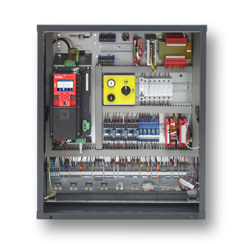
Motherboard
The control board of the Pitagora 4.0 system is based on 32-bit electronic technology and operates all types of electric and hydraulic lifts. Serial and/or parallel connections to pushbutton panels (cabin and floor) may be added. It is particularly suitable for VVVF electrical installations, also those equipped with the elevator car uncontrolled movement system (Amendment A3 or EN81-20 / 50).
– Up to 28 floors with serial control and up to 12 floors with parallel control
– CAN Bus serial line to connect display and serial Landing Operating Panels
– CAN Bus serial line for the serial elevator car communication
– APB; Down Collective, Full Collective
– Multiplex (max 6) systems control
– Alternative or selective door control on through or adjacent access systems
– Lift position control by magnetic contacts, incremental DMG shaft encoder, motor – encoder or ELGO LIMAX 33 CP Absolute Positioning System
– Programming/diagnostic Interface, on board and/or remote.
– Status diagnostic, errors, failures and I/O status
– VVVF parameters and diagnostics handling (only FUJI FRENIC LIFT LM2)
– Advanced control of VVVF with speed, comfort and precision stop control
– Software upgrading via USB Device
– RS232 serial line for PC and GPRS modem connection
– Compatibility with all DMG products
– Compatibility with all the +A3 solutions for electrical and hydraulic systems
– Protection of shaft access (Unauthorized Shaft Access)
The 4.0 motherboard contains hardware and software that allows control of the elevator and all its peripherals. Through the integrated and/or remote programming modules it allows access to all available features. Inputs and outputs are connected to all electronic and electromechanical devices in the controller and in the lift.
The Mother Board has a removable programming module that allows viewing and editing of all the basic parameters for the control panel management and configuration. In VVVF’s version, also FUJI’s parameters of the basic (menu VVVF BASE) and advanced (VVVF ADVANCED menu) configuration may be viewed and edited.
For details of the programming module operation and an extensive management system menu, see paragraph changing system parameters.
Remote programming module
An alternative way to access the configuration menu of the controller, in the view/modification mode, is by connecting the removable keypad of the DMG V3 Playboard (PlayPad), to the connector PLP V3, mounted on the Lift Control Board.
This module can be connected in various ways:
– Connected directly
– Connected by a dedicated extension cable directly on the board (in the engine room)
– Connected to the board on the elevator car roof (TOC) in the case of lifts with DMG pre-wired serial devices.
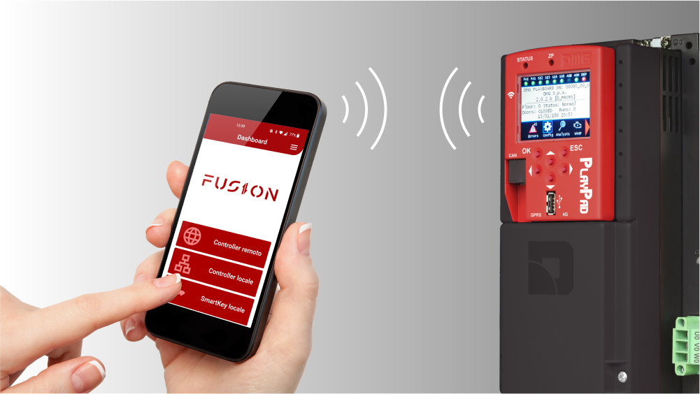
An alternative way to access the controller is based on Fusion App.
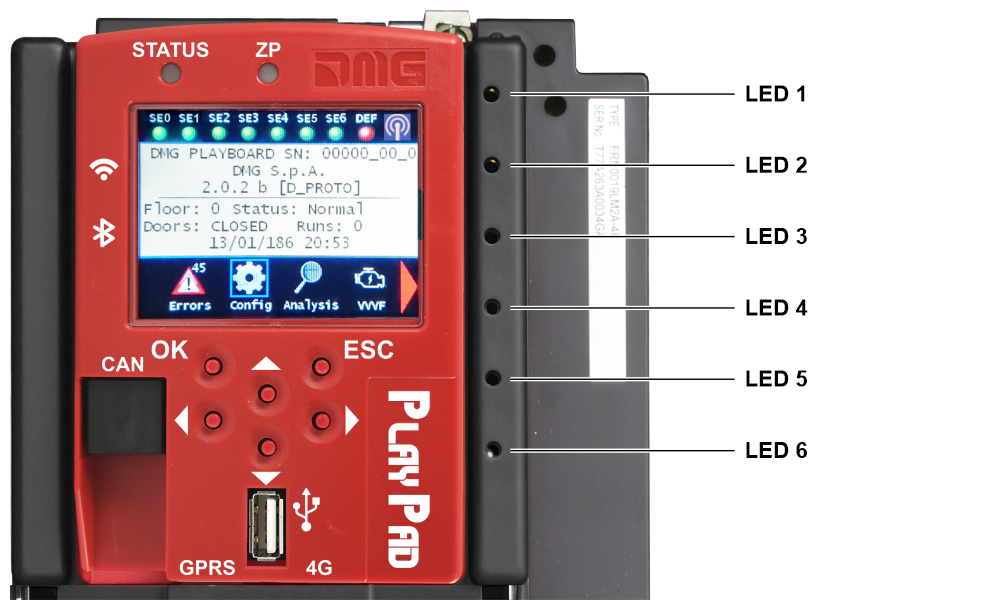
On mother board are present 6 leds for a easy diagnostic:
LED1 (Green led)
CAN Multiplex termination active: led switch off when MULX board is connected (termination automatically moves on MULX board of first and last multiplex controller).
LED2 (Green led)
CAN Cabine termination active: led switch off when an optional board (PIT8 / 16IO / 16RL) is connected inside controller (termination automatically moves on last optional board).
LED3 (RGB led)
Color of this led gives info on the internal status of lift according following table:
| Color | Status |
|---|---|
| Led off | The system is performing the reset procedure |
| Green | The system is in normal operation mode |
| Yellow | The system is in inspection mode |
| Pink | The system is in temporary operations mode |
| Purple | The system is out of service (parking of cabin) |
| Cyan | The system is running in priority mode (LOP / CAR) |
| Red | The system is operating in Fire-fighters mode |
| White | The system is performing the emergency procedure |
| Blue | The system is performing the elevator car drift control procedure |
LED4 (Yellow led)
Led blinks when board is running.
LED5 (Green led)
Led on gives the status of SE5 safety chain
LED6 (Red led)
| Led Off | No fault active |
| Led Flashing | One (or more) fault active |
| Led On | Locking fault active |
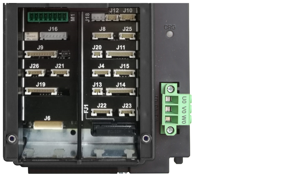
| Name | Description | |
|---|---|---|
| FJ1 | FUJI Interface | Connection to the FUJI interface inside the inverter. |
| J4 | FUJI Analog / Serial | Connection to the FUJI used in case of remote Inverter. |
| J6 | Parallel Signals | Connection to the APPO Board. It includes all parallel signals available on the terminal block inside the control panel. |
| J8 | UCM Circuit | Connection to the circuit for UCM solution. Pitagora 4.0 has own certified solutions for managing of UCM solution in lift installations. The UCM system consists of three parts: • Detector who detects an Unintended Cabine Movement. • Actuator how the braking action is implemented • Stopping Device what stops the cabin. The Stopping Device must be a certified safety device and it is the installer's responsibility to ensure the compatibility of the different elements of the UCM system. For the functional verification of the entire system and the measurement of the spaces and intervention times, specific tests are provided to be carried out at the end of the assembly (see Test and measurements) For further information on connections and parameters see UCM circuit section). A non-exhaustive list of the types of UCM systems and solutions most used are shown in the following table, where different applicable solutions are highlighted, each of which has its own dedicated interface and programming circuit. The interfacing with the listed devices is carried out according to the specifications indicated in the manuals of the relevant manufacturers. When the absolute positioning system ELGO LIMAX 33CP is provided (link), its certified UCM function is used. See the "UCM system" table below |
| J9 | Relevelling Circuit | Circuit to make Door Safety Contact Bypass for: - Pre opening and/or - Re-levelling In case of Absolute Encoder Positioning system this connector is not used. The circuit management of the re-leveling operation consists of a Safety Module and a Safety Relay. This circuit allows by-pass of the safety contacts of doors, thereby permitting movement of the cab with doors open at reduced speed in the permitted area (unlocking doors area) in the case of lowering the level of the elevator car, not precise elevator car stopping, or doors pre-opening. The ISO output closes to GND. - ISO output (safety relay contact by-pass doors) open collector Max 24V 100mA - Input CCISO (Monitor ISO safety relay) closure to GND (NC) I = 5mA - Input TISO (Monitor Safty module) closure to GND (NC) I = 5mA - S11-S12 (free contact) close when ISO1 is closed The Second enable signal for the Safety module comes directly from a second sensor (ISO2) and it must close to GND. |
| J10 | Light Curtain / >|< | Use only in completely parallel Configuration. Connection to the screw terminal of cabinet. |
| J11 | Safety Chain | Connection to the SECU Board. It includes the 7 points reading from the safety chain. The system is based on an opto insulated circuit connected to earth (Inside SEC Board): - Input SE0 <-> SE6 opto-insulated 48 Vdc Above the safety circuit, a suitably sized magnetic circuit breaker (Imax = 0,5 A) must be provided. - SE0 is the start point of Safety chain (after DIS Protection inside the controller) - SE1 controls SHAFT STOP zone and PIT Inspection Box - SE2 controls Top of elevator car STOP and TOC Inspection Box - SE3 controls Limit Switches, Safety Gear, Overspeed Governor - SE4 controls FLOOR PRELIMINARY LOCKS - SE5 controls FLOOR LOCKS - SE6 controls CAR DOORS and Pre-triggered’s contact systems If the limit switch, or Overspeed governor or Safety Gear is activated (safety chain point SE3 opens), the system is set out of service. To set it back in service you must reset the SE3 error via the programming module. Obviously the safety contact of the over run final limit switch must first be reset. |
| J12 | Multiplex CAN | Connection to the MULX Board. It includes the CAN line for Multiplex installations. For further information on connections and parameters see ANNEX I. |
| J13 | Car at Floor | Signal output from Door zone sensor for luminous signal on cabinet. |
| J14 | Hydro Command | Connection to the COIL Board. It includes the moving commands for hydro installations. It can be used also in case of Remote Inverter installations. |
| J15 | EN81-21 Circuit | Connection to the Circuit to manage the Protection in case of Installation with Reduced Space in the PIT. It includes management of Bistable circuit on doors and Protection devices (pre-triggered system or Manual Protection in the Pit). For further information on connections and parameters see ANNEX IX. |
| J16 | Encoder Position | Positioning system based on an incremental encoder: - DMG Shaft Encoder or - Motor Encoder (only for VVVF Gearless Motor Lift) In case of Absolute Encoder Positioning system this connector is not used. |
| J18 | Environment Temperature | Connection to the Environmental Temperature Sensor. To use the Environment Temperature Control function the DMG temperature sensor module (Cod. Q40.SND). This function stops the system when the temperature of the engine room drops below the minimum or increases above the maximum set threshold. |
| J19 | PME Panel | Connection to the Control Panel inside the cabinet. |
| J20 | Output Spare | Generic Output used for special functions. |
| J21 | Emergency Circuit | Circuit for complete Emergency or Evacuation with Brake opening. |
| J22 | Motor Relay | Connection to the relay for Motor Contactors (or enable signals in case of Contactorless installation). It includes also the Main Contactors’ monitor input. |
| J23 | Brake Relay | Connection to the relay for Brake Contactors (or valves in case of Hydro installation). It includes also the Brake Contactors’ monitor input. |
| J25 | Batteries Test | Connection to the CHAR Board. It includes the signals for: - Low Batteries - Phase sequence (only Hydro) - Backup mode |
| J26 | Optional Boards | DMG Optional board for: - Parallel Prewired Pushbuttons (PIT8) - 16 relays output Board (16RL): The expansion card is necessary in particular to drive parallel displays (1 Wire / Floor, 1 Wire / Segment, Gray Code, binary) as the direct outputs available - 16 Input/Output Board (16IO) |
| M1 | Power Supply | Power supply from a commercial stabilized power supplier. The negative terminal of the power circuits and the battery charger must be connected to the ground. Internal Clock power supply: Super Capacitor (autonomy of 5 days without power supply). |
| UCM system | |||
|---|---|---|---|
| System type | Detector | Actuator | Stopping device |
| Electric lift. No maneuvers with open doors. | No required. (only brakes' monitor) | ||
| Electric lift. Maneuvers with open doors. | Pitagora 4.0 | Brake controls interruption (safety chain open) | Brakes (*) |
| Electric lift. Maneuvers with open doors with ELGO LIMAX 33CP | ELGO LIMAX 33CP | Brake controls interruption (safety chain open) | Brakes (*) |
| Electric lift. Over Speed Governor with anti drift device (**) | Pitagora 4.0 | Power interruption of the pin. | Safety gear |
| Electric lift. Over Speed Governor with anti drift device (**) with ELGO LIMAX 33CP | ELGO LIMAX 33CP | Power interruption of the pin. | Safety gear |
| Hydraulic lift with double descent valve | Pitagora 4.0 | Brake controls interruption (safety chain open) | Valves (***) |
| Hydraulic lift with double descent valve with ELGO LIMAX 33CP | ELGO LIMAX 33CP | Brake controls interruption (safety chain open) | Valves (***) |
| Hydraulic lift with electronic valve management (certified control unit) | Pitagora 4.0 | Brake controls interruption (safety chain open) | Valves (***) |
| Hydraulic lift with electronic valve management (certified control unit) with ELGO LIMAX 33CP | ELGO LIMAX 33CP | Brake controls interruption (safety chain open) | Valves (***) |
(*) solution applicable exclusively for double brakes certified as UCM stop element according to EN81-20 5.6.7.3 and 5.6.7.4 (Gearless motors or motors with gearbox and slow shaft brake).
(**) UCM certified limiters with anti-drift pin (for example Montanari RQxxx-A, PFB LKxxx with LSP coil, or similar devices).
(***) Valves in series certified as stop element UCM according to EN81-20 5.6.7.3 and 5.6.7.4
Programming menu and Changing system parameters
V3 Screen Menu map
| LIFT CONTROL BOARD DMG S.p.A. | Language? French, English, Portuguese, Italian, Russian, German, Dutch ENTER: confirm / ESC: exit |
|
| ▲ ▼ | ▲ | |
| Code? ** Password ** | ----- ENTER ----> | System Status |
| ▲ ▼ | ||
| Faults | ||
| ▲ ▼ | ||
| I/O Status | ||
| ▲ ▼ | ||
| Configuration | ||
| ▲ ▼ | ||
| Doors | ||
| ▲ ▼ | ||
| Signals | ||
| ▲ ▼ | ||
| Special functions | ||
| ▲ ▼ | ||
| Positioning | ||
| ▲ ▼ | ||
| VVVF | ||
| ▲ ▼ | ||
| Rec.Parameters | ||
| ▲ ▼ | ||
| Clock |
“System Status” Menu
It is easily accessed from the main window of the PlayPad, by pressing once the ENTER key.
| System Status | Description | Visualization on Serial display |
|---|---|---|
| Resetting | The system is performing the reset procedure | O - |
| In service | The system is in normal operation mode | |
| Inspection | The system is in inspection mode | OR |
| Temp. Operat | The system is in temporary operations mode | P |
| Out of service | The system is out of service | |
| Car Priority | The system is running in elevator car priority mode (priority key switch activated) | |
| Fire-fighters | The system is operating in Fire-fighters mode (various operations) | |
| Emergency | The system is performing the emergency procedure | E |
| Drift control | The system is performing the elevator car drift control procedure | |
| Upward operation | The system is running upwards | |
| Downward operation | The system is running downwards | |
| Re-levelling | The elevator car is at floor level and is re-levelling | |
| Still at floor | The elevator car is at floor level, with no registered calls | |
| High speed | The system is running in high speed mode | |
| Low speed | The system is running in low speed mode | |
| Door close | The door is completely closed | |
| Door open | The door is opened (or opening/closing) | |
| Car full load | The elevator car has been fully loaded | |
| Photocell A | The input relevant to the photocell entrance A is active | |
| Photocell B | The input relevant to the photocell entrance B is active | |
| BRA button | The input relevant to the open door button of entrance A is active | |
| BRB button | The input relevant to the open door button of entrance B is active |
“Faults” Menu
This Menu lists the last 60 faults stored into the internal memory of the controller. All faults are described in the Troubleshooting section.
WARNING: In case of black out, the internal memory is saved only if the battery is connected.
| Floor 0 12:30:56 < Faults > | ----- ENTER ----> | Floor 0 < Faults > No faults | ||
| ----- ENTER ----> | Floor 0 < Faults > Faults: 4 Display ? | ----- ENTER ----> | < Faults > 3/4 43 = Inspection Pos.: 0 # 1 Cod. 0 17/03/09 10:10 * (see below for details) |
|
| ▲ ▼ | ||||
| Reset all recorded faults (press ENTER to confirm) NOTE: faults are deleted when lift cabin stops | Floor 0 < Faults > Faults: 4 Reset ? | |||
| ▲ ▼ | ||||
| Clear the detected error on the limit switch (press ENTER to confirm) NOTE: the actual cancellation occurs only in memory system is stopped | Floor 0 < Faults > Faults: 4 Reset XXX? (see table below) | |||
| Fault | Description |
|---|---|
| Reset SE3 | Limit switch fault; you can clear it only after closing Safety chain. |
| Reset 82212 | Drift control |
| Reset RSP | RSP fault; for reduced pit and headroom. |
| Reset UCM | UCM fault; for A3 amendment |
| Reset ISO | ISO fault; problem detection in the operation monitoring of safety module for advanced door opening / re-leveling. |
| Reset SCS | SCS Fault; installation 81-20. |
| Reset UAS | UAS Fault; Special function. |
“I/O Status” Menu
 | ----->>>>> |  | ----->>>>> | Floor 0 - 12:30:56 < I/O Status > |
| Field | Description | Navigation | Values (group of 12) | ||||
|---|---|---|---|---|---|---|---|
| Car call | Simulation of a elevator car call | ▲▼ (Select floor) ENTER (Confirm) ESC (Exit) | |||||
 Playboard IN-OUT | System Inputs/Output □ = Open Contact ■ = Closed Contact | ▲▼ (Change group) ENTER (Exit) ESC (Exit) | GROUPS | ||||
| 1/9 | REM VHS SUR | RED TH1 COM | REV TH2 LE | REV1 REV2 LTMP |
|||
| 2/9 | RMO BRK RDE | RGV RMV RPV | MTR YBRK CCF | CCO CCOB |
|||
| 3/9 | BRA FOA ROA | CEA FFA RFA | BRB FOB ROB | CEB FFB RFB |
|||
| 4/9 | HS BFR OTM | PCA | POM RPH J20 | CPOM IEME OEME |
|||
| 5/9 | FLM FLD | BIP GNGM GNGD | 511B 511L | DSA 212B E511 |
|||
| 6/9 | PWR ENAB | IN_A IN_D | BR1 BYPL | BR2 BYPC |
|||
| 7/9 | FAI ZP | FAS TISO | CAM ISO | AGH AGB CISO |
|||
| 8/9 | REM REM1 REM2 | RED RED1 RED2 | PME OVS | REV REV1 REV2 |
|||
| 9/9 | L-RED L-GREEN BUZZER | GPIO1 GPIO2 GPIO3 |
|||||
 VVVF IN-OUT | VVVF Inputs/Output □ = Open Contact ■ = Closed Contact | ▲▼ (Change group) ENTER (Exit) ESC (Exit) | GROUPS | ||||
| 1/8 | EN FWD REV | X1 X2 X3 | X4 X5 X6 | X7 X8 0,0 V |
|||
| 2/8 | Y1 Y5A/C | Y2 RST | Y3 30 A/B/C | Y4 | |||
| 3/8 | BUSY ACC DEC | ALM INT BRK | EXT NUV RL | TL VL IL |
|||
| 4/8 | Fout = 0,00 Hz Uout = 0,00 A Vout = 0,00 V |
||||||
| 5/8 | Fref = 0,00 Hz EDC ---V NST --- | Fref = 0,00 Hz TRQ --% NST ---h |
|||||
| 6/8 | Imax = 0,00 A Encoder 0 P/s --- kW MAIN = |
||||||
| 7/8 | Fault VVVF 0 = --- 2 = --- | Fault VVVF 1 = --- 3 = --- |
|||||
| 8/8 | I-bal = 0,00 A I-com = 0,00 A I-sur = 0,00 A |
||||||
 Push buttons | Status of call buttons □ = Button not activated ■ = Button activated | ▲▼ (Change group) ◄► (Cab/down/up) ENTER (Exit) ESC (Exit) | GROUPS | ||||
| Cabin side A | 7 3 | 6 2 | 5 1 | 4 0 |
|||
| Cabin side B | 7 3 | 6 2 | 5 1 | 4 0 |
|||
| Push button down side A | 7 3 | 6 2 | 5 1 | 4 0 |
|||
| Push button down side B | 7 3 | 6 2 | 5 1 | 4 0 |
|||
| Upward side A | 7 3 | 6 2 | 5 1 | 4 0 |
|||
| Upward side B | 7 3 | 6 2 | 5 1 | 4 0 |
|||
| Cards AUX | Cards AUX inputs/output □ = Open contact ■ = Closed contact | ▲▼ (Change page) ENTER (Exit) ESC (Exit) | CARDS 16 IO IN | ||||
| 1/12 | 1.08 | 1.07 | 1.06 | 1.05 | |||
| 1.04 | 1.03 | 1.02 | 1.01 | ||||
| 2/12 | 1.16 | 1.15 | 1.14 | 1.13 | |||
| 1.12 | 1.11 | 1.10 | 1.09 | ||||
| 3/12 | 2.08 | 2.07 | 2.06 | 2.05 | |||
| 2.04 | 2.03 | 2.02 | 2.01 | ||||
| 4/12 | 2.16 | 2.15 | 2.14 | 2.13 | |||
| 2.12 | 2.11 | 2.10 | 2.09 | ||||
| CARDS 16 IO OUT | |||||||
| 5/12 | 1.08 | 1.07 | 1.06 | 1.05 | |||
| 1.04 | 1.03 | 1.02 | 1.01 | ||||
| 6/12 | 1.16 | 1.15 | 1.14 | 1.13 | |||
| 1.12 | 1.11 | 1.10 | 1.09 | ||||
| 7/12 | 2.08 | 2.07 | 2.06 | 2.05 | |||
| 2.04 | 2.03 | 2.02 | 2.01 | ||||
| 8/12 | 2.16 | 2.15 | 2.14 | 2.13 | |||
| 2.12 | 2.11 | 2.10 | 2.09 | ||||
| CARDS 16 IO RL | |||||||
| 9/12 | 1.08 | 1.07 | 1.06 | 1.05 | |||
| 1.04 | 1.03 | 1.02 | 1.01 | ||||
| 10/12 | 1.16 | 1.15 | 1.14 | 1.13 | |||
| 1.12 | 1.11 | 1.10 | 1.09 | ||||
| 11/12 | 2.08 | 2.07 | 2.06 | 2.05 | |||
| 2.04 | 2.03 | 2.02 | 2.01 | ||||
| 12/12 | 2.16 | 2.15 | 2.14 | 2.13 | |||
| 2.12 | 2.11 | 2.10 | 2.09 | ||||
| BDU Inputs | BDU inputs □ = Open contact ■ = Closed contact | ▲▼ (Change page) ◄► (Change group) ENTER (Exit) ESC (Exit) | Group: Door, Fire, Key 1, Key 2, Key 3, Key 4. For each group, the status of the contact is displayed for each plan. |
||||
 Call registration list | Call registration list □ = Call not registered ■ = Call registered | ▲▼ (Change group) ◄► (Cab/down/up) ENTER (Exit) ESC (Exit) | Same Groups as PUSHBUTTONS | ||||
| [0] Start = … [1] Start = … [2] Start = … | Run Counters [0] partial (resettable) [1] Total [2] Future use | ◄► (Change) ENTER (Reset and Exit) ESC (Exit) | Date showed is referred to the last reset of partial counter [0] | ||||
| Analogic | Analogic measures | ▲▼ (Change page) ESC (Exit) | 24 V = Power Supply VCAB = Cabinet and Cabine absorptions VMR = BDU absorptions 24VB = Batteries Voltage +5.0 V = Board Internal power supply TAMB = Ambient temperature sensor PWM = Analogic speed output |
||||
| TOC Measures | Analogic measures | ▲▼ (Change page) ESC (Exit) | T_SHA = Shaft temperature MAIN = TOC Power Supply COP_A = COP side A absorptions COP_B = COP side B absorptions |
||||
| COP Measures | Analogic measures | ▲▼ (Change page) ESC (Exit) | MAIN_A = COP A power supply MAIN_B = COP B power supply T_CAR = Cabine temperature |
||||
| FLOORS Line | BDU Communication Line | ENTER (Reset) ESC (Exit) | Error: Communications error number FER: Frame Error Rate Date and hour of last reset |
||||
| CAR Line | TOC / COP Communication Line | ENTER (Reset) ESC (Exit) | Error: Communications error number FER: Frame Error Rate Date and hour of last reset |
||||
| MTPX Line | MULTIPLEX Communication Line | ▲▼ (Change page) ENTER (Reset) ESC (Exit) | Error: Communications error number FER: Frame Error Rate Date and hour of last reset |
||||
| ELGO model: | ELGO’s Diagnostic | ||||||
PLAYBOARD IN-OUT table description parameters
| Input | Description |
|---|---|
| SE0 | Safety chain Start |
| SE1 | Safety chain pit safety contacts |
| SE2 | Safety chain top of elevator car inspection Box/Stop |
| SE3 | Safety chain final limit switch, safety gear, speed governor |
| SE4 | Safety chain hall doors preliminary contacts |
| SE5 | Safety chain hall doors inerlocks |
| SE6 | Safety chain elevator car doors contacts and pre trigger device (81-21) |
| CCO CCOB | power contactors control |
| CISO | Monitor ISO relay |
| TISO | Safety Module SM1 control |
| LE | Emergency Light (elevator car light power supply) |
| BFR | door close button |
| PCA | Elevator car priority function |
| POM | Fire-fighters operations (Hall key switch) |
| CPOM | Fire-fighters operations (Car key switch) |
| SUR | Overload control |
| COM | Full load control |
| HS | out of service function |
| ZP | door zone signal |
| RPH | Phase sequence control |
| REV REV1 REV2 | Inspection function (machine room) Inspection function (Top of Car) Inspection function (PIT) |
| REM REM1 REM2 | Inspection up (machine room) Inspection up (Top of Car) Inspection up (PIT) |
| RED RED1 RED2 | Inspection down (machine room) Inspection down (Top of Car) Inspection down (PIT) |
| TH1 TH2 | Motor (Oil) temperature sensor control |
| IEME | Emergency (power supply failure) |
| PME | PME selector (emergency evacuation) |
| AGH AGB | Top deceleration switch Bottom deceleration switch |
| FAS FAI | Position Sensors (no encoder positioning system) |
| E511 | Optional input for Shaft Access |
| BYPL BYPC | Door’s safety Bypass selector |
| BRA | Door open button (entrance A) |
| CEA | Photocell entrance A |
| FOA | Door open limit switch entrance A |
| FFA | Door close limit switch entrance A |
| BRB | Door open button (entrance B) |
| CEB | Photocell entrance B |
| FOB | Door open limit switch entrance B |
| FFB | Fine corsa chiusura (Porta B) |
| BR1 | Brake 1 monitor switch |
| BR2 | Brake 2 monitor switch |
| IN_A IN_D | Monitor UCM circuit |
| Output | Description |
|---|---|
| VHS | Output - out of order illumination |
| RMV | Output – intermediate speed command |
| BRK | Output - Brake command |
| MTR | Output - Motor command |
| YBRK | Output - Brake command (VVVF) |
| ISO | Output - Re-levelling command |
| RGV | Output - high speed command |
| RPV | Output - low speed command |
| RMO | Output - up travel command |
| RDE | Output - down travel command |
| LTMP | Output - time limited elevator car light command |
| CAM | Output - retiring ramp command |
| OEM | Output - emergency command |
| CCF | Output - Motor phase short Circuit |
| J20 | Output - programmable (connector J20) |
| DSA | Output - alarms de-activation |
| 511B | Output - Norm 511 Buzzer |
| 511L | Output - Norm 511 Light |
| 212B | Output - Norm 212 Buzzer |
| FLD | Output - down arrows command |
| FLM | Output - up arrows command |
| GNGD | Output - upward gong command |
| GNGM | Output - downward gong command |
| BIP | Output – BIP signalization in the cabin |
| PWR | UCM module power command |
| ENAB | UCM module enabling command |
| ROA | Output - door open command (entrance A) |
| RFA | Output - door close command (entrance A) |
| ROB | Output - door open command (entrance B) |
| RFB | Output - door close command (entrance B) |
| L-RED | Traffic Light signal 81-20/21 |
| L-GREEN | Traffic Light signal 81-20/21 |
| BUZZER | Buzzer signal for bypass 81-20 |
VVVF IN-OUT table description parameters
| Signal | Description |
|---|---|
| EN | Enable digital input (screw terminal EN) |
| FWD | Upward digital input (screw terminal FWD) |
| REV | Downward digital input (screw terminal REV) |
| X1 | High speed digital input (screw terminal X1) |
| X2 | REV speed digital input (screw terminal X2) |
| X3 | Low speed digital input (screw terminal X3) |
| X4 | Ingresso digitale (morsetto X4) |
| X5 | digital input (screw terminal X4) |
| X6 | Ingresso digitale (morsetto X6) |
| X7 | Ingresso digitale (morsetto X7) |
| X8 | Emergency digital input (screw terminal X8) |
| 0,0 V | VVVF analog input (terminals 11-12) |
| Encoder | Encoder VVVF input (closed loop) |
| MAIN | VVVF firmware version |
| Y1 | Digital output (terminal Y1) |
| Y2 | Digital output (terminal Y2) |
| Y3 | Digital output (terminal Y3) |
| Y4 | Digital output (terminal Y4) |
| Y5A/C | Brake command relays (terminal Y5) |
| 30 A/B/C | Relè (terminal 30 A/B/C) |
| ALM | Alarm VVVF signalisation |
| RST | Reset VVVF |
| ACC | Acceleration |
| DEC | Deceleration |
| Fout | Output Frequency |
| Vout | Output Voltage |
| Iout | Output current |
| Imax | Maximum output current |
“Configuration” Menu
 | ----->>>>> |  | ----->>>>> | Floor 0 - 12:30:56 < Configuration > |
| Parameter | Description | Navigation | Values | Default Value |
|---|---|---|---|---|
| Temporary operations | Temporary operations mode of the system | ◄► (Choice) | No; Yes | No |
| Test | To ease checks and installation start-up. For description, refer to Annex II. | |||
| Code ? | Password protection to access programming | ◄► (Change characters) ▲▼ (Select characters) | 8 characters (0 - 9; A - Z; a - z ) | no password |
| Configuration | Type of wiring configuration: -) Standard wire terminals (Car and floors); -) Serial comm. in the elevator car, 1 line/floor connectors at floors; -) Wire terminals in the elevator car, Serial communication at floors (BDU modules); -) Serial communication for elevator car and floors | ◄► (Choice) | Car & Fl. STD; Car SER. / Fl. RJ45; Car STD. / Fl. BDU; Car SER. / Fl. BDU | Car SER / Fl. RJ45 |
| Type of control | Type of control for the lift | ◄► (Choice) | -SAPB; -SAPB record -SAPB constant pressure -Down collective; -Full Collective; | SAPB; |
| Drive | Traction type: -) Traction VVVF -) Hydraulic – Motor Direct (Dir): Can be used also in case of VVF activated only in UP direction. -) Hydraulic – Motor Soft Starter (S-S): -) Hydraulic – Motor Star Delta (Y-D): -) Hydraulic – Motor with Inverter (VVF): Motor contactors activated in UP and DOWN direction. | ◄► (Choice) | Traction Hydraulic Dir Hydraulic S-S Hydraulic Y-D Hydraulic VVF | Traction |
| No. of floors | Number of floors of the installation | ▲▼ (Increase/Decrease) | 2 <-> 16 (std.) 2 <-> 32 (BDU only) | 2 |
| Re-levelling | Not present: No Re-levelling Type 1: (open or close door). This setting is indicated for traction installations for good stopping accuracy. Re-levelling is triggered when the elevator car leaves its position "perfectally at floor” that’s to say when one of the two beams interrupted. Re-levelling ends when both beams are free. WARNING: this setting is not suitable for hydraulic installations due to the risk of "pumping" effect (elevator car drifts down after stopping) Type 2: (open or close door). This setting is indicated for hydraulic installations and operates as in Type 1, except that the two beams must be interrupted before the re-levelling starts. Re-levelling ends when the two beams are free. WARNING: the use of sensors with reduced distance between beams (TMS03 = 20 mm) is suggested. Type 3: Levelling 1 beam open door 2 beams closed door. This setting allows the levelling 1 beam, floor door open (elevator car light on) and levelling 2 beams, floor door closed (elevator car light off). WARNING: to operate the levelling door open, no matter which option you have chosen, it is necessary to shunt the door safety, using an approved system. Note: with the Encoder positioning system, distance of activation of the re-levelling is displayed | ◄► (Choice) | Not present Type 1 Type 2 Type 3 | Not present |
| Main floor | Position of the main floor (all calls below this floor are served only upwards (only down collective) | ▲▼ (Increase/Decrease) | 0 <-> Floor No. | 0 |
| Low Speed fault time | Time before activation of the Low Speed fault (low speed too long) | ▲▼ (Increase/Decrease) | 7 s <-> 40 s | 7 s |
| Running time | Time before activation of running time fault | ▲▼ (Increase/Decrease) | 20 s <-> 45 s | 20 s |
| Type of Installation | Type of installation (Simplex / Multiplex / Multiplex LIGHT) Multiplex LIGHT has a shared single BDU line for two lifts with a dedicated sinalization’s wiring. | ◄► (Choice) | Simplex; Multiplex; Multiplex LIGHT | Simplex |
| Multiplex configuration | Multiplex configuration: Lift No.(LN); Push-Buttons Line (PBL); Floors in multiplex; Offset. For description, refer to Multiplex solutions. | ◄► (Select parameter) ▲▼ (Change value) | - Lift No (LN).: 1<->4 - PushButtons Line (PBL): 0(1 Line)<->3(4 Lines) | (LN).(PBL): 1.0 |
| - Floors: 2 <-> 16 [32] - Ofst 0 <-> N° floors | Flrs. : 2 Ofst : 0 |
|||
| Multiplex Call | In multiplex installations a floor call can be differentiated with a long push-button pressure (more than 3 seconds) calling: a) The installation with lower "Lift No (LN)" parameter (for example if there is a duplex installation with a big cabin for disabled passengers and a smaller one, the greater must be set as "1" and the other as "2"; b) In an “asymmetric floor distribution” system, the installation that can reach the lowest/highest level. | ◄► (Choice) | No (0, 1, 2, 3) Yes (0, 1, 2, 3) | No |
“Doors” Menu
 | ----->>>>> |  | ----->>>>> | Floor 0 - 12:30:56 < Doors > |
| Parameter | Description | Navigation | Values | Default Value |
|---|---|---|---|---|
| Ret. ramp on | Time before activation of the retiring ramp | ▲▼ (Increase/Decrease) | 0,1 s <-> 9,9 s | 0,1 s |
| Ret. ramp off | Time before deactivation of the retiring ramp | ▲▼ (Increase/Decrease) | 0,1 s <-> 9,9 s | 0,1 s |
| Lock fault time | Time before the activation of the lock fault | ▲▼ (Increase/Decrease) | 2 s <-> 60 s | 15 s |
| Door open delay | Time before door opening – for automatic door | ▲▼ (Increase/Decrease) | 0,1 s <-> 9,9 s | 0,5 s |
| Parking time with open door | Lift elevator car parking time with open door (in sec.) | ▲▼ (Increase/Decrease) | 1 s <-> 30 s | 7 s |
| Closing time with calls | Time (in sec.) before door closes in case of registered calls | ▲▼ (Increase/Decrease) | 1 s <-> 60 s | 2 s |
| Doors Nb. | Number and type of doors | ◄► (Selection) | -1 door -2 doors simult. -2 doors sel. -2 doors sel+through | 1 access |
| Type Door A | Selection of door type for entrance A: 1) Manual / Not present: manual doors at floors, elevator car doors manual or not present; 2) Car independent: manual doors at floors, elevator car doors independent; 3) Car automatic: manual doors at floors, elevator car doors automatic; 4) Combined auto: automatic doors in the elevator car and at floors | ◄► (Selection) | Manual / not present; Car Independent; Car automatic; Combined Auto | Combined Auto |
| Door A with limit switch | Presence of a limit switch for door A (not present for manual and independent doors) | ◄► (Selection) | No; Yes (NO) Yes (NC) | No |
| Select door A at floor | Configuration of door A for each floor: set access to each floor and open or close door parking at floor (for automatic doors) | ◄► (Selection) ▲▼ (Change floor) | No; Pkg. Door close; Pkg. Door open | Pkg. Door close; |
| Door A Open/Close time | Door A without limit switch: door opening/closing time | ▲▼ (Increase/Decrease) | 1 s <-> 60 s | 10 s |
| Door A start delay | Door A manual: time before start | ▲▼ (Increase/Decrease) | 0,1 s <-> 9,9 s | 2,0 s |
| Slipping Door A | Door A with limit switch: time before slipping fault | ▲▼ (Increase/Decrease) | 1 s <-> 60 s | 10 s |
| Door A powered | Door A powered during the run. Not considered for manual or independent doors | ◄► (Selection) | No Yes Yes AT40 | No |
| Type Door B | Selection of door type for entrance B (see Type Door A): | ◄► (Selection) | Manual / not present; Car Independent; Car automatic; Combined Auto | Combined Auto |
| Door B with limit switch | Presence of a limit switch for door A (not present for manual and independent doors) | ◄► (Selection) | No; Yes | No |
| Select door B at floor | Configuration of door A for each floor: set access to each floor and open or close door parking at floor (for automatic doors) | ◄► (Selection) ▲▼ (Change floor) | No; Pkg. Door close; Pkg. Door open | Pkg. Door close |
| Door B Open/Close time | Door B without limit switch: door opening/closing time | ▲▼ (Increase/Decrease) | 1 s <-> 60 s | 10 s |
| Door B start delay | Door B manual: time before start | ▲▼ (Increase/Decrease) | 0,1 s <-> 9,9 s | 2,0 s |
| Slipping Door B | Door B with limit switch: time before slipping fault | ▲▼ (Increase/Decrease) | 1 s <-> 60 s | 10 s |
| Door B powered | Door B powered during the run. Not considered for manual or independent doors | ◄► (Selection) | No Yes Yes AT40 | No |
| Advanced opening | Parameter for door advanced opening (opening starts before elevator car stop). | ◄► (Selection) | No; Yes | No |
| Photocell Type | Parameter to select the type of photocell: NO photocell: contact opens if the beam is free. The contact closes if the beam is interrupted. The shock, photocell and open door contacts must be wired in parallel. NC photocell: opposite of the NO photocell. The shock, photocell and open door contacts must be wired in series. NOTE: The shock, photocell and open door contacts must all be of the same kind (NO or NC) | ◄► (Selection) | NO; NC | No |
| Door contact time | Waiting Time before start a trip (for old door’s safety contact) | ▲▼ (Increase/Decrease) | 0,0 s <-> 3,0 s | 0,1 s |
“Signals” Menu
 | ----->>>>> |  | ----->>>>> | Floor 0 - 12:30:56 < Signals > |
| Parameter | Description | Navigation | Values | Default Value |
|---|---|---|---|---|
| Car priority | Time of elevator car at floor without direction before taking landing calls. In case of combined automatic doors, timing starts when doors have closed and the shock, photocell and re-opening contacts are not activated | ▲▼ (Increase/Decrease) | 2 s <-> 30 s | 10 s |
| Floor call registration | Set the blinking for floor buttons upon registration | ◄► (Selection) | Permanent; Flashing at floors | Permanent |
| AUX output | Selection of the output type on the 16 relays boards. NOTE: 1 wire/floor and 1 wire/floor HYD configurations are available only on first 16RL board. After the two AUX board configuration can be set the outputs on BDU (OUT-1 and OUT-2). | ◄► (Selection) ▲▼ (Change value) | 1 wire per floor; Car at floor; Floor light; Gray indicator; 9 segm. indicator; Lift is coming; 1 wire per floor HYD | 1 wire per floor |
| BDU inputs Type 0 = Car at floor and Out of Service Type 1 = Arrows Type 2 = Car at floor and Car is coming Type 3 = 3 Wire Display | Type 0 Type 1 Type 2 Type 3 | Type 0 | ||
| Automatic floor designation | Automatic setting of numeric characters for serial position indicators. The value increases/decreases automatically at each floor starting from Lowest floor | ▲▼ (Increase/Decrease) | -9 <-> 30 | Lowest fl.: 0 |
| Manual floor designation | Manual setting of alphanumeric characters for serial position indicators. Setting must be done for each floor | ◄► (Selection) ▲▼ (Change value) | - ; 0 <-> 9 ; A <-> Z | |
| Trigger on PV | It is possible to start trigger (speech synthesiser / next direction arrows) on deceleration point (Yes) or to floor arrival (No). | ◄► (Selection) | No yes | No |
| Next direction arrows | In case of parameter activation, arrow outputs are activated only when lift stops at floor (or on slowing down if trigger parameter on PV is active). | ◄► (Choice) | No yes | No |
| LTMP Delay | This function handle the delay between a floor/elevator car call and the light turning on. The output is deactivated XX seconds after the call has been served. 0 sec means no timer active (light ON) | ▲▼ (Increase/Decrease) | 0 s <-> 240 s | 1 sec. |
| EME Delay | This function handles the delay between the black out signal (IEME) and output command (OEME) before system switch in automatic emergency procedure. | ▲▼ (Increase/Decrease) | 0 s <-> 30 s | 0 sec. |
| Buzzer 81-21 | For 81-21 installation: use the 81-20’s acoustic buzzer (bypass door) on the top of elevator car as acoustic alarm when protections are not in active position. | ◄► (Choice) | No yes | No |
“Special Features” Menu
 | ----->>>>> |  | ----->>>>> | Floor 0 - 12:30:56 < Special Features > |
| Parameter | Description | Navigation | Values | Default Value |
|---|---|---|---|---|
| Reset in | Direction of travel during reset procedure | ◄► (Selection) | 2 s <-> 30 s | 10 s |
| Travelling limits in inspection | Valid only for FAI/FAS positioning system. Settings for the travelling limits during inspection mode. If travelling is programmed beyond the limits, the controller does not allow any movement beyond top/bottom floors. | ◄► (Selection) | Up to AGB/AGH; Beyond AGB/AGH | Up to AGB/AGH |
| Fire-fighters | (Refer to Fire operation programming procedure ) Type of fire-fighter operations (if present) and relevant parameters (fire service access level and side, POM and CPOM key contact type); choice of relevant applicable norm: -) Norm NF P82-207 (France); -) EN 81-72 (a): no elevator car FF key switch; -) EN 81-72 (b): with elevator car FF key switch; | ◄► (Select field) ▲▼ (Change value) | Not present; NF P82-207; EN 81-72 (a); EN 81-72 (b) EN 81-73 DM 15/09/2005 (IT) | Not present |
| Fire detection | Parameter for fire detection at floors. When a fire is detected: - if the lift is at a different floor than the one where fire was detected, all registered calls from/to this floor are cancelled; - if the lift is at the floor where fire was detected, the controller blocks door opening, closes doors (if open upon fire detection) and sends the elevator car to a safe floor | ◄► (Selection) | No; Yes | No |
| Stop button registration | The system registers the out of service mode (pressure of STOP button). It is also possible to set the delay to avoid simultaneous movement in installations powered with a generator. | ◄► (Selection) | No; Yes | No |
| EN 81-20 | System setting according to EN 81-20 | ◄► (Selection) | No; Yes | No |
| Anti-nuisance fault | Parameter for the detection of the anti-nuisance fault (number of stops without photocell activation after which all elevator car calls are cancelled) | ◄► (Selection) ▲▼ (No calls) | No; Yes 2 <-> 10 | No 3 |
| Out of service floor | Floor for out of service. Parking floor when HS input is enabled. | ▲▼ (Increase/Decrease) | 0 <-> Floor No.: | 0 |
| Automatic return | Parameters for elevator elevator car automatic return at floor: Return floor and Minimum waiting time before automatic return | ◄► (Select parameter) ▲▼ (Change value) | No 0 <-> Floor No.: 1 min <-> 60 min | No 0 15 min. |
| Return zones | Advanced settings for return at floor at planned hours / days: -) Day (0 = everyday, 1 = monday … 7 = sunday); -) Selected time interval (4 interval each day); -) Return floor; -) Start time; -) End time (max time: 7h 45 min); | ◄► (Select parameter) ▲▼ (Change value) | ||
| R. zone timing | Timing for selected return zones | ◄► (Selection) ▲▼ (Change value) | No; Yes 1 s <-> 120 s | No 60 s |
| Call erasing at floor | Erasing all calls at floor where the elevator car stops, with no control of the direction (only for full collective installations) | ◄► (Selection) | No; Yes | No |
| Drift control (FR) | Drift control (France) | ◄► (Selection) | Not present; Traction drive; Drum machine | None |
| Push-button code | It allows you to program a 4-digit code for elevator car calls. A 4-digit code may be assigned to each BCx elevator car button input, corresponding to the elevator car pushbutton inputs. Example: if the BC0 pushbutton is associated with the 0123 code, to reserv floor 0 from Cabin you can: a) keep pressed the floor 0 pushbutton for 3 seconds. b) All COP pushbutton will blink c) Press in sequence the pushbuttons corresponding to the BC0, BC1, BC2, BC3; Note: Enter a code between 0 and 9 corresponding to the inputs BC0 ÷ BC9 Programming Code “0 “ will enable the special function Pent House | ◄► (Select field) ▲▼ (Change value) | ||
| Controle Temperature ambient | Check the temperature in the engine room through the sensor (if present). If the temperature surpass the set thresholds for more than 30 seconds, the system stops at the floor and the error is recorded. The control is only active during normal operation or Cabin priority. After having set the two thresholds, pressing Enter you can perform the sensor calibration (immediately press Enter to retain the current calibration, otherwise set the room temperature value and then press Enter). The first threshold can be set between -10 ° C and +5 ° C while the second threshold can be set between +40 ° C and +75 ° C. | ◄► (Select field) ▲▼ (Change value) | Without; +5°C <=> +40°C | Without |
| Automatic Calls | When lift is in normal mode, “Automatic calls” can be activated to perform a specific calls number (up to 120 calls or unlimited) in steps of one minute. However is possible to enable or not the doors functionality (the system will also continue to accept floor calls simulating programmed calls, if enabled). The function ends automatically when the machineries are turned off or if the system is put in inspection mode. | ▲▼ (Increase/Decrease ◄► (Select doors) | 0 <-> 120 ∞ 10 <-> 60 s Yes - No | 0 60s Yes |
| Monitor UCM | A3 amendment. Configure type of monitor. For description, refer to UCM circuit. | ▲▼ (Increase/Decrease ◄► (Choice) | ||
| UCM | Installation type 81-1 / 81-20 / 81-21 Shaft access procedure and Protections. For description, refer to UCM circuit. | ▲▼ (Increase/Decrease ◄► (Choice) | ||
| Forced Stop | If programmed, the installation will stop at a specific floor at each crossing (some hotels use this function). | ▲▼ (Increase/Decrease ◄► (Choice) | ||
| Protect floor | If a protected floor is programmed, when the elevator car reaches the floor, the door does not open, instead the monitor will show images coming from the camera corresponding to that floor. Doors can be opened only by pressing the OPEN DOOR button; if this does not happen, the lift moves to the previous floor and then stops the protected floor mode (this operating mode is only possible with DMG’s monitoring system). | ▲▼ (Increase/Decrease ◄► (Choice) | ||
| Lop priority | Enabling the floor priority call function. pairing with 16 IN card (or key inputs from BDU) | ◄► (Choice) | No; Yes | No |
| Enable floor | Enabling the call enabling function (e.g. CARD Reader). In combination with 16 IN card. Type 1: LOP enable: to enable calls, the corresponding input of the 16 IN card must be closed. Type 2: COP enabling To enable calls, the corresponding input of the 16 IN card must be closed Type 3: Enable COP + LOP: to enable calls, the corresponding input of the 16 IN card must be closed (disabling the floor) | ▲▼ (Increase/Decrease ◄► (Choice) | No Type 1 Type 2 Type 3 | No |
| Shaft Protection | Protection of compartment and doors. For description, refer to Shaft protection. | ▲▼ (Increase/Decrease | No Type 1 Type 2 Type 3 Type 4 | No |
| Integrated Load Weighing | Enable function for Integrated load Weighing. It is mandatory a calibration procedure (Test 22) | ◄► (Select field) | No; Yes | No |
“System Positioning” Menu
 | ----->>>>> |  | ----->>>>> | Floor 0 - 12:30:56 < Positioning > |
| Parameter | Description | Navigation | Values | Default Value |
|---|---|---|---|---|
| Positioning system | Type of positioning system: with Encoder or traditional. Can only be modified in Temporary Oper. Mode Note: in case of absolute Encoder and shaft lengths longer than 65 meters change the resolution of Encoder = 2 in autosetting menu before starts the Manual teach procedure. | ◄► (Selection) | FAI/FAS; Encoder Clockwise; Encoder Counter clockwise Encoder ELGO | FAI/FAS |
| Top PV | Position of the deceleration (passage in Low Speed) and number of entrances | ▲▼ (Increase/Decrease) | 2 <-> 6 | 5 |
| PV at floors | Position of the specific deceleration for each floor | ◄► (Top PV) ▲▼ (Floor choice) | Short floor or 2<->6 0 <-> No. Floor | 5 all floors |
| Short level delay | Time before short level deceleration (only if a short level is programmed) | ▲▼ (Increase/Decrease) | 0,00 s <-> 2,50 s | 0,00s |
| Top PV 2 Delay | Delay before passage to Intermediate speed | ▲▼ (Increase/Decrease) | 0,00 s <-> 2,50 s | 0,00s |
| Delay Dir.-BRK | VVVF: Delay between activation of travel direction and run command (BRK) | ▲▼ (Increase/Decrease) | 0,0 s <-> 3,0 s | 0,5 s - VVVF 0,0 s - Others |
| OLEO: Star / Delta delay | ▲▼ (Increase/Decrease) | 0,0 s <-> 3,0 s | 0,5 s – VVVF 0,5 s – Star/Delta 0,0 s - Others |
|
| Delay BRK-S | Delay between activation of BRK command and speed command | ▲▼ (Increase/Decrease) | 0,0 s <-> 3,0 s | 0,00 s |
| Delay BRK-Dir. | Delay between deactivation of run command and deactivation of travel direction (arrive al piano) | ▲▼ (Increase/Decrease) | 0,0 s <-> 3,0 s | 1,5 s - VVVF 0,0 s - Others |
| Inspection speed | Sets the speed of travel in inspection | ◄► (Selection) | Low speed; High speed | Low speed |
| Emergency BRK On | Emergency break modulation parameter (modify only if EME board is not present) | ▲▼ (Increase/Decrease) | 0,0 s <-> 5,0 s | 0,0s |
| Emergency BRK Off | Emergency break modulation parameter (modify only if EME board is not present) | ▲▼ (Increase/Decrease) | 0,0 s <-> 5,0 s | 0,0s |
Table of Parameters: (Encoder positioning system):
| Parameter | Description | Navigation | Values | Default Value |
|---|---|---|---|---|
| Positioning system | Type of positioning system: with Encoder or traditional. Note: Can only be modified in Temporary Oper. mode | ◄► (Selection) | Encoder Clockwise; Encoder Counter clockwise Encoder ELGO | Encoder Clockwise |
| Autosetting | Start of floor position self-learning procedure. Can only be modified in Temporary Operation mode. | ◄► (Selection) | No; Yes | No |
| Floor Position | Position value for each floor | ▲▼ (Increase/Decrease) ◄► (Selection) | ||
| Accel. Time | Acceleration time. Time required to switch from start speed to travelling speed. | ▲▼ (Increase/Decrease) | 1,0 s <-> 5,0 s | 3,0 s |
| Starting Boost | Starting speed | ▲▼ (Increase/Decrease) | 0 s <-> 10 s | 3 % |
| Stopping Boost | Final (stopping) speed | ▲▼ (Increase/Decrease) | 0 s <-> 10 s | 4 % |
| Max speed | Maximum speed during the travel | ▲▼ (Increase/Decrease) | 5 s <-> 100 s | 100 % |
| Inspection speed | Travelling speed in inspection mode | ▲▼ (Increase/Decrease) | 5 s <-> 100 s | 50 % |
| AGB/AGH speed | Travelling speed on AGB/AGH limit points. Same speed adopted during emergency operations | ▲▼ (Increase/Decrease) | 1 s <-> 15 s | 10 % |
| Delay Dir.-BRK | VVVF: Delay between activation of travel direction and BRK command (start) | ▲▼ (Increase/Decrease) | 0,0 s <-> 3,0 s | 0,5 s - VVVF 0,0 s - Others |
| OLEO: Star / Delta delay | ▲▼ (Increase/Decrease) | 0,0 s <-> 3,0 s | 0,5 s – VVVF 0,5 s – Star/Delta 0,0 s - Others |
|
| Delay BRK-S | Delay between activation of BRK command and beginning of the analogic speed ramp | ▲▼ (Increase/Decrease) | 0,0 s <-> 3,0 s | 0,3 s - VVVF 0,0 s - Others |
| Delay BRK-Dir. | Delay between deactivation of run command and deactivation of travelling direction (stop at floor) | ▲▼ (Increase/Decrease) | 0,0 s <-> 3,0 s | 1,5 s - VVVF 0,0 s - Others |
| Emergency BRK On | Emergency break modulation parameter | ▲▼ (Increase/Decrease) | 0,0 s <-> 5,0 s | 0,0s |
| Emergency BRK Off | Emergency break modulation parameter | ▲▼ (Increase/Decrease) | 0,0 s <-> 5,0 s | 0,0s |
| Monitor Encoder | Contains information on: Encoder features, reading of slowdown heights (R1D / R1S), re-levelling (RRIPD / RRIPS) and stop of the cabin (RLD / RLS) where D indicates down while S means up; finally it contains info on reading AGB / AGH and ZP heights. Note: R1D and R1S heights can be modified pushing Enter without repeating self learning procedure (to let the slowing down distance be equal in rise and descent). | |||
| Door Zone | Lenght of door zone ZP in mm |
NOTE: Please consult the time diagram at the end of this manual, to better understand some parameter meanings.
“VVVF” Menu
This menu is available only when a FUJI FRENIC LIFT VVVF is connected to a Control Lift Board.
 | ----->>>>> |  | ----->>>>> | Floor 0 - 12:30:56 < VVVF > |
| Cod. | Parameter | Description | Navigation | Values | Default Value |
|---|---|---|---|---|---|
| F03 | Maximum speed | Max speed of the motor | ◄► (Selection) ▲▼ (Change value) | 150-3600 RPM | 1500 RPM |
| F05 | Rated Voltage | Rated voltage of the motor driven by the inverter | ◄► (Selection) ▲▼ (Change value) | 80-240 V (for 200V class series) | 230 V |
| 160-500 V (for 400V class series) | 380 V | ||||
| F07 | Acc T1 | Acceleration ramp (Only with FAI/FAS positioning system) | ◄► (Selection) ▲▼ (Change value) | 0,00-99,9 s | 1,8 s |
| F08 | Dec T2 | Acceleration ramp (Only with FAI/FAS positioning system) | ◄► (Selection) ▲▼ (Change value) | 0,00-99,9 s | 1,8 s |
| F42 | Control Mode | Control Mode | ◄► (Selection) ▲▼ (Change value) | 0-1-2 | 0 (Geared drives, closed loop) 1 (Gearless drives, closed loop) 2 (Geared drives, open loop) |
| E12 | Acc/dec T5 | ◄► (Selection) ▲▼ (Change value) | 1,8 s | ||
| E13 | Acc/dec T6 | ◄► (Selection) ▲▼ (Change value) | 1,8 s | ||
| E15 | Acc/dec T8 | ◄► (Selection) ▲▼ (Change value) | 1,8 s | ||
| E16 | Acc/dec T9 | ◄► (Selection) ▲▼ (Change value) | 0.00 – 99.9 s | 1,8 s | |
| C07 | Creep Speed | Creeping speed (Only with FAI/FAS positioning system) | ◄► (Selection) ▲▼ (Change value) | 4,0 Hz (Geared drives, open loop) 2,5 Hz (Geared drives, closed loop) 1,5 Hz (Gearless drives, closed loop) |
|
| C10 | Middle Speed | System speed under inspection mode (Only with FAI/FAS positioning system) | ◄► (Selection) ▲▼ (Change value) | 25 Hz (Geared drives) 10 Hz (Gearless drives) |
|
| C11 | High Speed | High speed for multistep speed change (Only with FAI/FAS positioning system) | ◄► (Selection) ▲▼ (Change value) | 50 Hz (Geared drives) 20 Hz (Gearless drives) |
|
| P01 | Motor Poles | Number of poles of the motor | ◄► (Selection) ▲▼ (Change value) | See motor plate | 4 (Geared drives) 20 (Gearless drives) |
| P02 | Motor Rated Cap | Rated power of the motor | ◄► (Selection) ▲▼ (Change value) | See motor plate | Function of Inverter size |
| P03 | Motor Rated Cur | Rated current intensity of the motor | ◄► (Selection) ▲▼ (Change value) | See motor plate | Function of Inverter size |
| P04 | Motor Autotuning | Auto tuning of motor parameters (geared drives only) | ◄► (Selection) ▲▼ (Change value) | 0 (2 to trigger the auto tuning procedure for geared drives) | |
| P06 | M-No-Load Curr. | Motor no-load current | ◄► (Selection) ▲▼ (Change value) | Set by Motor Autotuning (Geared drives) 0 A (Gearless drives) |
|
| P12 | M-Rated Slip | Rated slip frequency of the motor | ◄► (Selection) ▲▼ (Change value) | 0-15Hz | Set by Motor Autotuning |
| L01 (*) | PG select | See VVVF Frenic lift setting | ◄► (Selection) ▲▼ (Change value) | 0-5 | 0 (Geared drives) 4 (Gearless drives with EnDat Encoder) 5 (Gearless drives with sin-cos Encoder) |
| L02 (*) | PG resolution | Resolution of the pulse encoder (Pulse/ Turn) | ◄► (Selection) ▲▼ (Change value) | 360-60000 P/R | 1024 (Geared drives) 2048 (Gearless drives) |
| L19 | S-Curve 1 | S-Curve – 1 | ◄► (Selection) ▲▼ (Change value) | 20 % (Geared drives) 25 % (Gearless drives) |
|
| L24 | S-Curve 6 | S-Curve – 6 | ◄► (Selection) ▲▼ (Change value) | 20 % (Geared drives) 25 % (Gearless drives) |
|
| L25 | S-Curve 7 | S-Curve – 7 | ◄► (Selection) ▲▼ (Change value) | 20 % (Geared drives) 25 % (Gearless drives) |
|
| L26 | S-Curve 8 | S-Curve – 8 | ◄► (Selection) ▲▼ (Change value) | 20 % (Geared drives) 25 % (Gearless drives) |
|
| L27 | S-Curve 9 | S-Curve – 9 | ◄► (Selection) ▲▼ (Change value) | 20 % (Geared drives) 25 % (Gearless drives) |
|
| L82 | Brake On Delay | Delay from activation of BRKS output | ◄► (Selection) ▲▼ (Change value) | 0,00-10,00 S | 0,20 s |
| L83 | Brake Off delay | Delay from deactivation of BRKS output | ◄► (Selection) ▲▼ (Change value) | 0,00-10,00 S | 0,10 s |
(*) – Not available on LM2C Inverters model.
| Cod. | Parameter | Description | Navigation | Values | Default Value |
|---|---|---|---|---|---|
| F01 | Speed command | Command selection for speed variation | ◄► (Selection) ▲▼ (Change value) | 0=MULTISPEED 1=NR Analogic (no polarized) no available | 0 (with FAI/FAS positioning system) 1 (with Encoder positioning systems) |
| F03 | Maximum speed | Max speed of the motor | ◄► (Selection) ▲▼ (Change value) | 150-3600 RPM | 1500 RPM |
| F04 | Rated speed | Rated speed of the motor (Frequency) | ◄► (Selection) ▲▼ (Change value) | 50 Hz | |
| F05 | Rated Voltage | Rated voltage of the motor driven by the inverter | ◄► (Selection) ▲▼ (Change value) | 80-240 V (for 200V class series) | 230 V |
| 160-500 V (for 400V class series) | 380 V | ||||
| F07 | Acc T1 | Acceleration ramp (only with FAI/FAS positioning system) | ◄► (Selection) ▲▼ (Change value) | 0,00-99,9 s | 1,8 s |
| F08 | Dec T2 | Deceleration ramp (only with FAI/FAS positioning system) | ◄► (Selection) ▲▼ (Change value) | 0,00-99,9 s | 1,8 s |
| F09 | TRQ Boost | Torque increase | ◄► (Selection) ▲▼ (Change value) | 0,0-5,0 | 0,0 (up to 7,5 kW and from 30 kW) 0,3 (from 11 kW to 22 kW) |
| F10 | Electronic OL | Overload electrical protection | ◄► (Selection) ▲▼ (Change value) | 1 - 2 | 2 |
| F11 | Overload Level | Electronic Thermal Overload Protection for Motor (Value in Ampere equal to the inverter size) | ◄► (Selection) ▲▼ (Change value) | 1 to 200% of the rated current | 100 % |
| F12 | Overload time | Thermic time constant | ◄► (Selection) ▲▼ (Change value) | 0.5 – 75.0 min. | 0,5 |
| F20 | DC Brake speed | Frequency threshold for DC INJECTION | ◄► (Selection) ▲▼ (Change value) | 0,2 Hz (Open loop) 0,0 Hz (Closed loop) |
|
| F21 | DC Brake level | Intensity threshold for DC INJECTION | ◄► (Selection) ▲▼ (Change value) | 50 % (Open loop) 0 % (Closed loop) |
|
| F22 | DC Brake T | DC INJECTION time | ◄► (Selection) ▲▼ (Change value) | 1,0 s (Open loop) 0,0 s (Closed loop) |
|
| F23 | Starting Speed | Starting speed (in Hz) for the inverter | ◄► (Selection) ▲▼ (Change value) | 0,00-150 | 0,50 Hz (Open loop) 0,00 Hz (Closed loop) |
| F24 | Holding Time | Holding time of running at starting speed for the inverter | ◄► (Selection) ▲▼ (Change value) | 0,00-10 s | 0,8 s (FAI/FAS) 0,2 s (Encoder) |
| F25 | Stopping Speed | Stopping speed (in Hz) for the inverter | ◄► (Selection) ▲▼ (Change value) | 0,0 Hz (FAI/FAS) 0,1 Hz (Encoder) |
|
| F26 | Motor Sound | Carrier frequency | ◄► (Selection) ▲▼ (Change value) | 15 kHz | |
| F42 | Control Mode | Control Mode | ◄► (Selection) ▲▼ (Change value) | 0-1-2 | 0 (Geared drives, closed loop) 1 (Gearless drives, closed loop) 2 (Geared drives, open loop) |
| F44 | Current Limiter | Activation level of the current limiter. % to the rated current of the inverter. If “Auto”, value means no current limitation | ◄► (Selection) ▲▼ (Change value) | 100% <-> 230% or Auto | 200 % |
| E04 | Command X4 | Input X4 not used | ◄► (Selection) ▲▼ (Change value) | 25 | |
| E05 | Command X5 | Input X5 not used | ◄► (Selection) ▲▼ (Change value) | 25 | |
| E06 | Command X6 | Input X6 not used | ◄► (Selection) ▲▼ (Change value) | 25 | |
| E07 | Command X7 | Input X7 not used | ◄► (Selection) ▲▼ (Change value) | 25 | |
| E08 | Command X8 | Input X8 not used | ◄► (Selection) ▲▼ (Change value) | 63 | |
| E10 | Acc/dec T3 | ◄► (Selection) ▲▼ (Change value) | 1,8 s | ||
| E11 | Acc/dec T4 | ◄► (Selection) ▲▼ (Change value) | 1,8 s | ||
| E12 | Acc/dec T5 | ◄► (Selection) ▲▼ (Change value) | 1,8 s | ||
| E13 | Acc/dec T6 | ◄► (Selection) ▲▼ (Change value) | 1,8 s | ||
| E14 | Acc/dec T7 | ◄► (Selection) ▲▼ (Change value) | 1,8 s | ||
| E15 | Acc/dec T8 | ◄► (Selection) ▲▼ (Change value) | 1,8 s | ||
| E16 | Acc/dec T9 | ◄► (Selection) ▲▼ (Change value) | 0,00 -99,9 s | 1,8 s | |
| E20 | Signal Y1 | Output Y1 (transistor) not used | ◄► (Selection) ▲▼ (Change value) | 27 | |
| E21 | Signal Y2 | Output Y2 (transistor) not used | ◄► (Selection) ▲▼ (Change value) | 27 | |
| E22 | Signal Y3 | Output Y3 (transistor) not used | ◄► (Selection) ▲▼ (Change value) | 27 | |
| E23 | Signal Y4 | Output Y4 (transistor) not used | ◄► (Selection) ▲▼ (Change value) | 25 | |
| E30 | Speed Arr. Hyst | Not used | ◄► (Selection) ▲▼ (Change value) | 0,48 Hz (Geared motor) 0,1 Hz (Gearless motor) |
|
| E31 | Speed Det.Lev | Not used | ◄► (Selection) ▲▼ (Change value) | 48,33Hz | |
| E32 | Speed Det Hyst | Not used | ◄► (Selection) ▲▼ (Change value) | 0,48 Hz (Geared motor) 0,1 Hz (Gearless motor) |
|
| E39 | RRD Level | Recommended direction in emergency (Not used) | ◄► (Selection) ▲▼ (Change value) | 0% | |
| E61 | Analog Input 12 | Function of analog input 12 | ◄► (Selection) ▲▼ (Change value) | 0-2 | 1 |
| E98 | Command FWD | Function for screw terminal FWD | ◄► (Selection) ▲▼ (Change value) | 98 | |
| E99 | Command REV | Function for screw terminal REV | ◄► (Selection) ▲▼ (Change value) | 99 |
| Cod. | Parameter | Description | Navigation | Values | Default Value |
|---|---|---|---|---|---|
| C01 | BATRY TL I | Torque limitation in emergency. If “OFF”, value means no current limitation | ◄► (Selection) ▲▼ (Change value) | 0% <-> 100% or OFF | 0 |
| C02 | BATRY TL T | ◄► (Selection) ▲▼ (Change value) | 0,0 s | ||
| C03 | Battery Speed | Speed during emergency run | ◄► (Selection) ▲▼ (Change value) | 1,50 Hz | |
| C07 | Creep Speed | Creeping speed (only with FAI/FAS positioning system) | ◄► (Selection) ▲▼ (Change value) | 4,0 Hz (Geared drives, open loop) 2,5 Hz (Geared drives, closed loop) 1,5 Hz (Gearless drives, closed loop) |
|
| C10 | Middle Speed | System speed under inspection mode (only with FAI/FAS positioning system) | ◄► (Selection) ▲▼ (Change value) | 25 Hz (Geared drives) 10 Hz (Gearless drives) |
|
| C11 | High Speed | High speed for multistep speed change (FAI/FAS positioning system) | ◄► (Selection) ▲▼ (Change value) | 50 Hz (Geared drives) 20 Hz (Gearless drives) |
|
| P01 | Motor Poles | Number of poles of the motor | ◄► (Selection) ▲▼ (Change value) | (see motor plate) | 4 (Geared drives) 20 (Gearless drives) |
| P02 | Motor Rated Cap | Rated power of the motor | ◄► (Selection) ▲▼ (Change value) | (see motor plate) | Function of inverter size |
| P03 | Motor Rated Cur | Rated current intensity of the motor | ◄► (Selection) ▲▼ (Change value) | (see motor plate) | Function of inverter size |
| P04 | Motor Autotuning | Auto tuning of motor parameters (geared drives only) | ◄► (Selection) ▲▼ (Change value) | 0 (2 to trigger the auto tuning procedure for geared drives) | |
| P06 | M-No-Load Curr. | Motor no-load current | ◄► (Selection) ▲▼ (Change value) | Set by Motor Autotuning (Geared drives) 0 A (Gearless drives) |
|
| P07 | M-%R1 | Motor (%R1) | ◄► (Selection) ▲▼ (Change value) | Set by Motor Autotuning (Geared drives) 5 % (Gearless drives) |
|
| P08 | M-%X | Motor (%X) | ◄► (Selection) ▲▼ (Change value) | Set by Motor Autotuning (Geared drives) 10 % (Gearless drives) |
|
| P09 | M-Slip driving | Slip compensation gain in percentage to the rated slip (P12) at the driving sides | 0,0 - 200% | Set by Motor Autotuning | |
| P10 | M-Slip braking | Slip compensation gain in percentage to the rated slip (P12) at the braking sides | ◄► (Selection) ▲▼ (Change value) | 0,0 - 200% | Set by Motor Autotuning |
| P11 | M-Slip T | Slip compensation time value (fixed) | ◄► (Selection) ▲▼ (Change value) | 0,2 s | |
| P12 | M-Rated Slip | Rated slip frequency of the motor | ◄► (Selection) ▲▼ (Change value) | 0 - 15 Hz | Set by Motor Autotuning |
| P60 | Armature Resistance - Rs | ◄► (Selection) ▲▼ (Change value) | Ohm | According Motor MX*** table | |
| P62 | Armature q-axis reactance - Xs | ◄► (Selection) ▲▼ (Change value) | Ohm | According Motor MX*** table | |
| P63 | Interphase Inductive Voltage - E | ◄► (Selection) ▲▼ (Change value) | V | According Motor MX*** table | |
| P65 | q-axis inductance magnetic saturation correction | ◄► (Selection) ▲▼ (Change value) | % | According Motor MX*** table | |
| H04 | Auto reset Times | Auto-resetting (Number of times) | ◄► (Selection) ▲▼ (Change value) | 10 | |
| H05 | Auto reset int | Auto-resetting (Reset interval) | ◄► (Selection) ▲▼ (Change value) | 5 s | |
| H06 | Cooling Fan CTRL | Delay on Cooling Fan turning off (Auto value means that there is no limit on fan control; fan is always turned on) | ◄► (Selection) ▲▼ (Change value) | 0 min. <-> 100 min. or Auto | 5 min |
| H57 | S-Curve 11 | Curve to S-11 | ◄► (Selection) ▲▼ (Change value) | 0 - 50% | 20% |
| H58 | S-Curve 12 | Curve to S-12 | ◄► (Selection) ▲▼ (Change value) | 0 - 50% | 20% |
| H64 | Zero Hold Time | ◄► (Selection) ▲▼ (Change value) | 0,0 s (with FAI/FAS positioning system) 0,8 s (with Encoder positioning systems) |
||
| H65 | Soft Start Time | ◄► (Selection) ▲▼ (Change value) | 0,0 s (with FAI/FAS positioning system) 0,0 s (with Encoder positioning systems) |
||
| H67 | Stop Hold Time | ◄► (Selection) ▲▼ (Change value) | 0,00 s (Open loop) 1,00 s (Closed loop) |
||
| H96 | Brake Monitor | Enable Brake monitor | ◄► (Selection) ▲▼ (Change value) | 0-1 | 0 |
| H190 | Motor UVW order | Sequenza fasi uscita motore | ◄► (Selection) ▲▼ (Change value) | 0-1 | 1 |
| Cod. | Parameter | Description | Navigation | Values | Default Value |
|---|---|---|---|---|---|
| L01 (*) | PG select | See VVVF Frenic lift setting | ◄► (Selection) ▲▼ (Change value) | 0-5 | 0 (Geared drives) 4 (Gearless drives with EnDat Encoder) 5 (Gearless drives with sin-cos Encoder) |
| L02 (*) | PG resolution | Resolution of the pulse encoder (Pulse/ Turn) | ◄► (Selection) ▲▼ (Change value) | 360-60000 P/R | 1024 (Geared drives) 2048 (Gearless drives) |
| L03 (*) | P.P.Tuning | See VVVF Frenic lift setting | ◄► (Selection) ▲▼ (Change value) | ||
| L04 (*) | P.P.Offset | Magnetic Pole Position Offset (Offset angle) for gearless drives | ◄► (Selection) ▲▼ (Change value) | Automatically set during Pole Position Tuning (L03) | |
| L05 (*) | ACR P gain | ◄► (Selection) ▲▼ (Change value) | 1,5 | ||
| L07 (*) | Automatic pole tuning selection | ◄► (Selection) ▲▼ (Change value) | According Motor MX*** table | ||
| L19 | S-Curve 1 | L19 to L28 specify S-curve zones to be applied to operations driven by multistep speed commands with S-curve acceleration/deceleration. | ◄► (Selection) ▲▼ (Change value) | 20 % (Geared drives) 25 % (Gearless drives) |
|
| L20 | S-Curve2 | 20 % (Geared drives) 25 % (Gearless drives) |
|||
| L21 | S-Curve 3 | 20 % (Geared drives) 25 % (Gearless drives) |
|||
| L22 | S-Curve 4 | 20 % (Geared drives) 25 % (Gearless drives) |
|||
| L23 | S-Curve 5 | 20 % (Geared drives) 25 % (Gearless drives) |
|||
| L24 | S-Curve 6 | 20 % (Geared drives) 25 % (Gearless drives) |
|||
| L25 | S-Curve 7 | 20 % (Geared drives) 25 % (Gearless drives) |
|||
| L26 | S-Curve 8 | 20 % (Geared drives) 25 % (Gearless drives) |
|||
| L27 | S-Curve 9 | 20 % (Geared drives) 25 % (Gearless drives) |
|||
| L28 | S-Curve 10 | 20 % (Geared drives) 25 % (Gearless drives) |
|||
| L29 | SFO Hold T | Short Floor Operation (Holding time) Only used for FAI-FAS positioning mode | ◄► (Selection) ▲▼ (Change value) | 0,00s. <-> 10,00s. or OFF | OFF |
| L30 | SFO Speed | Short Floor Operation (Allowable speed) – NOT USED | ◄► (Selection) ▲▼ (Change value) | 0,00 s | |
| L36 (*) | ASR P Gain High | See Rollback control and ride comfort | ◄► (Selection) ▲▼ (Change value) | 10,00 (Geared drives) 2,50 (Gearless drives) |
|
| L37 (*) | ASR I Gain High | See Rollback control and ride comfort | ◄► (Selection) ▲▼ (Change value) | 0,100 | |
| L38 (*) | ASR P Gain Low | See Rollback control and ride comfort | ◄► (Selection) ▲▼ (Change value) | 10,00 (Geared drives) 2,50 (Gearless drives) |
|
| L39 (*) | ASR I Gain Low | See Rollback control and ride comfort | ◄► (Selection) ▲▼ (Change value) | 0,100 | |
| L40 (*) | Switch Speed 1 | Not used | ◄► (Selection) ▲▼ (Change value) | 5,00 (Geared drives) 1,00 (Gearless drives) |
|
| L41 (*) | Switch Speed 2 | Not used | ◄► (Selection) ▲▼ (Change value) | 10,00 (Geared drives) 2,00 (Gearless drives) |
|
| L42 (*) | ASR-FF Gain | ◄► (Selection) ▲▼ (Change value) | 0.000 – 10.000 s | 0.000 s | |
| L55 (*) | TB Start time | ◄► (Selection) ▲▼ (Change value) | 0.00 – 1.00 s | 0.20 s | |
| L56 (*) | TB End time | ◄► (Selection) ▲▼ (Change value) | 0.00 – 20.00 s | 0.20 s | |
| L64 (*) | TB Digital 3 | ◄► (Selection) ▲▼ (Change value) | -200 - +200 % | 0 % | |
| L65 (*) | ULC operation | Unbalanced load Compensation | ◄► (Selection) ▲▼ (Change value) | 0-1 | 1 |
| L66 (*) | ULC activation | Unbalanced load compensation (Activation time) | ◄► (Selection) ▲▼ (Change value) | 0,01-2 s | 2,00 s |
| L68 (*) | ULC ASR P gain | See Rollback control and ride comfort | ◄► (Selection) ▲▼ (Change value) | 10 (FAI/FAS) 10 (Encoder) |
|
| L69 (*) | ULC ASR I gain | See Rollback control and ride comfort | ◄► (Selection) ▲▼ (Change value) | 0,01 (FAI/FAS) 0,01 (Encoder) |
|
| L73 (*) | APR P gain zero | See Rollback control and ride comfort | ◄► (Selection) ▲▼ (Change value) | 0 (FAI/FAS) 0 (Encoder) |
|
| L74 (*) | APR D Gain | ◄► (Selection) ▲▼ (Change value) | 0.0 | ||
| L75 (*) | Filter Time | ◄► (Selection) ▲▼ (Change value) | 0.000 s | ||
| L76 (*) | ACR P constant | ◄► (Selection) ▲▼ (Change value) | 0.00 | ||
| L80 | Brake mode | Brake Control (BRKS) output mode | ◄► (Selection) ▲▼ (Change value) | 1-2 | 1 |
| L81 | Brake On level | Output current that turns the BRKS signal ON when L80 = 2. | ◄► (Selection) ▲▼ (Change value) | 0,-200% of motor no-load current | 100 % |
| L82 | Brake On delay | Delay from activation of BRKS output | ◄► (Selection) ▲▼ (Change value) | 0,00-10,00 Sec | 0,20 s |
| L83 | Brake Off delay | Delay from deactivation of BRKS output | ◄► (Selection) ▲▼ (Change value) | 0,00-100 Sec | 0,10 s |
| L84 | BRKS check t | Allowable time between BRKS output and BRKE input (Er6) | ◄► (Selection) ▲▼ (Change value) | 0,00-10 sec | 0,00 s |
| L99 | ACTION SEL | Not used | ◄► (Selection) ▲▼ (Change value) | ||
| L122 | Del. Op. Input Power Det. Level | ◄► (Selection) ▲▼ (Change value) | % | ||
| L124 | Del. Op. Dir. Calc. Delay Timer | ◄► (Selection) ▲▼ (Change value) | s. | ||
| L130 | Sheave diameter (Ds) | ◄► (Selection) ▲▼ (Change value) | mm | According Motor MX*** table | |
| L131 | Encoder diameter (Ds) | ◄► (Selection) ▲▼ (Change value) | mm | According Motor MX*** table | |
| L132 | Theta compensation band | ◄► (Selection) ▲▼ (Change value) | deg | According Motor MX*** table | |
| L133 | Theta compensation gain lower limiter | ◄► (Selection) ▲▼ (Change value) | According Motor MX*** table | ||
| L134 | Backlash time | Backlash time (When L65 = 2) | ◄► (Selection) ▲▼ (Change value) | 0,00-10,00 s | 0 |
| L198 | Op. set switch 1 | BIT0 = It is possible to fix the carrier frequency to 16 kHz for the whole speed range in order to reduce driving noise. | ◄► (Selection) ▲▼ (Change value) | 0 | |
| L199 | Op. set switch 2 | Reserved. | ◄► (Selection) ▲▼ (Change value) | 0 |
(*) – Not available on LM2C Inverters model.
NOTE: Please consult the time diagram to better understand some meaning parameters.
“Rec Parameters” Menu
Note: data saving is not required only for emulation of PBV3 controllers.
 | ----->>>>> |  | ----->>>>> | Floor 0 - 12:30:56 < Rec Parameters > |
| Floor 0 12:30:56 < Rec Parameters > | ----- ENTER ----> | Floor 0 12:30:56 < Rec Parameters > Save Parameters | ----- ENTER ----> <----- ESC ------ | Floor 0 12:30:56 < Rec Parameters > Save Parameters Are you sure ? |
| ▲ ▼ | ENTER ↓ |
|||
| Floor 0 12:30:56 < Rec Parameters > Save Parameters End reg. |
||||
| Floor 0Floor 0 12:30:56 < Rec Parameters > Reset Parameters | ----- ENTER ----> <----- ESC ------ | Floor 0Floor 0 12:30:56 < Rec Parameters > Reset Parameters Are you sure ? |
||
| ENTER ↓ |
||||
| Floor 0Floor 0 12:30:56 < Rec Parameters > Reset Parameters End reg. |
||||
“Clock” Menu
 | ----->>>>> |  | ----->>>>> | Floor 0 - 12:30:56 < Clock > |
- Da = Day
- Mo = Month
- Yr = Year
- D = Weekday (1=Mon)
- Hr = Hours
- Mn = Minutes

WARNING: In case of system shutdown, the time is saved by means of a Super Capacitor (for up to 5 days without power supply).
VVVF Frenic Lift Setting
– Tuning procedure –
Select “Installation menu”

In the screen will appear:
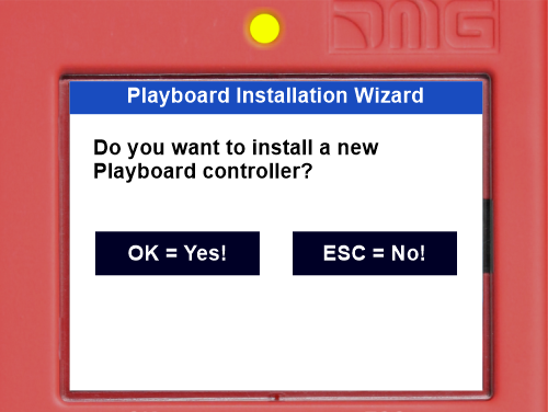
Confirm by pressing OK and select “Machine / VVVF Autotuning:
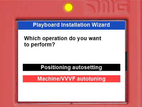
Insert the requested parameter and move on to the next one by pressing the Right Arrow.
The list of VVVF Parameter is:
| Parameter | Description | Gearless Motor | Geared Motor |
|---|---|---|---|
| P01 - Motor Poles | Insert Motor Pole's number | X | X |
| F03 – Maximum Speed | Insert max motor Speed [RPM] (Motor Plate) | X | X |
| F04 – Rated Current | Insert Rated motor speed [Hz] (Motor Plate) | X | X |
| F05 – Rated Voltage | Insert Rated motor voltage [V] (Motor Plate) | X | X |
| P08 – M-%X | Insert value 10 % | X | |
| P07 – M-%R1 | Insert value 5 % | X | |
| P06 – M-No Load Curr. | Insert value 0 [A] | X | |
| P03 – Motor Rated Current | Insert rated current [A] (Motor Plate) | X | |
| P02 – Motor Rated Cap | Insert rated power [kW] (Motor Plate) | X | |
| C11 – High Speed | Insert high speed [Hz] (Motor Plate) | X | |
| C10 – Middle Speed | Insert middle speed [Hz] (Inspection speed) | X | |
| C07 – Creep Speed | Insert low speed [Hz] (10% of C11) | X | |
| L01 – PG select | Set motor Encoder type: (VVVF Optional Boards) | X | X (*) |
| L02 – PG resolution | Insert Motor Encoder Resolution | X | X (*) |
(*) Closed loop only
Last parameter is different according Motor Type:
GEARLESS motor:
 Select 4 : Static Tuning
Select 5 : Dynamic tuning (only if free from ropes)
GEARED motor:
 Select 3
In case of any problem go to the Fault menu to identify the Problem (§ Motor Tuning Errors)
At the end of the procedure, press the up/down button and check the correct elevator car movement direction; if not correct, invert values of parameters E98 and E99.
For closed loop installations, in the <I/O Status>, VVVF IN/OUT menu, check that the VVVF motor encoder value (4/7) is positive (+) during upward movement and negative (-) during downward movement when the FWD (1/7) command is activated. If not, invert a channel in the motor encoder of the VVVF.
| L01 | Encoder specifications | Encoder board | Motor | |
| A/B Output channel | Absolute Signal | |||
| 0 | Open collector / Push-Pull | = | OPC-PG3 | IM |
| Line Driver | = | OPC-PMPG | ||
| 1 | Open collector / Push-Pull | Z | OPC-PG3 | IM & PMSM |
| 4 | Sine differential (1Vpp) | EnDat2.1 (ECN1313) | OPC-PS or OPC-PSH | PMSM |
| 5 | Sine differential (1Vpp) | ERN1387 | OPC-LM1-PR | PMSM |
| 6 | Sine differential (1Vpp) | BISS-C (Sendix 5873) | OPC-PS or OPC-PSH | PMSM |
| 7 | Sine differential (1Vpp) | SSI (ECN1313) | OPC-PS or OPC-PSH | PMSM |
| 8 | Sine differential (1Vpp) | Hiperface (SRS50) | OPC-PSH | PMSM |
| Code | Description | |
|---|---|---|
| OC1 | Overcurrent during acceleration | The inverter momentary output current exceeded the overcurrent level. |
| OC2 | Overcurrent during deceleration | |
| OC3 | Overcurrent during running at a constant speed | |
| EF | Ground fault | Zero-phase current caused by ground fault in the output circuit has exceeded the allowable limit. (30kW or above) |
| OV1 | Overvoltage during acceleration | The DC link bus voltage exceeded the overvoltage detection level. |
| OV2 | Overvoltage during deceleration | |
| OV3 | Overvoltage during running at a constant speed | |
| LV | Undervoltage | The DC link bus voltage dropped below the undervolt detection level. age |
| Lin * | Input phase loss | An input phase loss occurred or the Interphase voltage unbalance rate was large. |
| OH1 | Heat sink overheat | The temperature around the heat sink has risen abnormally. |
| OH2 | External alarm | The external alarm THR was entered. (when the THR "Enable external alarm trip" has been assigned to any digital input terminal) |
| OH3 | Inverter internal overheat | The temperature inside the inverter has exceeded the allowable limit. |
| OH4 | Motor protection (PTC/NTC thermistor) | The temperature of the motor has risen abnormally. |
| DBH | Braking register overheat | The temperature of the Braking resistor has exceeded allowable limit. |
| OL1 | Overload of motor 1 | The electronic thermal protection for motor overload detection was activated. |
| OLU | Inverter overload | The temperature inside the IGBT has risen abnormally. |
| OS | Over speed prevention | The motor speed is higher than maximum speed * L32. |
| PG | Broken wiring in the PG | The motor speed is higher than maximum speed * L32. |
| nrb | NTC wire break error | Detected a wire break in the NTC thermistor detection circuit. |
| Er1 | Memory error | An error has occurred when writing data to the inverter memory. |
| Er2 | Keypad communications error | A communications error has occurred between the key and the inverter. pad |
| Er3 | CPU error | A CPU error or LSI error has occurred. |
| Er4 | Option communications error | A communications error has occurred between the connected option card and the inverter. |
| Er5 | Option error | An error was detected by the connected option card (not by the inverter). |
| Er6 | Operation protection | An incorrect operation was attempted. |
| Er7 | Tuning error | Auto-tuning or Magnetic Pole Position Offset tuning has failed, resulting in abnormal tuning results. |
| Er8 | RS-485 communications error (port 1) | A communications error has occurred during RS-485 communication. |
| ErP | RS-485 communications error (port 2) | |
| OPL | Output phase loss | An output phase loss occurred. |
| ErE | Speed mismatching | The reference speed and the detection speed are different. |
| ErF | Data saving error during undervoltage | When the undervoltage protection was activated, the inverter failed to save data, showing this error. |
| ErH | Hardware error | The LSI on the power printed circuit board has malfunctioned due to noise, etc. |
| Ert | CAN open communication error | A communications error has occurred during CANopen communication. |
| ECF | EN1, EN2 terminals circuit error | An abnormality was diagnosed in EN1, EN2 terminals circuit. |
| Ot | Over torque current | Reference torque current became excessive. |
| DBA | Braking transistor broken | Detection of an abnormality in the brake transistor |
| bbE | Brake confirmation | The inverter detects mismatch between the brake control signal and brake detection (feedback) signal. |
| Eo | EN1, EN2 terminals chattering | Detected collision between ENOFF output and EN1/EN2 terminals. input |
| ECL | Customizable logic error | A customizable logic configuration error has caused an alarm. |
| OH6 | Charging resistor overheat | The temperature of the charging resistor inside the has exceeded the allowable limit. inverter |
| rbA | Rescue by brake alarm | No movement detected during rescue operation by brake control. |
| tCA | Reaching maximum numbers of trip counter | The number of trip direction changes has reached the preset level. |
| SCA | Short-circuit control error | The inverter detects mismatch between the short-circuit control signal and short-circuit detection (feedback) signal. |
| LCO | Load-cell overload | Load-cell function has detected overload situation by means of preset level. |
| Code | Alarm name | Subcode | Description |
|---|---|---|---|
| OC1 | Overcurrent during acceleration | 1 | Overcurrent protection (OCT interruption) - Normal overcurrent |
| 2 | Overcurrent protection (OCL interruption) - Normal overcurrent | ||
| OC2 | Overcurrent during deceleration | 3 | Short circuit protection - Overcurrent at start |
| 4 | Ground fault protection - Overcurrent at start | ||
| OC3 | Overcurrent during constant speed | 5 | Detection signal failure (FAULT signal) - Gate circuit |
| 11 | Detection signal failure (OCT signal) - Detection circuit (PPCB) | ||
| 12 | Detection signal failure (OCL signal) - Detection circuit (PPCB) | ||
| OV1 | Overvoltage during acceleration | 1 11 | Overvoltage Protection (OVT signal) Detection signal failure (OVT signal) |
| OV2 | Overvoltage during deceleration | ||
| OV3 | Overvoltage during constant speed | ||
| Lin | Input phase loss | 1 | Rectifier diode protection level detection |
| 2 | Continuous operation tolerance level detection | ||
| OPL | Output phase loss | 1 | |
| OH1 | Cooling fin overheat | 1 | Cooling fin overheat (NTC2) |
| 3 | Converter overheat (NTC4) | ||
| 11 | Thermistor disconnection (NTC2) | ||
| OH2 | External fault | 0 | Protection through THR |
| OH3 | Overheat inside inverter | 0 | Internal air overheat (NTC1) |
| OH4 | Motor Protection (PTC thermistor) | 1 | PTC thermistor |
| 2 | NTS thermistor | ||
| OH6 | Charging resistor overheat | 1 | Charging resistor overheat Except for FRN0039LM2A-4 / FRN0045LM2A-4 |
| 11 | Thermistor disconnection (NTC3) | ||
| OL1 | Motor overload | 0 | Current detection electronic thermal |
| LV | Undervoltage | 1 | Undervoltage is occurred during gate ON |
| 11 | Minimum level of battery operation | ||
| dbH | DB resistor overheat | 0 | DB resistor overheat (F50 <-> F52) |
| 1 | DB transistor 2sec_ON continuously (Wrong R too high) | ||
| dbA | DB transistor failure detection | 0 | DB transistor failure detection |
| Er1 | Memory Error | 0x0001 | Alarm history destruction |
| 0x0002 | Standard function code | ||
| 0x0004 | User function code | ||
| 0x0008 | Hidden function code | ||
| 0x0010 | Program area error | ||
| 0x0040 | Reading mismatch (retry over) | ||
| 0x0080 | Writing mismatch (retry over) | ||
| 0x0100 | Extended area | ||
| 0x1000 | Adjustment value area | ||
| Er2 | Keypad panel communication error | 1 | Disconnection detection |
| Er3 | CPU error | 1 | CPU re-start processing |
| 1000 | Function code checksum error (RAM error) | ||
| 0x0001 | Standard function code error | ||
| 0x0002 | Hidden function code (u code) error | ||
| 0x0004 | Hidden function code (n code) error | ||
| 0x0008 | Adjustment valve function code error | ||
| 0x0010 | Extended area | ||
| 2000 | Fixed-cycle error | ||
| 0x0001 | L1 cycle error | ||
| 0x0004 | L3 cycle error | ||
| 0x0008 | L4 cycle error | ||
| 0x0020 | L6 cycle error | ||
| 0x0080 | LP cycle error | ||
| 3000 | Unjust cut in | ||
| 5001 | Outside RST input | ||
| 7001 | Stack area destruction | ||
| 9000 | Software failure detection | ||
| 0x0200 | Alarm QUE over | ||
| Er4 | Option communication error | 1 | Port A communication error There is no option |
| 3 | Port C communication error | ||
| 10 | An excess of installed option There is no option |
||
| Er5 | Option error | 0 | Option in-match |
| 1 | Completion signal ON (There is no option) | ||
| 10 | AIO PT EEPROM error (There is no option) | ||
| 26 | PR-PP position information error (only OPC-PMPG+L01=2) | ||
| 27 | PP position information starting error | ||
| 50 | No save area | ||
| 51 | Communication command error | ||
| 52 | Distinction code error | ||
| 53 | Check-sum error | ||
| 54 | Writing error | ||
| Er6 | Operation procedure error | 2 | Start check |
| 7 | Multi speed assigned error | ||
| 8 | Brake check (waiting time timeout) | ||
| 9 | |||
| 10 | No try magnetic pole position tuning | ||
| 11 | Output side contactor confirmation error | ||
| 12 | Lack of rating speed | ||
| 14 | Brake chack (assigned error) | ||
| 15 | Short circuit (SCC assigned error) | ||
| 16 | Rescue error |
| Code | Alarm name | Subcode | Description |
|---|---|---|---|
| Er7 | At induction motor tuning | 1 | Multi speed assigned error |
| 2 | R1 phase error | ||
| 3 | %X error | ||
| 6 | Output current error | ||
| 7 | Drive command OFF | ||
| 9 | BX terminal ON | ||
| 11 | Undervoltage (LV) detection | ||
| 15 | Alarm occur | ||
| 16 | Change of drive command | ||
| 19 | Others | ||
| 21 | I0 error | ||
| 24 | EN terminal | ||
| 25 | DRS terminal | ||
| Er7 | At current detection gain tuning | 32 | EEPROM writing error |
| 37 | STOP key_ON | ||
| Er7 | At magnetic pole position offset tuning | 51 | Tuning without motor |
| 52 | Magnetic pole position tuning result error | ||
| 53 | F42 setting miss | ||
| 54 | L04 mismatch | ||
| Er7 | At current detection offset tuning | 61 | EEPROM writing error |
| 62 | STOP key_ON | ||
| Er7 | Synchronous motor tuning error | 5058 | Amature resistance error (lower limit) |
| 5059 | Amature resistance error (upper limit) | ||
| 5060 | Ld error (lower limit) | ||
| 5061 | Ld error (upper limit) | ||
| 5062 | Lq error (lower limit) | ||
| 5063 | Lq error (upper limit) | ||
| 5080 | ACR gain error (upper limit) | ||
| 5081 | ACR gain error (lower limit) | ||
| Er8 | RS485 communication error | 0 | CH1 RS485 communication error |
| nrb | NTC thermistor disconnection detection | 0 | NTC thermistor disconnection detection |
| OS | Overspeed | 0 | Overspeed protection |
| pg | PG error | 1 | Disconnection detection by hardware |
| 2 | Z phase disconnection detection by software | ||
| 50 | Option – A/B phase (Sin) disconnection detection | ||
| 51 | Option – C/D phase (Sin) disconnection detection | ||
| 52 | Option – R phase (Sin) disconnection detection | ||
| 53 | Option – A/B phase (pulse) disconnection detection | ||
| 54 | Option – Z phase (pulse) disconnection detection | ||
| 55 | Option – U/V/W phase (pulse) disconnection detection | ||
| 60 | Option – watchdog time out | ||
| 61 | Option – serial encoder response time out | ||
| 62 | Option – CPU communiction CRC error | ||
| 63 | Option – CPU out of communciation error | ||
| 70 | Option – ABZ output error | ||
| 71 | Option – serial encoder each alarm | ||
| 72 | Option - memory access error | ||
| 73 | Option – culcuration error | ||
| 80 | Option – PG card setting error | ||
| ErE | Speed mismatch (speed deviation excess) | 1 | The marks of speed command and speed detection differ |
| 3 | Speed deviation exces (speed detection > speed command) | ||
| 5 | Speed detection continues being 0 | ||
| 7 | Speed deviation exces (speed detection < speed command) | ||
| ErF | Undervoltage data save error | 0 | Undervoltage data save error |
| ErP | RS485 2ch communication error | 0 | CH2 RS485 communication error |
| Ert | CAN communication error | 1 | Bus-off |
| 2 | Guarding timeout detection | ||
| OLU | Inverter overload | 1 | IGBT protection |
| 2 | Inverter thermal Only FRN0060LM2A-4 <-> FRN0091LM2A-4 |
||
| 10 | ΔTj-c ≥ 60 °C | ||
| ECF | EN circuit error | 10 | EN input error (_EN1A=L, EN2A=L) |
| 11 | EN input error (_EN1A=H, EN2A=H) | ||
| 5000 | Diagnosis circuit error | ||
| 5010 | P5S power supply failure | ||
| 5020 | CPU diagnosis: Port setting diagnosis | ||
| 5030 | CPU diagnosis: ROM diagnosis | ||
| 5040 | CPU diagnosis: RAM diagnosis | ||
| 5050 | CPU diagnosis: sequence monitor | ||
| ECL | Customization logic malfunction | 0 | Customization logic error |
| Err | Simulated failure | 9998 | Simulated failure |
| Ot | Torque excessive error | 0 | Torque excessive error |
| bbE | Mechanical brake error | 11 | BRAKE 1 error |
| 12 | BRAKE 2 error | ||
| Eo | EN terminal error | 0 | EN terminal error |
| rbA | Rescue speed detection error | 0 | Rescue speed detection error |
| tCA | Direction switch limit arrival | 0 | Direction switch limit arrival |
| SCA | Short circuit error | 0 | Short circuit error |
| Lco | Load cell error | 0 | Load cell error |
| EF | Ground protection | 0 | Three phase current Only FRN0060LM2A-4 <-> FRN0091LM2A-4 |
In old motors the auto-tuning may fail: in these cases the auto-tuning type 1 (at point 10 select P04 = 1) can be executed but in this case the values P06 and P12 must be manually entered.

Typical values of P06 are between 30% and 70% of P03.
 F.r. = Frequency rated
S.s. = Speed synchronous
S.r. = Speed rated
Acceptable values of P12 are between 0.5 and 5 Hz.
For instance, for a 4-pole motor, the Rated Frequency is 50 Hz, the synchronous speed is 1500 rpm and the Rated Speed is on the motor nameplate (always in revolutions per minute).
GEARLESS motor
In case of a problem “Error 52 = er7 Error VVVF” will show in the MENU ERRORS. In this case please check the connections of the motor encoder, clear the errors in the “Errors” menu and repeat the poletuning procedure from point 14.
After the poletuning procedure try to move the elevator in maintenance in up and down for some motor revolutions. If it moves correctly the procedure is over, otherwise, in the event of an error of the VVVF (ere or Ocx or Os), reverse the two motor phases changing the VVVF’s H190 parameter, clear the errors in the “Fault” menu and repeat the poletuning procedure.
Instructions for Software update
FileName.PP2 or .PP4
Insert the USB device into the slot, waiting for the message as in the Figure 1.
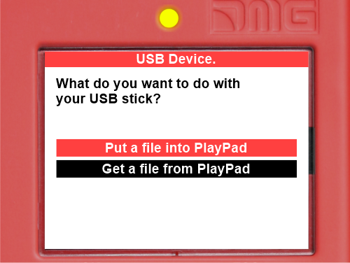 (Figure 1)
Select “Put a file into PlayPad” (default), press OK button. Window changes into Figure 2.
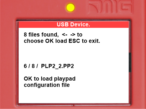 (Figure 2)
Follow the instruction on screen and select the .PP2/4 file (in the example PLP2_2.PP2) and press OK. Window changes into Figure 3
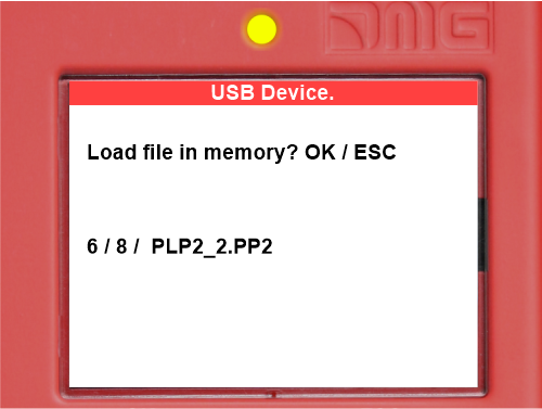 (Figure 3)
Press OK to confirm the update process. Window changes into Figure 4
 (Figure 4)
At the end of Procedure you have to remove the USB (Figure 5 or Figure 6 will be appear).
 (Figure 5)
 (Figure 6)
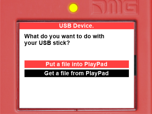 (Figure 7)
Window changes into Figure 8.
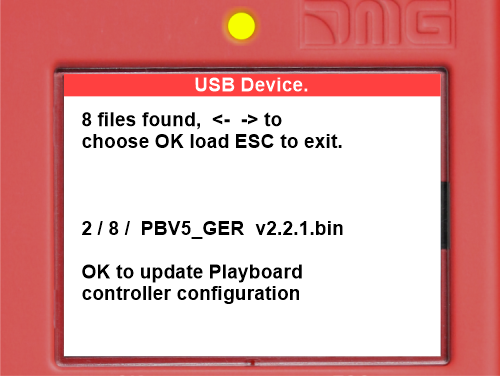 (Figure 8)
Follow the instruction on screen and select the *.bin file and press OK. Window changes into Figure 9.
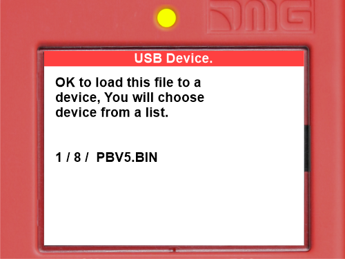 (Figure 9)
Press OK to confirm the update process. Window changes into Figure 10, wait for a while.
 (Figure 10)
Select the Device (or device group) to update and press OK (Figure 11)
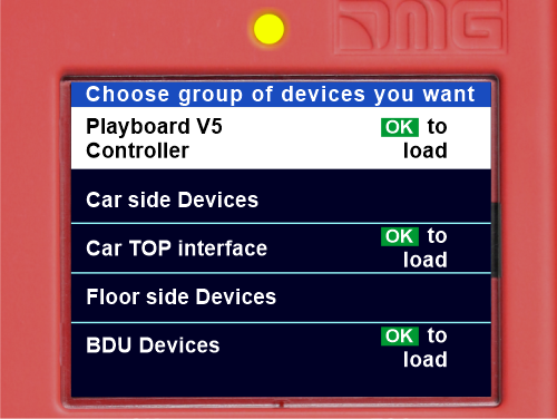 (Figure 11)
Window changes into Figure 12: wait until the process is completed. If you need to press any arrow button to switch on the backlight.
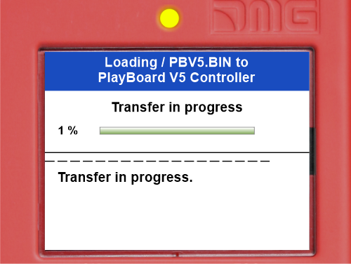 (Figure 12)
When the process ends (Figure 13) press Esc button until the windowshows “Please remove USB Device” (Figure 14).
 (Figure 13)
 (Figure 14)
| Device | Time needed for updating SW |
|---|---|
| Mother board (Playboard Controller) | 3 minutes |
| PlayPad 4.0 | 1 minute |
| TOC Board (Car TOP Interface) | 1 minute |
| DMCPIT Board (Car COP Interface) | 1 minute |
| Serial Pushbuttons Interfaces (BDU Devices) | 30 seconds |
| Expansion boards (PIT8 / 16RL / 16IO) | 30 seconds |
(Table III.1 – Timing for SW update)


