(v 1.3)
Safety and usage cautions
Before installing our products, we recommend you to consult the section about safety and usage cautions at the link below

For each described situation, it is necessary to comply with the applicable laws and regulations. This device is a low-power radio transceiver. When in operation, it transmits and receives radio frequency (RF) energy.
The device generates magnetic fields; therefore, it must be kept away from magnetic media such as floppy disks, tapes, etc. Operation near electrical and electronic equipment such as radios, telephones, televisions, and computers may cause interference.
PRECAUTIONS
To ensure safety, operator well-being, and proper device operation, the system (including cables) must be installed in a location free from or distant from:
• Dust, moisture, high heat, and direct exposure to sunlight.
• Objects emitting heat, which could damage the enclosure or cause other issues.
• Objects generating strong electromagnetic fields (e.g., Hi-Fi speakers).
• Liquids or corrosive chemicals.
ENVIRONMENTAL CONDITIONS
Operating temperature: -10°C to +50°C
Relative humidity: 20% to 80% (non-condensing)
Note: For the battery, the recommended temperature range is 0°C to +45°C. Outside this range, the device will continue to operate, but the battery will not charge.
Avoid rapid changes in temperature and humidity.
DEVICE CLEANING
Use a soft, dry cloth only. Do not use solvents.
VIBRATIONS OR SHOCKS
Avoid causing vibrations or shocks to the device.
INTERFERENCE
This device, like all wireless devices, is subject to interference that may affect its performance.
USE IN HOSPITALS
Turn off the device near medical equipment; interference may occur with pacemakers and hearing assistive devices.
Exercise caution when using the device in hospitals and healthcare facilities, as sensitive equipment may be affected by external RF signals.
In areas where indicated, the device must remain turned off.
USE NEAR EXPLOSIVE MATERIALS
Do not use the device in fuel storage areas, chemical plants, or locations with explosive gases or ongoing blasting operations.
All restrictions and applicable regulations must be strictly followed.
USAGE INSTRUCTIONS
Do not use the device in direct contact with the human body; maintain a minimum distance of 20 cm from the device and antenna.
Use only approved accessories. Consult manuals of any devices connected to this equipment. Do not connect incompatible devices.
POWERING ON AND OFF THE DEVICE
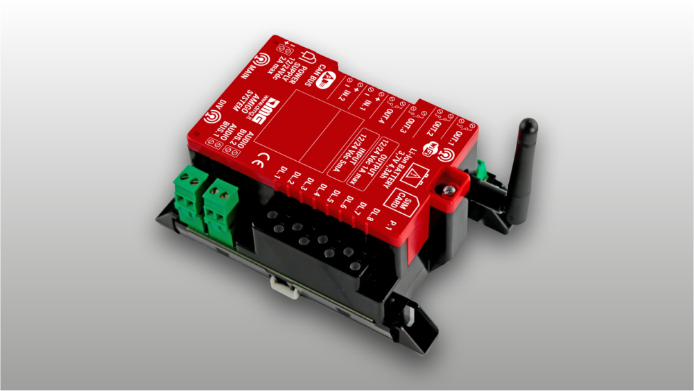
The device is equipped with an integrated lithium battery rated at 3.7 V – 4300 mAh.
The device is initially supplied with the battery disconnected.
The device features an internal circuit that, once the battery is connected, prevents it from powering on automatically (Transport Mode). The battery will become operational only after the device is powered via the 12/24 V DC input terminal.
To permanently switch off the device, the “Disconnect Battery” button is available in the Fusion App, allowing remote disconnection of the internal battery. Once confirmed, the battery will be disconnected and, when the input power supply is removed, the device will shut down permanently.
BACKUP BATTERY
WARNING: This device is equipped with a lithium-polymer backup battery rated at 3.7 V – 4300 mAh.
The battery may catch fire, explode, or cause severe burns. Do not disassemble, solder, burn, or immerse it in water. Keep out of reach of children.
Replace only with a battery of the same model. Battery replacement must be performed only by qualified personnel. The use of a different battery may result in fire or explosion hazards.
In Italy, batteries are classified as hazardous household waste and must be disposed of in accordance with current regulations, Legislative Decree No. 188 of 20 November 2008, implementing Directive 2006/66/EC on batteries, accumulators, and related waste, repealing Directive 91/157/EEC.
FIRST POWER-ON – INTEGRATED BATTERY CHARGING
At first power-on, the battery charge level may be incomplete due to transportation and warehouse storage.
A full battery charge is achieved after approximately 24 hours of device operation.
Monitor the battery voltage via the app. Full charge is reached when the battery voltage is approximately 4.1–4.2 V.

The crossed-out wheeled bin symbol shown on the product, battery, documentation or packaging indicates that batteries and electronic products must be disposed of separately at the end of their service life and must not be disposed of with normal household waste. It is the user’s responsibility to dispose of the equipment by delivering it to a designated collection point or service for the separate recycling of electrical and electronic equipment (RAEE) and batteries, in accordance with local regulations.
Proper collection and recycling help ensure that electrical and electronic equipment (AEE) is recycled in a manner that conserves valuable materials and protects the environment and human health from potential negative effects resulting from improper use, accidental breakage, damage and/or incorrect end-of-life treatment. For further information on where and how to dispose of RAEE, please contact your local authorities, your retailer, or your local waste disposal service.
Reduction of Restricted Substances
This device and any associated electrical accessories comply with applicable local regulations on the restriction of certain substances in electrical and electronic equipment, including the EU REACH and RoHS Directives, as well as those relating to batteries (when included).
System overview
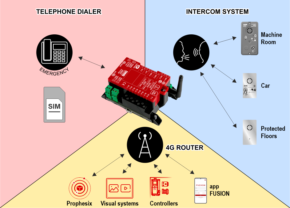
The system includes a router equipped to initiate emergency calls over both 4G (VoLTE) and GSM 2G networks using a SIM card. The device integrates a backup battery that ensures the autonomy required by the EN 81-28 standard.
To enable intercommunication between the several audio devices, the main device (dialer / router) generates two digital BUS two-wire (2Wire) that carry power, audio signals, and data. This results in simplified wiring, reducing the number of wires compared to the use of travelling cables that typically carry multiple wires, and easing installation.
The 2 Wire BUS allows communication between system devices in the following modes:
- Bidirectional telephone communication between trapped passengers (car, car roof, pit) and the rescue center (ref. EN 81-28).
- Bidirectional intercom communication between the car and the machine room (ref. EN 81-20).
- Bidirectional intercom communication between the fireman’s floor, protected floors, and the car (ref. EN 81-72).
- Bidirectional intercom communication between the evacuation floor, protected floors, and the car.
• 2G–4G–VoLTE communication for external emergency calls
• 4 programmable outputs via app
• 2 opto-isolated inputs 12/24 V (IN1: Alarm filter function, IN2: Alarm filter disable)
• 2 × 2-wire audio bus for connection of the audio devices; to the car via flexible travelling cable and in the shaft via drop cable
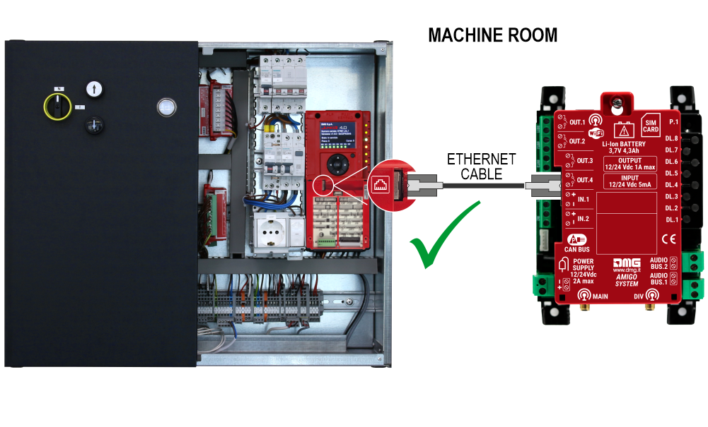
Connectivity
• Wi-Fi for controller connection
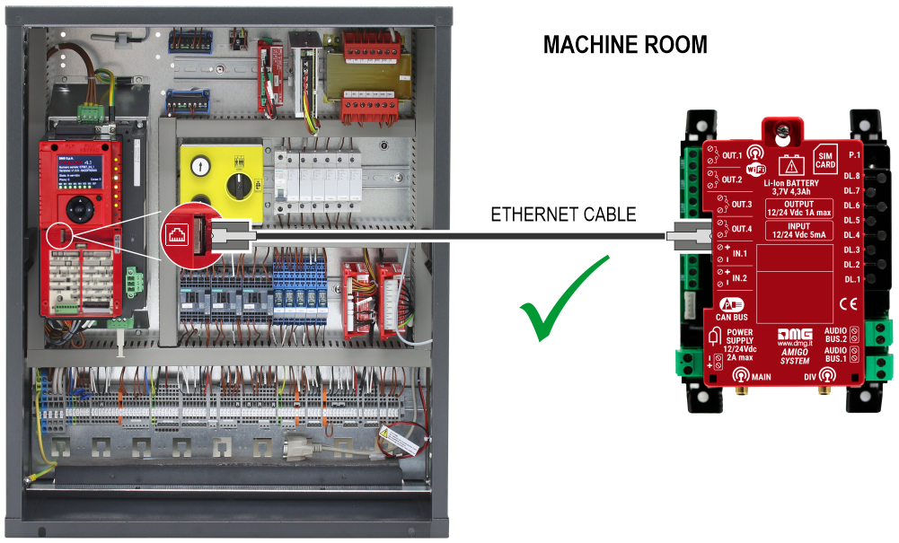
• Ethernet for controller or multimedia display connection
• 4G for remote connection via SIM card (shared with telephony)
Available product configurations
| Configuration | Complete configuration | Intercom only |
|---|---|---|
| Intended use | Internet + Emergency phone + Intercom | Intercom |
| Connectivity | Router 4G VoLTE LTE / GSM | No |
| Emergency phone | Yes | No |
| Micro-SIM connector | Yes | No |
| WiFi | Yes | No |
| Ethernet | Yes | No |
| Intercom (2-wire BUS) | Yes | Yes |
| FXS output | No | No |
| Configuration method | FUSION App (local) FUSION dashboard (remote) | Not required |
| Reference Standards | EN81-20 EN81-72 EN81-76 EN81-28 | EN81-20 EN81-72 EN81-76 |
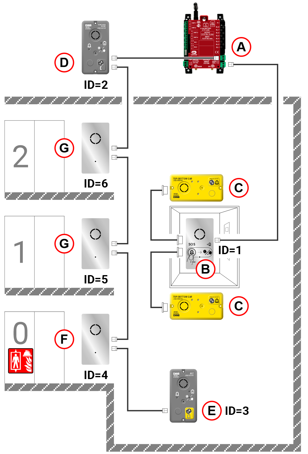
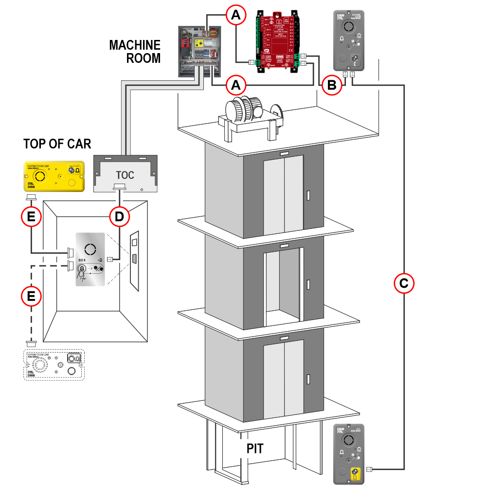
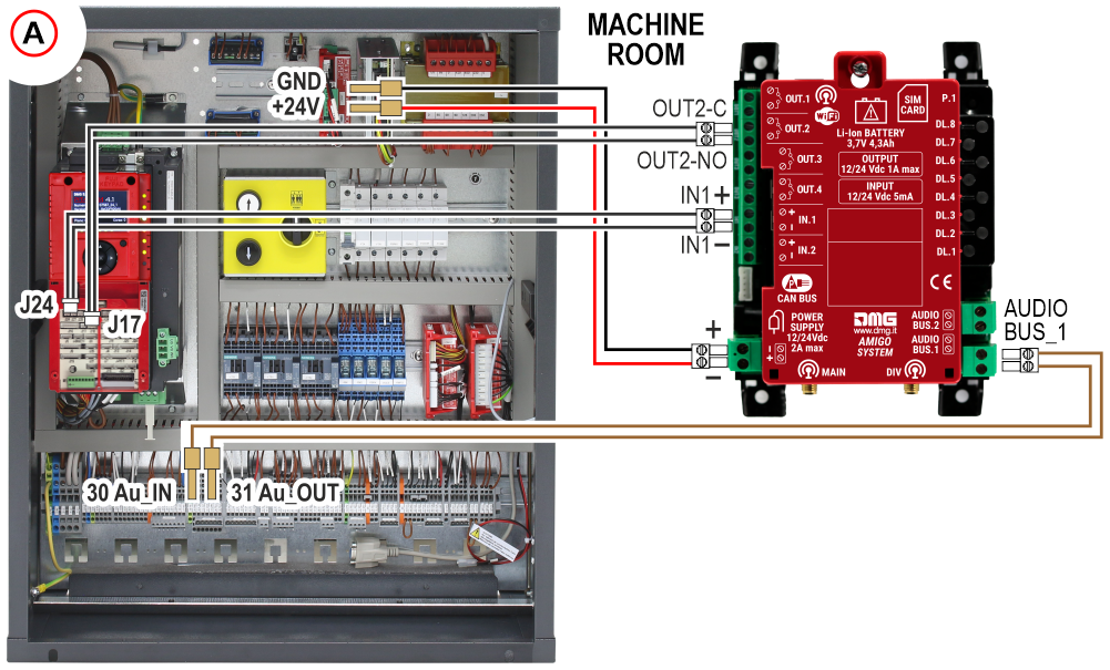
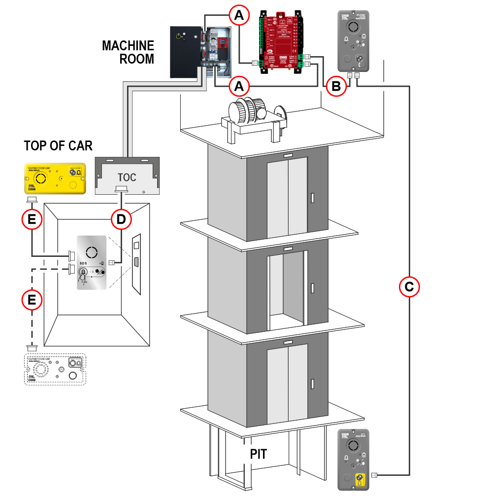
A) Telephone dialer / Router in the Machine Room
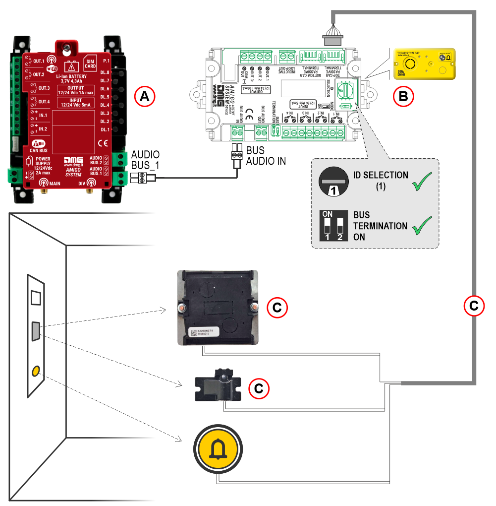
B) Audio device in the Car (ID=1)
C) Audio devices at the top and bottom of the cabin (*)
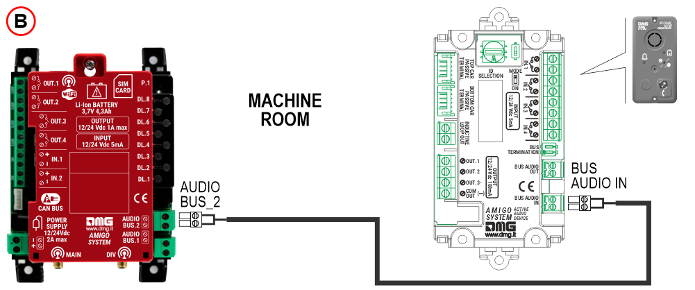
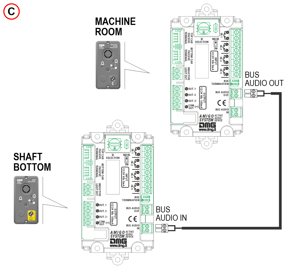
D) Audio device in the Machine Room (ID=2)
E) Audio device in the Shaft bottom (ID=3) (*)
F) Audio device at the firefighter’s floor (ID=4)
G) Audio device at any floor (ID=5/6/..)
(*) Warning : In firefighter lifts compliant with EN81-72, the pit audio device (or car-bottom audio device) shall be installed at a height ≥ 1m above the pit floor.
The solution with Amigo system and Pitagora 4.0 is described further below in section
Connecting AMIGO emergency telephone to the Pitagora 4.0 system
System components
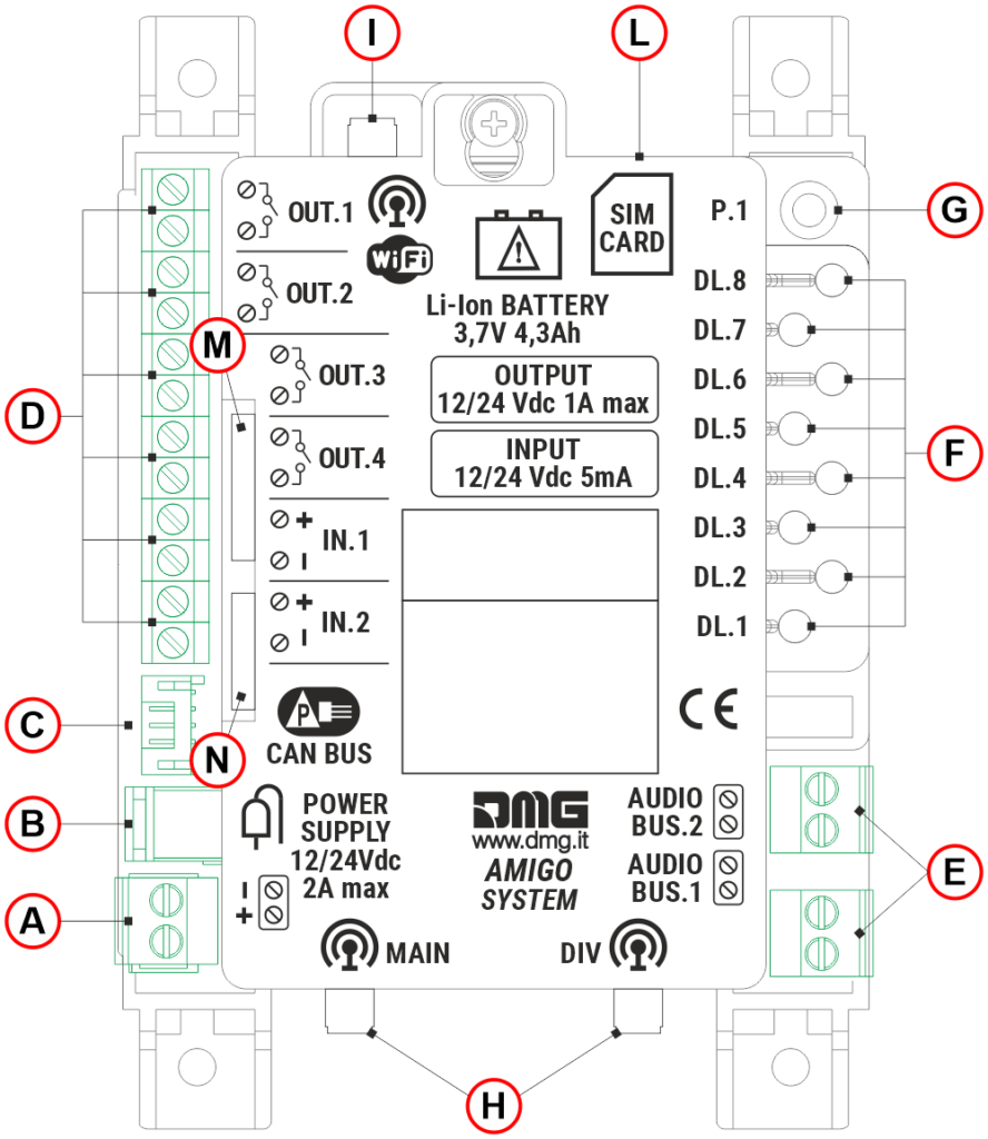
A) – Power supply input (via removable screw terminals)
B) – Power supply input (Jack DC connector)
C) – Not used
D) – 6 I/O terminal pairs, divided as follows:
– 4 programmable outputs for stand-alone configuration.
– 2 opto-isolated inputs (IN_1 – Alarm filter function / IN_2 – Alarm filter disable); a 12/24V DC supply is required for activation.
E) – 2 AUDIO BUS outputs for connecting the car audio device (via travelling cable) and the landing audio devices (via shaft drop cable)
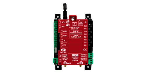
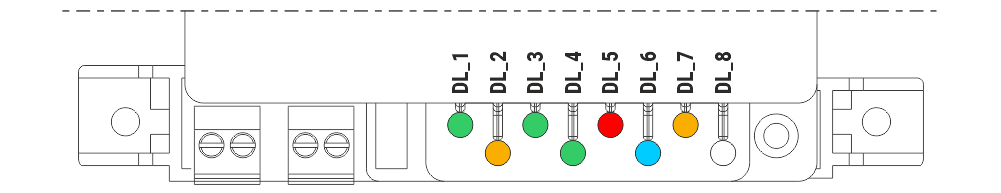
F) – 8 diagnostic LEDs
G) – Not used
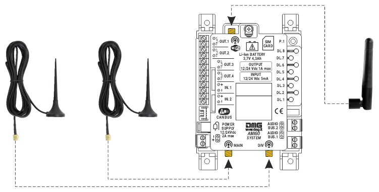
H) – 2 inputs for 4G mobile antenna (3m cable)
I) – Wi-Fi antenna (multimedia)
L) – SIM card for 4G connection
M) – LAN (RJ45 connector)
N) – FXS out (for future use)
Alarm Filter (§ 4.1.5 of EN 81-28 norm)
If available from the controller (or from another device on the system), information about door status (car and landing) and car presence at the floor can be used to filter out false alarms (see § 4.2.1 of EN 81-28).
To fully comply with EN 81-28, the AMIGO telephone dialer must also be connected to a Rescue Service (Call Center or similar).
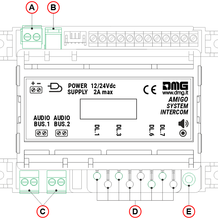
A) – Power supply input (via removable screw terminals)
B) – Power supply input (Jack DC connector)
C) – 2 AUDIO BUS outputs for connecting the car audio device (via travelling cable) and the landing audio devices (via shaft drop cable)
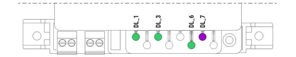
D) – 8 diagnostic LEDs (for the intercom system, only 4 LEDs are used).
E) – Press and hold the button for 3 seconds to adjust the volume of all audio devices; the selected volume level is indicated by LED DL6.
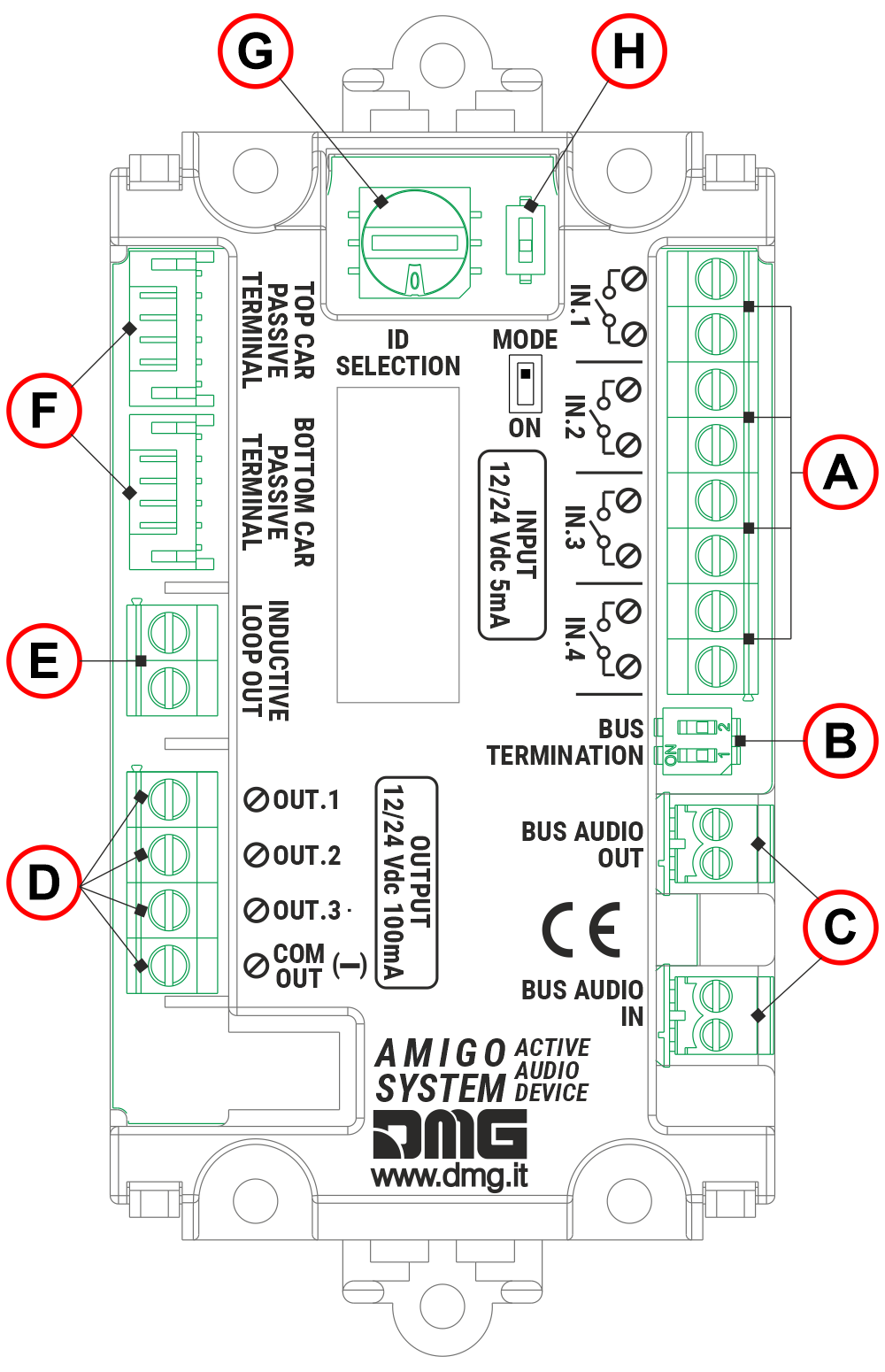
A) – 4 preset inputs (see table below)
B) – BUS termination dip-switch – must be enabled on the last audio device in the drop line (both cabin and landing devices)
C) – Audio BUS input and output for daisy-chaining up to 15 audio device
D) – 3 preset opto-isolated outputs (see table below). The outputs are not powered by the audio BUS line.
E) – Inductive loop (Currently unavailable)
F) – 6-pin JST connector for connecting the top and bottom car audio devices.
G) – Selector of the audio device (ID). Each audio device (maximum 15) must be assigned a unique ID address (see table below).
H) – Not used
| ID | Location of the audio device | Input function (A) | Output function (D) |
|---|---|---|---|
| 1 | Cabin | IN1 = Alarm call IN2 = Intercom IN3 = Alarm filter (see information below) IN4 = Local alarm reset | OUT1 = Alarm sent signal OUT2 = Alarm received signal OUT3 = Intercom communication active signal |
| 2 | Machie room | IN1 = Test call IN2 = Intercom IN3 = Not used IN4 = Local alarm reset | OUT1 = Not used OUT2 = Not used OUT3 = Intercom communication active signal |
| 3 | Pit | IN1 = Alarm call IN2 = Intercom IN3 = Alarm filter (see information below) IN4 = Local alarm reset | OUT1 = Alarm sent signal OUT2 = Alarm received signal OUT3 = Intercom communication active signal |
| 4 | Firefighters floor | IN1 = Not used IN2 = Firefighters intercom activation IN3 = Not used IN4 = Not used | OUT1 = Not used OUT2 = Not used OUT3 = Firefighters’ Key Switch Active |
| 5-9 A-F | Floor | IN1 = Not used IN2 = Push-to-talk intercom (PTT) IN3 = Not used IN4 = Not used | OUT1 = Not used OUT2 = Not used OUT3 = Intercom communication active signal |
Alarm Filter (§ 4.1.5 of EN 81-28 norm)
If available from the controller (or from another device on the system), information about door status (car and landing) and car presence at the floor can be used to filter out false alarms (see § 4.2.1 of EN 81-28).
To fully comply with EN 81-28, the AMIGO telephone dialer must also be connected to a Rescue Service (Call Center or similar).

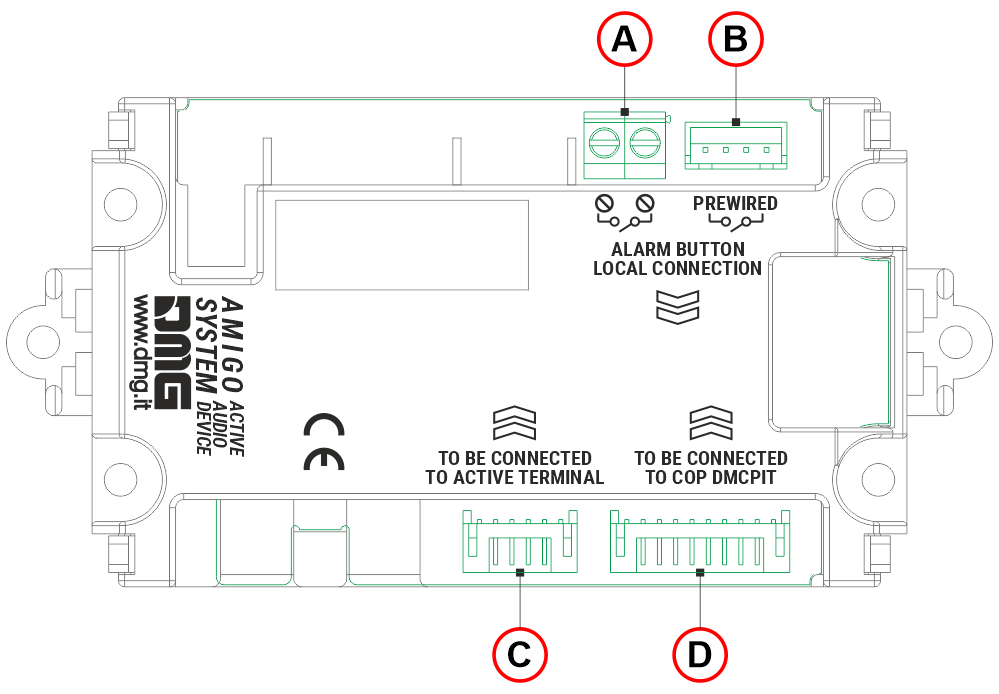
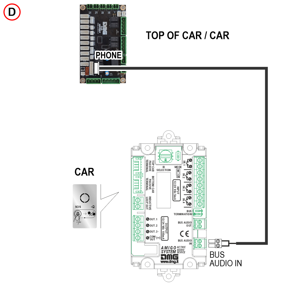
A) – 2-poles screw terminal block for connecting the push-button alarm
B) – 4-pin JST connector for connecting the push-button alarm
C) – 6-pin JST connector for connecting the audio device in the car
D) – Not used
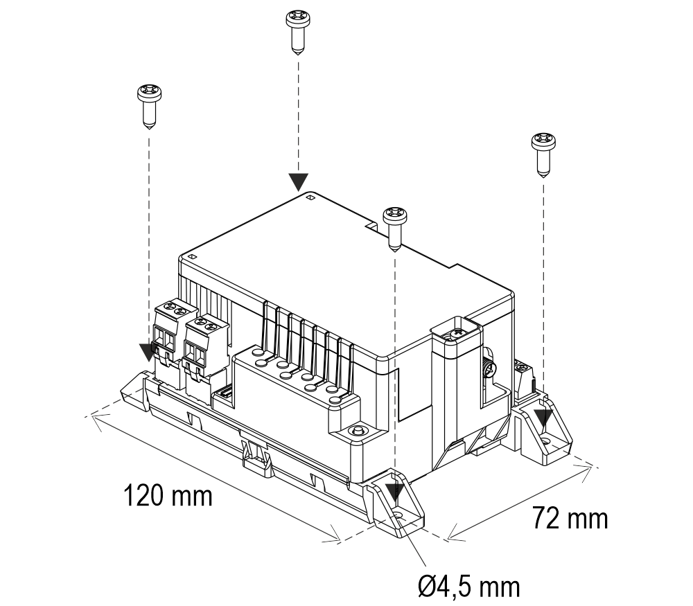
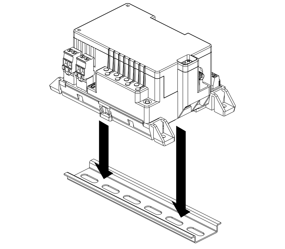
Installation of the telephone dialer
Transportation Function
Wiring instructions
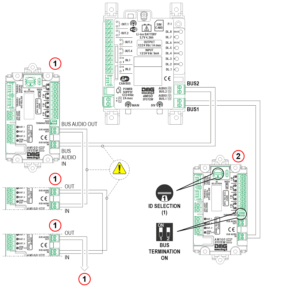
1) Audio devices at floors
2) Audio device in the cabin
Set the ID selector on the car audio device to 1 and Set the two BUS termination DIP switches to ON, as the car audio device is the end of the line.
Important: By default, the audio devices has the ‘BUS TERMINATION’ DIP switch set to OFF. If the audio device is the last device connected on the BUS line, this DIP switch must be set to ON.
 The cable used for connecting the audio devices through the 2-wire BUS requires the following specifications:
Shielding: Aluminum or braided copper
Poles and internal copper section: 2 X 0,75 mm²
Cable twisting: 40 mm
Maximum operating voltage: 300 V
Outer sheath diameter: 5,5 mm ± 0,5 mm
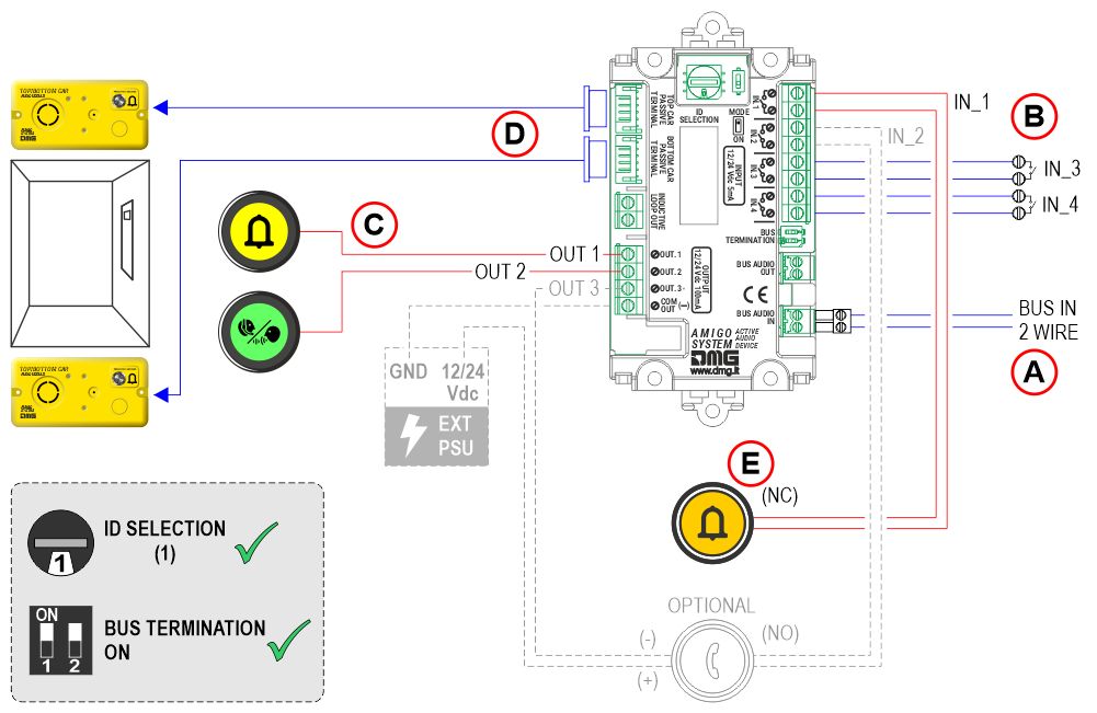
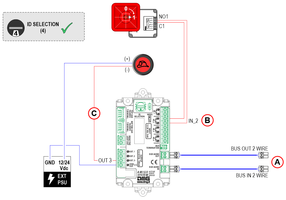
A)
BUS IN 2 wire – from the main device
B)
IN_1 – Alarm call
IN_2 – Intercom (optional)
IN_3 – Alarm filter
IN_4 – Local alarm reset
C)
OUT_1 – Alarm sent signal
OUT_2 – Alarm received signal
OUT_3 – Intercom communication active signal (optional)
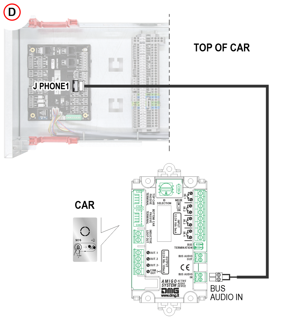
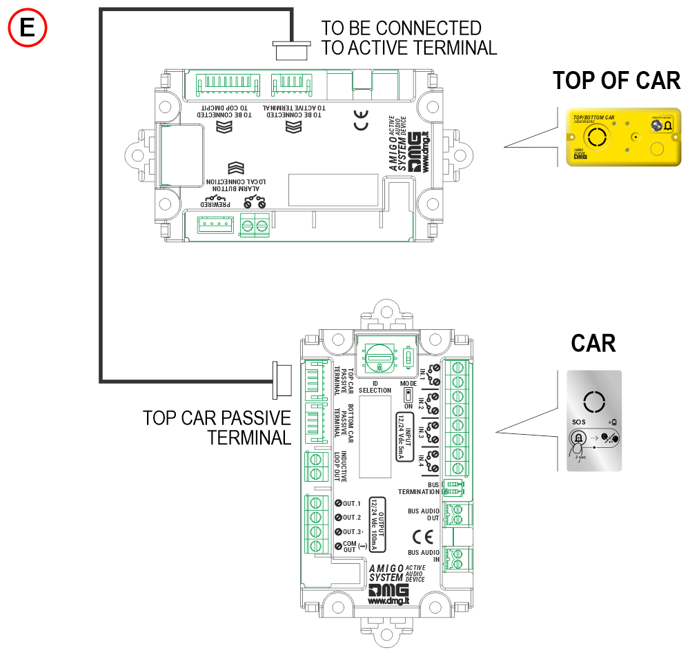
D) 6-pin JST connector for connecting the audio devices in the top / bottom of the cabin.
E) The polarity of the cabin alarm button input can be set using the parameter:
Parameters menu > Audio terminal > Code T3 (IN1)
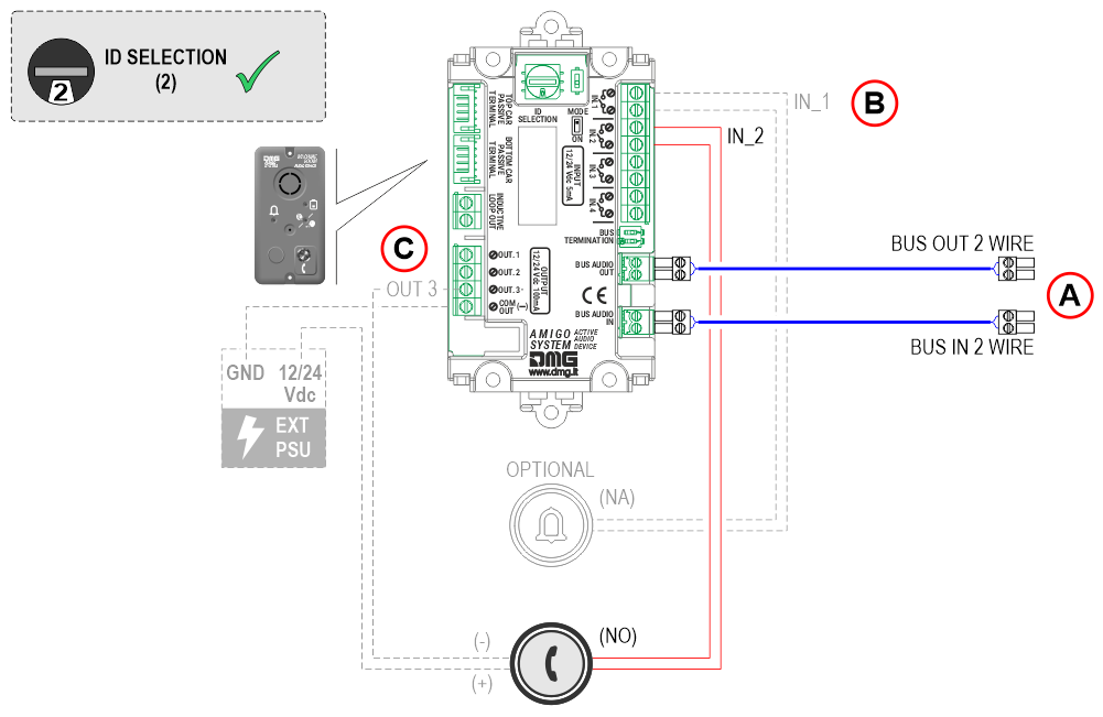
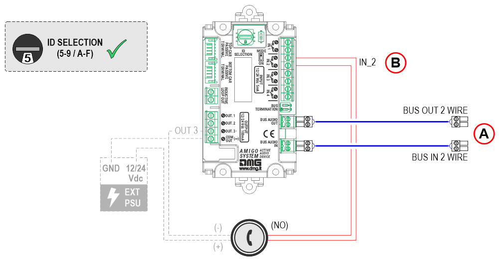
A)
BUS IN 2 wire – from the main device
BUS OUT 2 wire – to the next audio device
B)
IN_1 – Alarm call (optional)
IN_2 – Intercom
C)
OUT_3 – Intercom communication active signal (optional)
Important: By default, this audio device has the ‘BUS TERMINATION’ DIP switch set to OFF. If the audio device is the last device
connected on the BUS line, this DIP switch must be set to ON.
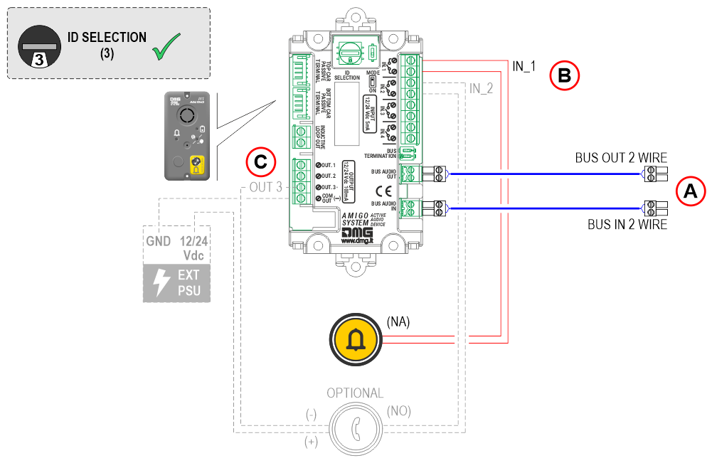
A)
BUS IN 2 wire – from the previous audio device
BUS OUT 2 wire – to the next audio device
B)
IN_1 – Alarm call
IN_2 – Push-to-talk intercom (optional)
C)
OUT_3 – Intercom communication active signal (optional)
Important: By default, this audio device has the ‘BUS TERMINATION’ DIP switch set to OFF. If the audio device is the last device connected on the BUS line, this DIP switch must be set to ON.
A)
BUS IN 2 wire – from the previous audio device
BUS OUT 2 wire – to the next audio device
B)
IN_2 – Input for Firefighters’ Intercom Activation
C)
OUT_3 – Firefighters’ Key Switch Active
Important: By default, this audio device has the ‘BUS TERMINATION’ DIP switch set to OFF. If the audio device is the last device connected on the BUS line, this DIP switch must be set to ON.
A)
BUS IN 2 wire – from the previous audio device
BUS OUT 2 wire – to the next audio device
B)
IN_2 – Push-to-talk intercom
Important: By default, this audio device has the ‘BUS TERMINATION’ DIP switch set to OFF. If the audio device is the last device connected on the BUS line, this DIP switch must be set to ON.
A) Audio device in the cabin
Connecting AMIGO emergency telephone to the Pitagora 4.0 system
 The audio module installed at the bottom of the car can replace the audio device located in the Pit.
Connection details
The connection may have already been made at the factory.
The connection may have already been made at the factory.
Connecting AMIGO emergency telephone to the Junior 4.0 system
 The audio module installed at the bottom of the car can replace the audio device located in the Pit.
Connection details
 The connection may have already been made at the factory.
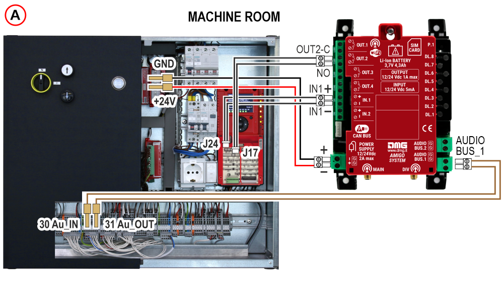
The connection may have already been made at the factory.
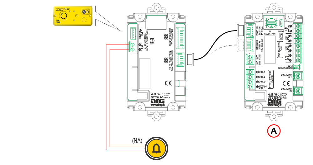
Retrofit in case of non-DMG telephony
A) Telephone dialer
B) Audio device in the top of cabin
C) Kit retrofit: JST 6P cable + Loudspeaker + Microphone
Diagnostic LEDs
The LED status is also displayed in the Fusion app.
| LED colour | Status | |
|---|---|---|
| Led DL1 – Device operation status | ||
| Green | Device status OK | |
| Orange | Device status warning | |
| Red | Device status fail | |
| Led DL2 – Data transmission | ||
| Orange | LED flashes if a data transmission is in progress | |
| Led DL3 – Power and battery status | ||
| Green | Power and battery status OK | |
| Orange | Power status OK and Battery status warning | |
| Red | Power status OK and Battery status fail | |
| Blue / Green | No power and Battery status OK | |
| Blue / Orange | No power and Battery status warning | |
| Blue / Red | No power and Battery status fail | |
| Off | No power and no battery | |
| Led DL4 – Network type (colour) | ||
| Green | 4G Network + VoLTE | |
| Orange | 4G Network (no VoLTE) | |
| Red | 2G / 3G network | |
| Off | No network signal | |
| Led DL5 – Data roaming enabled / disabled | ||
| Green | Roaming enabled | |
| Red | Roaming disabled | |
| Led DL6 – FXS output status and line status (in case of ring, the corresponding LED flashes) | ||
| Green | FXS output enabled | |
| Red | FXS output disabled | |
| White | Line in outgoing communication | |
| Cyan | Line in incoming communication | |
| Led DL7 – BUS2W status and communication status (in case of ring, the corresponding LED flashes) | ||
| Green | BUS output 2W active | |
| Orange | BUS output 2W fail | |
| Red | BUS output 2W warning | |
| Purple | Ongoing intercom communication | |
| White | Bus active and Line in outgoing communication | |
| Cyan | Bus active and Line in incoming communication | |
| Led DL8 – Connection type enabled (in case of active communication at the same time flashing LEDs alternately) | ||
| White | WiFi active | |
| Red | BLE active | |
| Green | Ethernet active | |
The LED status is also displayed in the Fusion app.
| LED colour | Status | |
|---|---|---|
| Led DL1 – Device operation status | ||
| Green | Device status OK | |
| Led DL3 – Power supply status | ||
| Green | Power supply status OK | |
| Led DL6 – Audio devices volume adjustment level | ||
| Red | Level 0 | |
| Green | Level 1 | |
| Blue | Level 2 | |
| White | Level 3 | |
| Led DL7 – Intercom communication status | ||
| Purple | Intercom communication active | |
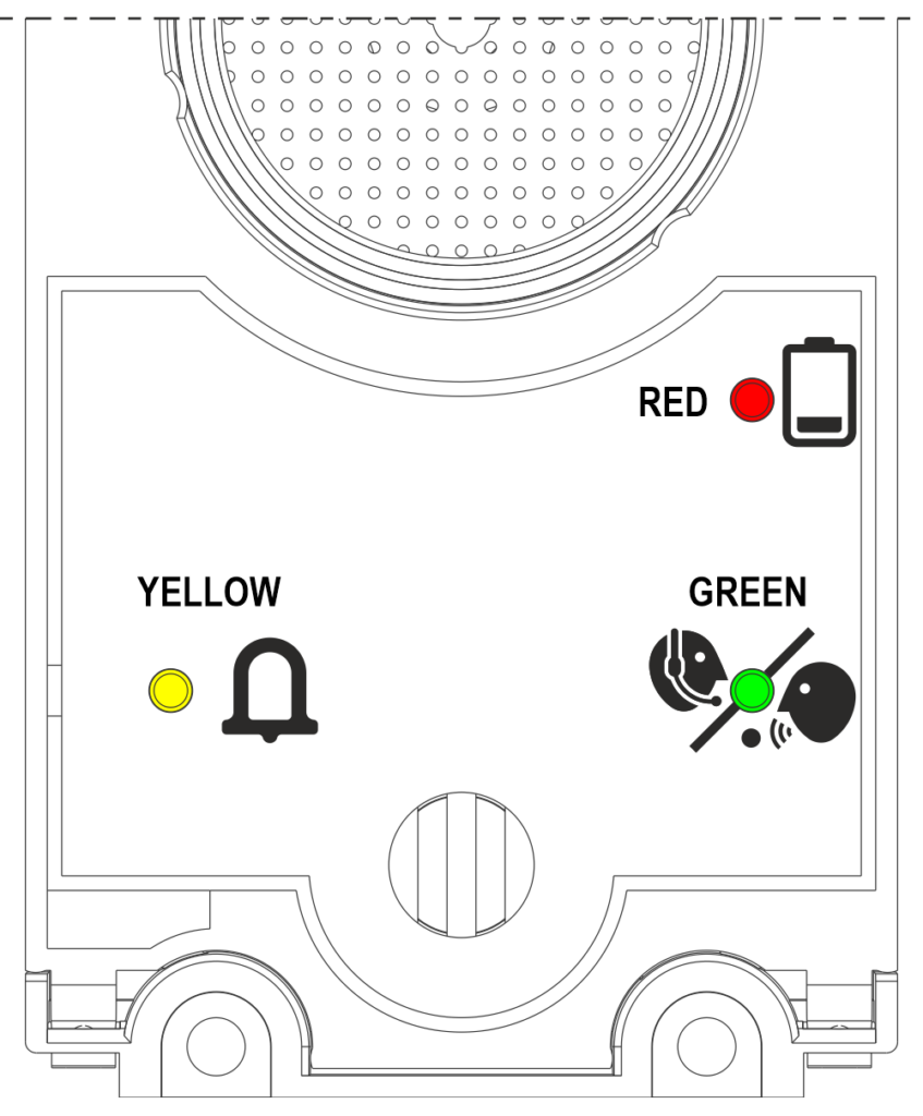
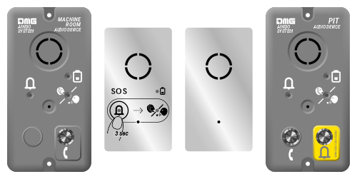
Yellow LED: Alarm sent
Green LED: Communication established
Red LED: Low battery
Programming via the FUSION app
FUSION is DMG’s app for programming, monitoring, and controlling its devices, both locally and remotely.
With the FUSION app, you can configure the AMIGO 4.0 device using a user-friendly wizard that guides you through the setup of both the router and telephony sections.
FUSION app general layout
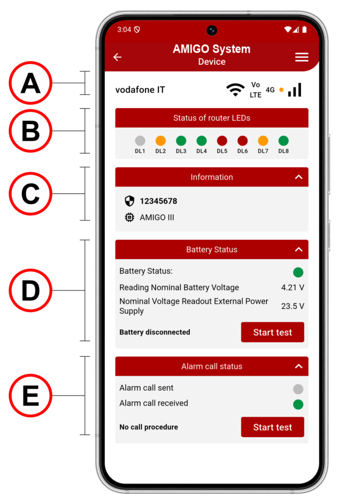
A)
• Mobile network operator name
• Wi-Fi signal
• VoLTE (Voice over LTE), if available
• Network type
• Network signal level
B)
• Status of router LEDs
C)
• Device serial number
• Firmware version
D)
• Battery information
• Power supply status
• Perform a battery test
E)
Call status indicated by LEDs, showing which alarm/service call is currently active.
When a call is initiated, the “Alarm Call Sent” LED turns orange, and when someone answers the call, the “Alarm Call Received” LED turns green.
By clicking “Start test”, a test call is executed, selected from the available call types.
Initial setup wizard
The setup wizard appears only at first startup.
After configuration, the device goes directly to the Home Page.
To reopen the wizard, a parameter reset is required.
2) Battery connection
The first two steps are performed offline and show how to insert the SIM card and connect the battery.
3) Turning on the device
After powering on the device, check LEDs DL1 and DL3 to verify that the device is ready for use.
4) Connect to the local WiFi network
Connect to the DMG_AMIGO_ network. Once connected, the LEDs and all other information will start being detected, whereas previously they were unavailable.
The wizard setup cannot continue until the Wi-Fi connection is established.
If a SIM with a PIN is inserted, network information (operator and signal) will only be visible after the PIN is entered.
5) Insert SIM PIN code
If the SIM PIN is locked, you will be prompted to enter it.
Once the SIM PIN is entered, the device automatically disables it, and the SIM will be unlocked without a PIN.
If the PIN is already unlocked, you can continue without entering it.
Other possible states include: SIM not inserted, incorrect PIN, or PUK code requested.
6) Wait for the device to register on the network
7) Data SIM roaming deactivation
In the following steps, you can disable the PIN request or enable/disable roaming.
Disabling the PIN can be useful to avoid entering it every time the device is used.
Roaming, usually disabled, should be enabled when using the device abroad; otherwise, calls might not be received.
8) Enable/Disable internet connection
Warning: If you disable the internet connection, you will not have remote control of the device.
9) APN configuration
Displayed only if the internet connection is enabled.
10) Check internet connection
APN configuration is essential. It can be set automatically, but if the connection doesn’t work, it can be manually changed.
If the APN is incorrect, the device will not connect to the Internet and only voice calls will be available. To verify that the APN is correct and the device is connected to the Internet, check that LED DL2 is lit.
11) Emergency call numbers
In these steps, phone numbers for calls must be entered.
In the “Emergency call numbers” section, you can add up to 6 emergency numbers, with at least the first one being mandatory. During an alarm call cycle, the numbers will be dialed in sequence.
12) Numbers self-diagnosis calls EN81-28
In the “Numbers for self-diagnosis calls” section, you can enter up to 3 numbers for automatic self calls. These calls are triggered automatically in case of periodic test 81-28.
13) Numbers for service / self-diagnosis calls
In the “Numbers for service calls” section, you can enter up to 3 numbers for automatic service calls. These calls are triggered automatically in case of issues such as low battery, power failure.
Attention: Ensure that the voicemail is deactivated for emergency contact numbers, both in cases of no answer and when the number is unreachable or the phone is off.
14) Verify alarm calls
15) Verify self-diagnosis EN81-28
In these steps, test calls can be made to verify the correct operation and configuration of the system.
Clicking on Test Call Alarm will call the emergency numbers set for alarm calls, while clicking on Test Call Service will start the test of service calls to the configured numbers.
These tests are optional and at the installer’s discretion.
Parameters menu
| Code | Description |
|---|---|
| G1.1 | Gateway output configuration – OUT 1 Configuration of OUTPUT 1 relay on the device with the following options: 0 – Disabled 1 – Same behavior Alarm Sent 2 – Same behavior Alarm Received 3 – Active in the absence of external power supply 4 – Active for the duration of the alarm call 5 – Active while pressing alarm buttons 6 – Active when there is no telephone line signal 7 – Active when the battery is discharged 8 – Remote Activation |
| G1.2 | Gateway output configuration – OUT 2 Description and option selection as in section G1.1 |
| G1.3 | Gateway output configuration – OUT 3 Description and option selection as in section G1.1 |
| G1.4 | Gateway output configuration – OUT 3 Description and option selection as in section G1.1 |
| G2 | Remote battery disconnect Parameter G2 allows remote battery disconnection for complete device shutdown. The Amigo 3 device is equipped with a battery power on/off control circuit. |
| G3.1 | Notification Call Filter – External Power Failure Alarm Calling Procedure Allows enabling or disabling the notification call in case of external power loss. |
| G3.2 | Notification Call Filter – Procedure Calling Alarm Connection Handsfree 2W Allows enabling or disabling the notification call for audio terminal disconnection. |
| G3.3 | Notification Call Filter – Calling Procedure External Power Failure Alarm Allows enabling or disabling the notification in case of external power loss. |
| G4 | Restart device Parameter for restarting the device. |
| G5 | Restore factory settings Parameter to reset the device to factory defaults. |
| G6 | Search and install updates Parameter for searching and installing firmware updates. |
| Code | Description |
|---|---|
| R1 | Data SIM Roaming Enable Data roaming on the SIM can be enabled or disabled. |
| R2 | APN Configuration APN configuration with automatic selection via internal database or manual input. |
| R3 | DTMF tone mode configuration |
| R4 | VoLTE enable/disable setting |
| Code | Description |
|---|---|
| C1 | Registration of a unique identification number (provided by the call center to the sent in case of alarm). – IMSI – ICC ID Sim – MAC – Editable field |
| C2 | Recording the phone numbers you want to call during the alarm cycle (currently 6 numbers). |
| C3 | Entry of the three numbers assigned for EN81-28 periodic test calls. |
| C4 | Recording service call number for service messages (e.g. low battery, power failure alarm). |
| C5 | Setting the Communication Protocol. – None – P100 |
| C6 | Setting the maximum number (1÷9) of alarm cycle attempts before the system returns to stand-by mode |
| C7 | Setting the time (0÷3 seconds) for pressing the alarm button of one of the devices before the dialer starts the alarm cycle. |
| C8 | Setting the Manual Test Time of the Alarm Button. |
| C9 | Set the interval of the periodic test call (EN_81-28). |
| C10 | Setting the Maximum Duration of Two-way Talk Time (3-15min) |
| C11 | Call Center Response Waiting Time (10…90sec) |
| C12 | Multiline Configuration. – 1 Amigo > 1 Car (Simplex) – 1 Amigo > 2 Cars (Multiplex) |
| C13 | Reset all alarms |
| Code | Description |
|---|---|
| M1 | Control Playback Pre-Recorded Audio Messages Plays the preloaded audio messages. |
| M2 | Choice of Primary Message Language Primary audio-message playback language selection. |
| M3 | Choice of Secondary Message Language Secondary audio-message playback language selection. |
| Code | Description |
|---|---|
| T1 | Number of Terminal Present on Bus Shows the number of the audio devices connected to the bus. |
| T2 | Terminal IDs and Volume configuration Shows the IDs of the connected audio device and the volume (0–3) for each device. |
| T3 | Polarity of Audio Terminal Inputs Setting the polarity of the audio devices’ inputs. |
| T4 | Not used |
Alarm Cycle
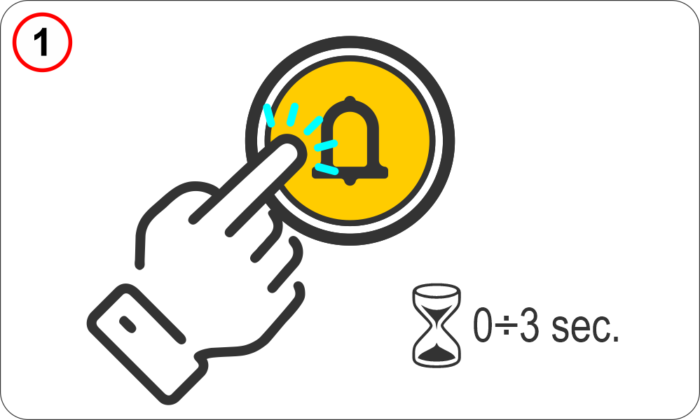 | The passenger trapped in the lift holds down the alarm button for a preset, adjustable time. Parameters menu > Dialer > Code C7 |
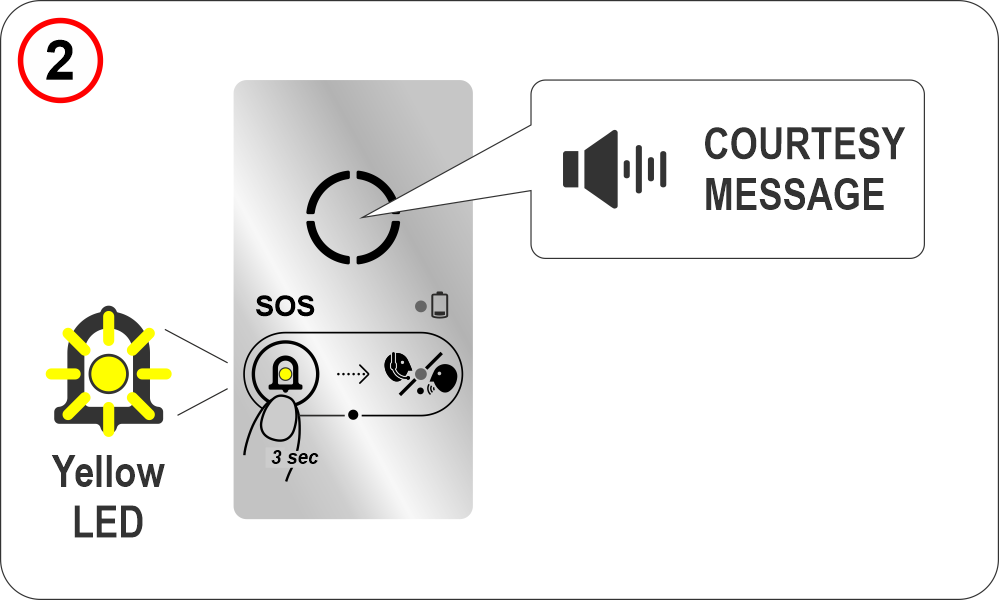 | When the alarm is generated, the yellow “alarm sent” indicator lights up on the audio device and the preset courtesy message is played. Parameters menu > Audio Messages > Code M1/M2 |
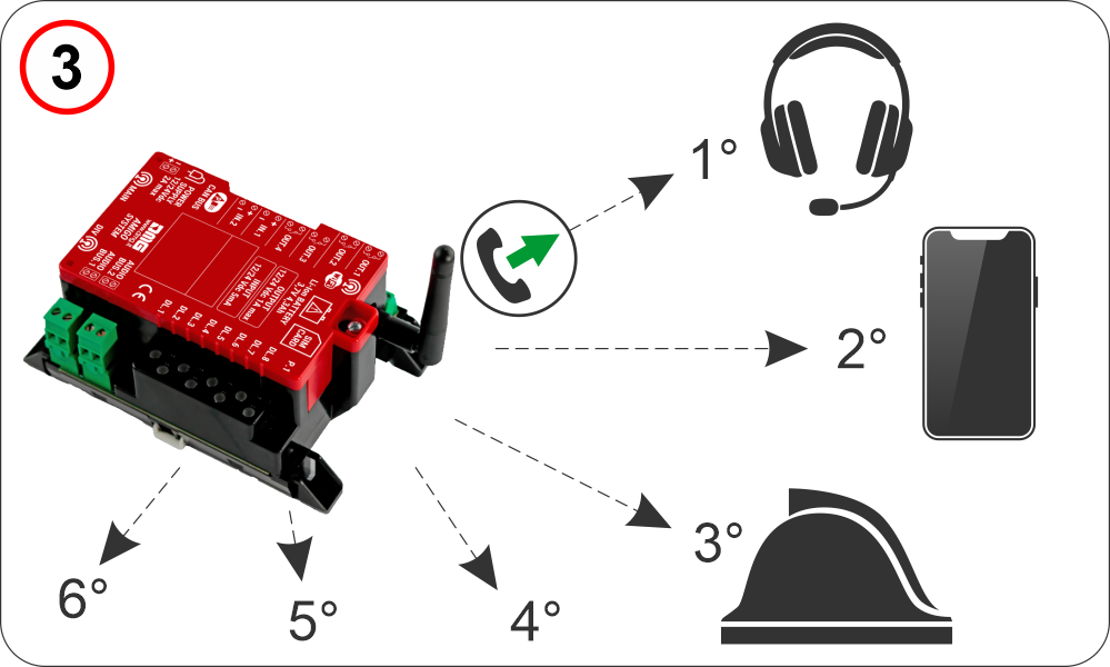 | The AMIGO emergency phone dials the first stored number. Parameters menu > Dialer > Code C2 If the communication protocol is set to P100 and the call center is enabled for DTMF tone communication, the lift identification sequence is transmitted as DTMF tones. Parameters menu > Dialer > Code C5 |
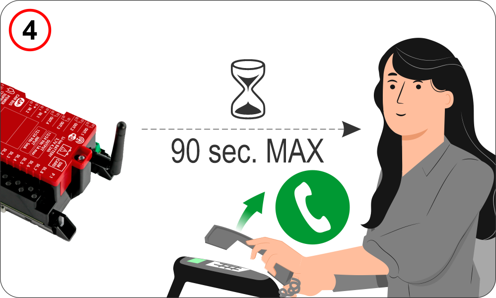 | The call must be accepted within a user-programmable time interval (Response Waiting Time) Parameters menu > Dialer > Code C11 otherwise the AMIGO emergency phone dials the second stored number (see the previous section). |
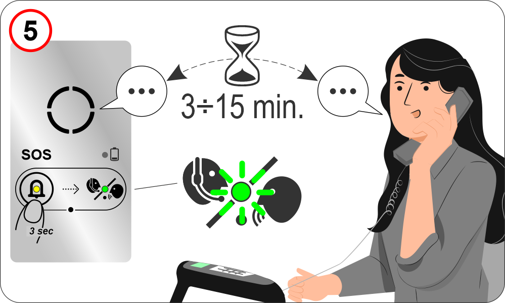 | Once the call is accepted, a two-way conversation is automatically established for a user-programmable duration (Two-way Talk Time). Parameters menu > Dialer > Code C10 The green “communication established” indicator lights up on the audio device. |
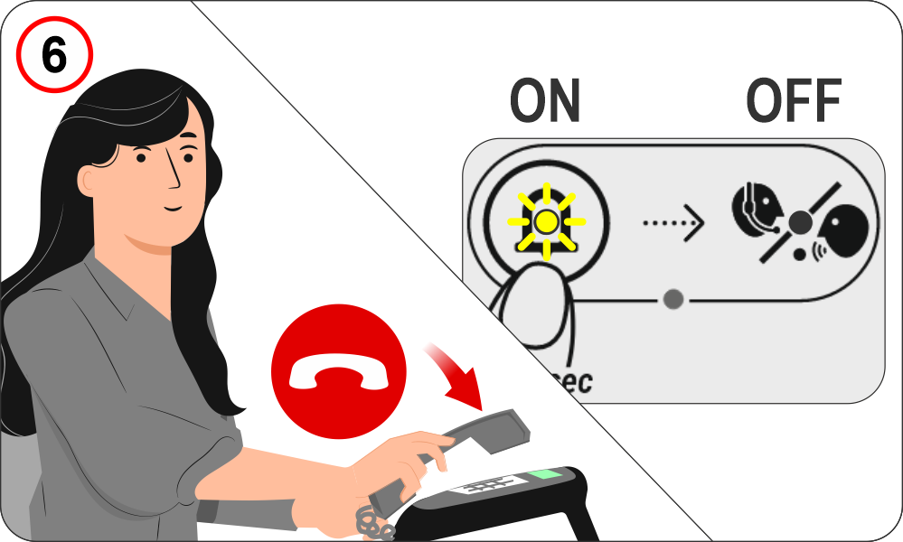 | Once the call is hung up, the “Alarm Sent” indicator remains lit, while the “Communication Established” indicator turns off (according to EN81-28 requirements). |
To turn off the “Alarm Sent” (yellow) indicator, the alarm must be reset, which can be performed in one of the following ways:
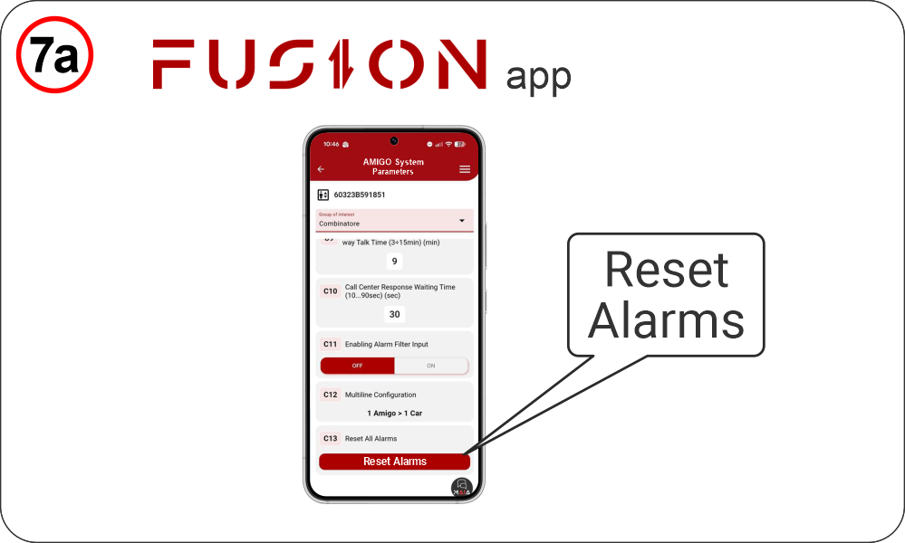 | Remotely – Fusion APP --------------------------------- Parameters menu > Dialer > Code C13 |
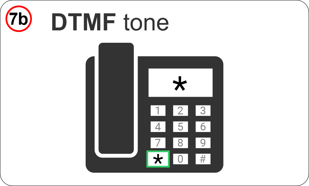 | Remotely – Phone DTMF tones --------------------------------- by calling the device back and sending the DTMF (*) tone. |
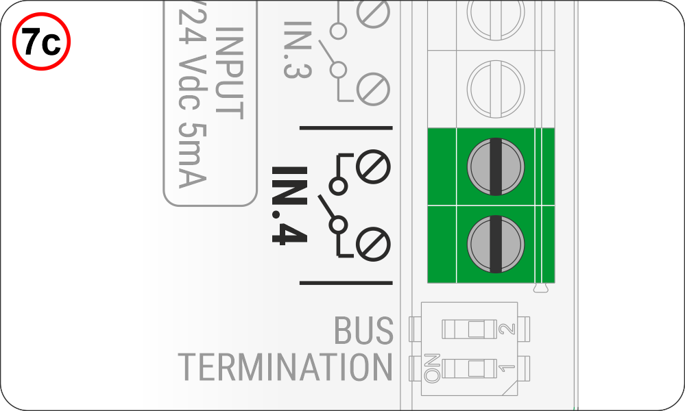 | Locally – IN4 contact --------------------------------- through the IN_4 contact on the audio device. In this case, a call to the rescue center is triggered, notifying them that the alarm has been reset locally (end-of-alarm call). |
Automatic test calls
Low Battery Call (EN81-28)
The Alarm System automatically reports upcoming battery depletion.
The call is triggered automatically when the voltage drops below 3.4V.
The call can be made in voice or data mode, depending on whether a protocol is configured.
Periodic Auto Test 81-28 Call (EN81-28)
The Alarm System automatically signals proper operation by periodically connecting to the Rescue Service, typically every 72 hours (3 days).
Parameters menu > Dialer parameters > Code C9
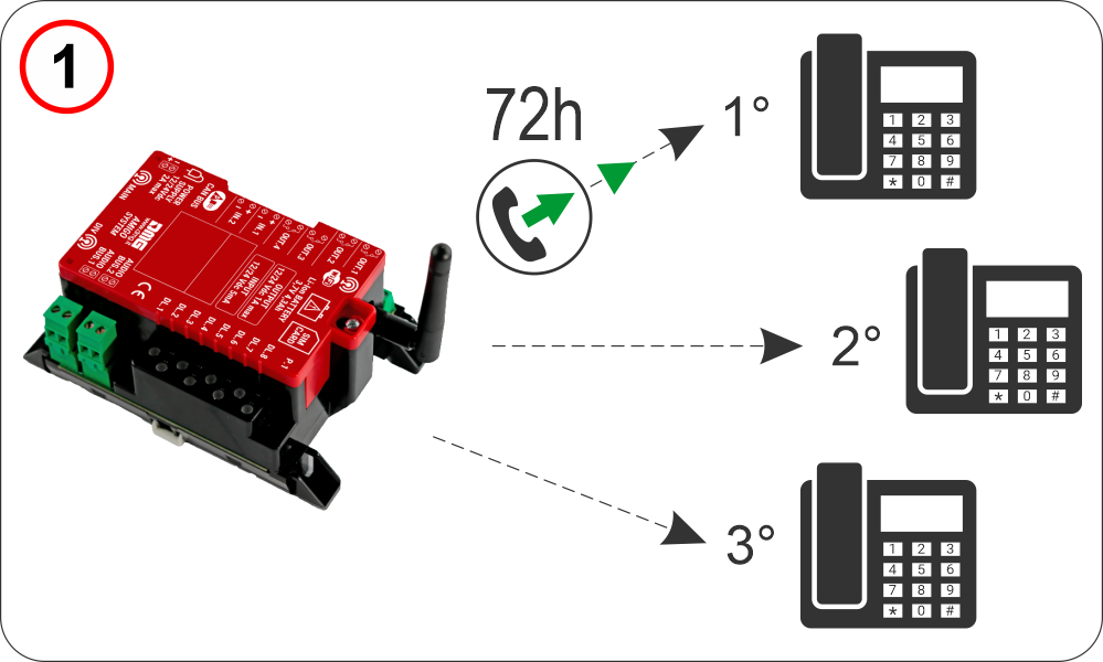 | The AMIGO emergency phone dials the first three stored numbers. Parameters menu > Dialer > Code C3 The call can be made in voice or data mode, depending on whether a protocol is configured. Parameters menu > Dialer > Code C5 |
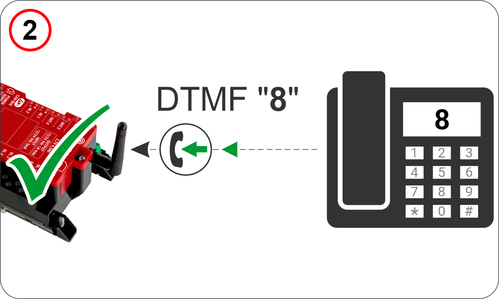 | For a call to be successful, the dialer expects the DTMF “8” tone. |
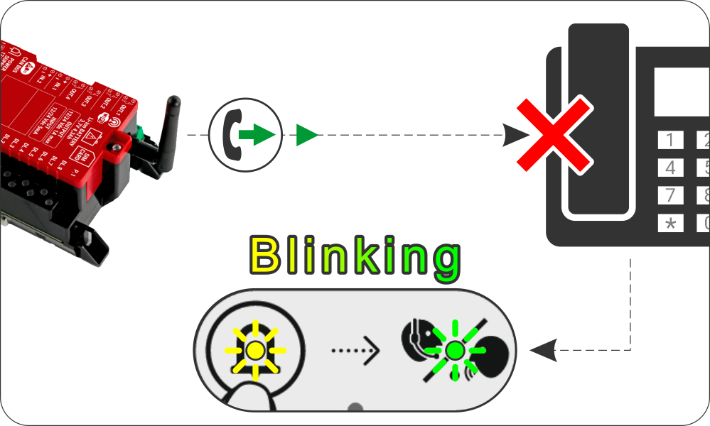 | If the automatic call fails, the “alarm sent” and “communication established” indicators will flash at one-second intervals. They will turn off after a successful automatic call. |
Audio Device Disconnected Call
If any audio device connected to the 2-wire Bus is disconnected, the system automatically sends a service call to the registered number, indicating the disconnection.
The call can be made in voice or data mode, depending on the configured protocol.
External Power Failure Call
f external power is lost, the system automatically sends a service call to the registered number, reporting the power failure on the device.
The call can be made in voice or data mode, depending on the configured protocol.
End Alarm Call (EN81-28)
After a manual alarm reset, the system automatically sends a call to the registered emergency number, indicating that the alarm has been reset locally.
The call can be made in voice or data mode, depending on the configured protocol.
Troubleshooting
Please refer first to the relevant section.
Datasheet
| Telephone dialer / router | |
|---|---|
| Voltage | 24 Vdc for more than 6 active audio devices |
| Max absorption | 20 W |
| Backup battery | Litium Battery 3.7V 4.3Ah |
| Backup battery autonomy | Note: The 120-minute autonomy is calculated considering a maximum configuration of 6 active audio devices + 2 passive audio devices. For configurations with a higher number of devices, an external backup power supply is required. |
| Digital BUS | 2 |
| Total power supplied by the two BUS | 16W |
| Operating temperature | -5°c ~ +50°c |
| MOBILE | |
| Band | • GSM 900: operating frequency 880–915 MHz (uplink) / 925–960 MHz (downlink), maximum output power 33 dBm • GSM 1800: operating frequency 1710–1785 MHz (uplink) / 1805–1880 MHz (downlink), maximum output power 30 dBm • 4G / LTE-FDD: supported bands B1 / B3 / B7 / B8 / B20 / B28A, maximum output power 23 dBm |
| LTE category | Cat1 (Voce) Cat4 (Multimedia) |
| WIRELESS LAN | |
| Bands | 2.4G |
| Mode | IEEE 802.11b/g/n, Access Point (AP) |
| AP (Max. Access Points) | 16 |
| Security Encryption Mode | WEP/ TKIP/ AES/ WPA-PSK/ WPA2-PSK |
| Data Rates | 802.11b 11 Mbps 802.11g 54 Mbps 802.11n 150 Mbps |
| Audio device | |
|---|---|
| Voltage | 12/24V DC |
| Max absorption | 50 mA (12V) 25 mA (24V) |
| Protection Class | IP54 |
Simplified EU Declaration of conformity
The manufacturer, DMG S.p.A., declares that the radio equipment type AMIGO ETSA3MRA (EMEA version) & ETSA3MRA.AU (Australian version) is in compliance with Directive 2014/53/EU – RED.
The full text of the EU Declaration of Conformity is available at the following Internet address:
https://dido.dmg.it/knowledge-base/declaration-of-conformity/#electronic-devices
Download
| Reference | Version | Link |
|---|---|---|
| 1.0 | Download PDF (English) | |
| Connection details for the Pitagora 4.0 | 1.2 | Download PDF (English) |
| Added intercom-only configuration | 1.3 | Download PDF (English) |