
Introduction
The TOC Pitagora is a metal box located on the top of the elevator cabin. It is part of the serial pre-wiring system and is used for the cabin connections, both internal and external. Inside the TOC box, some electronic boards, a terminal block, and any optional accessories are located.
General layout

A) Electronic board for decoding all signals present on the top of cabin (counting, inspection, door controls, etc.). Also includes the WiFi module for interaction with smartphones (Fusion App).
B) Terminal block for connecting the safety chain and high voltage signals (socket, door operator power supplies, cabin light, and retiring cam power supply).
C) LUPA board for connecting the cabin lighting and the retiring cam.
D) Optional boards:
- AUTO board for managing regulated door operators.
- MOT3 board for managing three-phase doors.
- 16RL board (relay board) for interfacing with existing devices (e.g., 1-wire display per segment).
- 16IO board (In / Out board)
Mounting
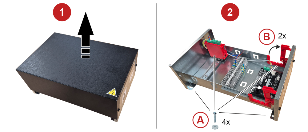
1) Remove the TOC box cover.
2A) Fix the TOC box to the top of cabin using the supplied screws.
2B) Pass the flat cable from the controller through the prepared cable glands.
Reassemble the TOC box cover.
Connecting the TOC box to the controller
All signals between the top of cabin and the controller are transmitted through the use of a single flat cable, which connects partly to the TOC electronic board (low voltage signals and communication lines) and partly directly to the terminal block (high voltage power supplies and safety chain).

A) Power supply for:
- Doors
- Retiring cam
- Cabin light
- Top of cabin socket
B) Control logic for:
- Telephony
- Intercom system.
C) Control logic for:
- Serial line
- Maintenance signal
- 24V power supply
- Door zone
D) Varios signals
E) Safety circuit:
- Doors
- Safety gear
- Emergency Stop command
- Balustrade
- Retractable apron
SPARE: Free cable for various uses.
Connecting the inspection box

Connections on the safety chains
The contacts of the safety chain are all NC (normally closed) type.

A) Cabin door contact:
- A1) Single access (CPCA): S37-S38
- A2) Double access: Door A (CPCA) S37-S39 / Door B (CPCB) S38-S39
B) Balustrade contact:
- Normal (BAN): S22-S31
- Inspection (BAR): S24-S30
C) Final limit switch contact (HCS): S36-S40
D) Safety gear contact (PAR): S35-S40
E) 2nd STOP contact (STOP): S32-S33
Connecting the inspection limit switch
Three types of connections are provided.
Limit switches not present
For example, in the case of using the ELGO LIMAX 33CP absolute encoder, the limit switches are managed by the encoder itself.
The following bridges between terminals should be provided:

Limit switches with contacts in the shaft
The contacts are in the shaft (see the safety chain), therefore the following bridges between terminals should be provided:

Limit switches with contacts on the top of cabin
The inspection limit switches are present on the top of cabin and are connected to the terminal block in the toc box as shown in the images below.
Inspection limit switch on the top of cabin

Inspection limit switch at the pit bottom

Not required in the case of EN81-21 standard.
Accessories

A) Load weighing device contact (M12)
B) Visual signals EN81-21 (Traffic Light): Reduced headroom (J7A) / Reduced Pit (J7B)
C) Acoustic signal EN81-20 (Buzzer J6)
D) Siren connection (M11). It is possible to connect the siren directly to the controller by first removing the connector.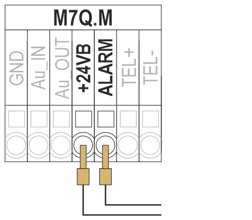
E) Emergency light
F) LUPA electronic board – Retiring cam control (MCAMOUT)
G) LUPA electronic board – Cabin light
- Fixed light (MLOUT)
- Timed light (MLTMPOUT)