(v 1.0)

Giotto + MosaicONE
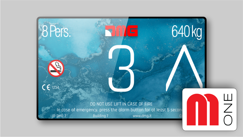
Giotto is DMG’s 65,000 color TFT display, now available with various graphic templates that can be customized directly from the MosaicONE platform.
Its various sizes can cover multiple widths of fixtures:
Giotto 4,3″
Giotto 5″
Giotto 5,6″
Giotto 7″
Giotto 10,1″
General system layout
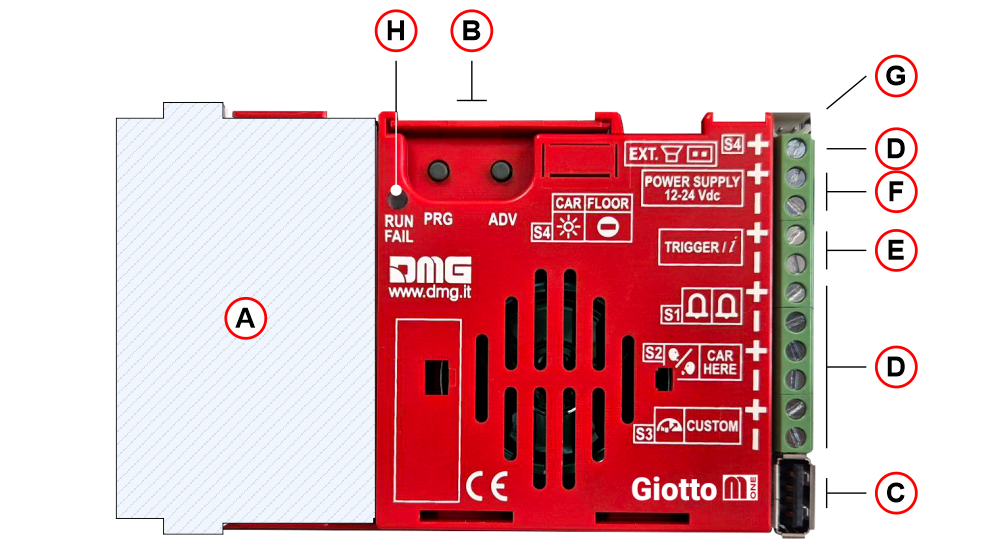
| ( A ) | Slot for DMG interface cards | |
| ( B ) | Programming keys | |
| ( C ) | USB plug | |
| ( D ) | Signal inputs | |
| ( E ) | Sound trigger input | |
| ( F ) | Power Supply (12/24 Vdc) | |
| ( G ) | Audio OUT (External speakers) | |
| ( H ) | Diagnostic Led |
Mounting
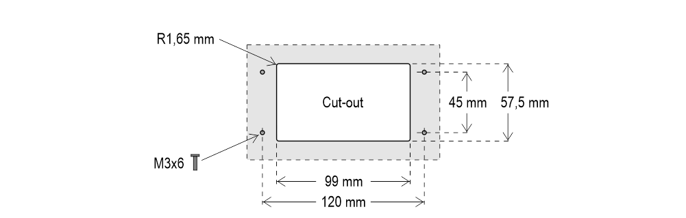
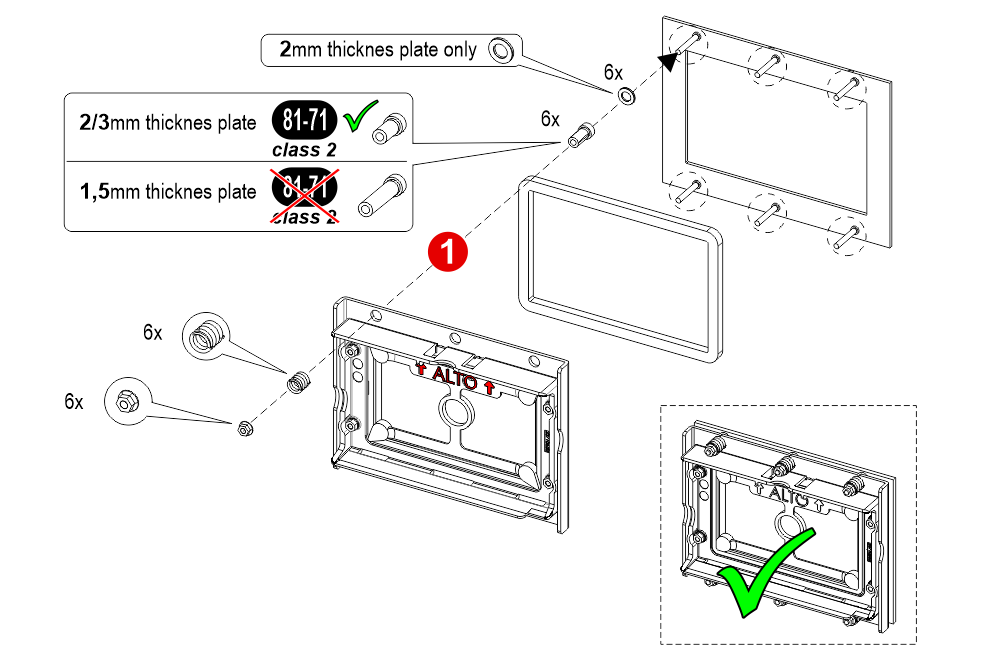
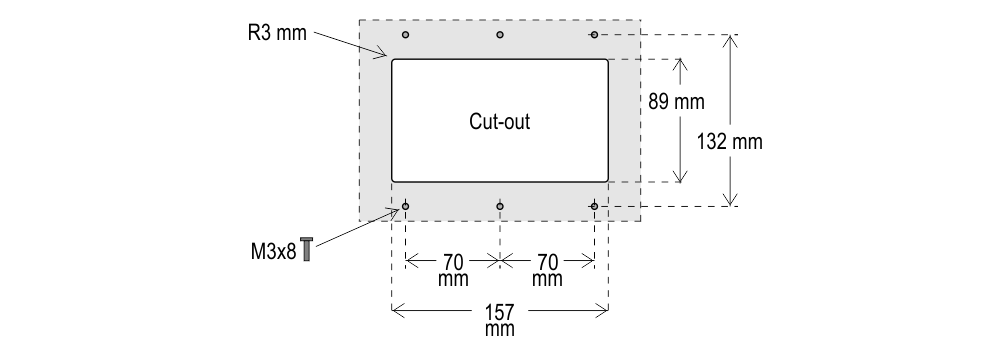
Giotto 4.3″
With welded pins on 1,5/3 mm pushbutton panel


 If you are replacing an existing position indicator, please verify that studs’ length match the above mentioned one; if not, please shorten them.
If you are replacing an existing position indicator, please verify that studs’ length match the above mentioned one; if not, please shorten them.Giotto 4.3″ (EN81-71)
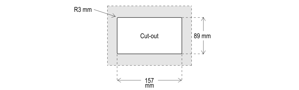
With welded pins on 2/3 mm pushbutton panel

 If you are replacing an existing position indicator, please verify that studs’ length match the above mentioned one; if not, please shorten them.
If you are replacing an existing position indicator, please verify that studs’ length match the above mentioned one; if not, please shorten them.Giotto 5″
With pins on backplate (for 1/1,5 mm pushbutton panel)
 With welded pins on 2/3 mm pushbutton panel
 Frontal mounted on 1/2 mm pushbutton panel
With welded pins on 2/3 mm pushbutton panelFrontal mounted on 1/2 mm pushbutton panelGiotto 5.6″
With welded pins on 1,5/3 mm pushbutton panel
 If you are replacing an existing position indicator, please verify that studs’ length match the above mentioned one; if not, please shorten them.
If you are replacing an existing position indicator, please verify that studs’ length match the above mentioned one; if not, please shorten them.Giotto 7″
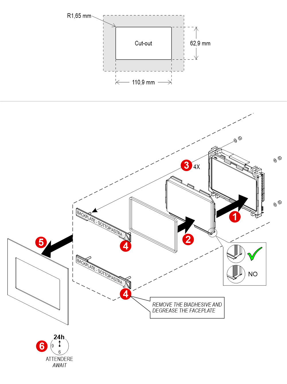
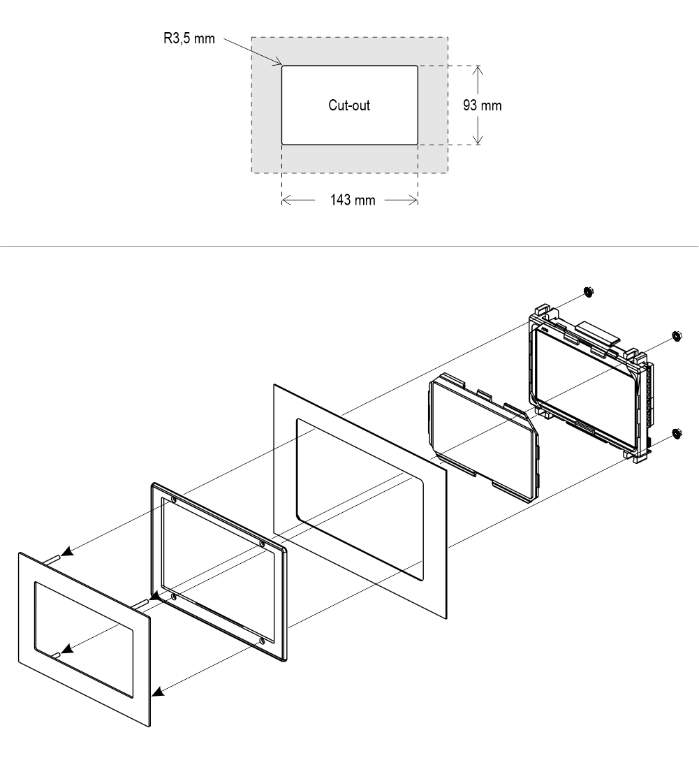
With welded pins on 1,5/3 mm pushbutton panel
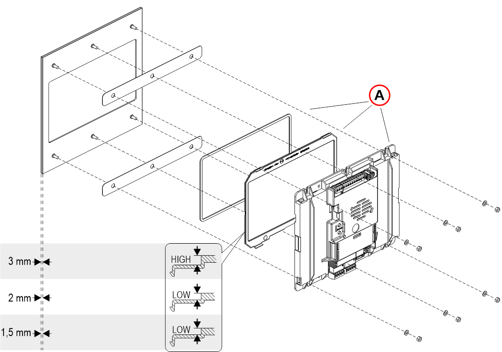
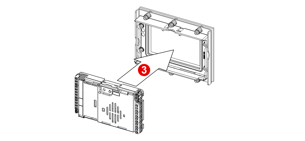
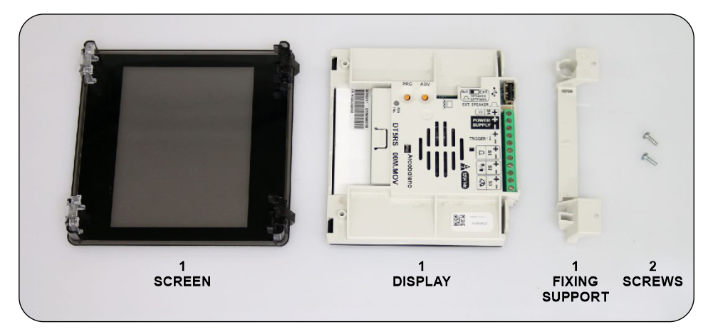
A) – These 3 components may have already been assembled in DMG.
With pins on backplate (for 1/2 mm pushbutton panel)
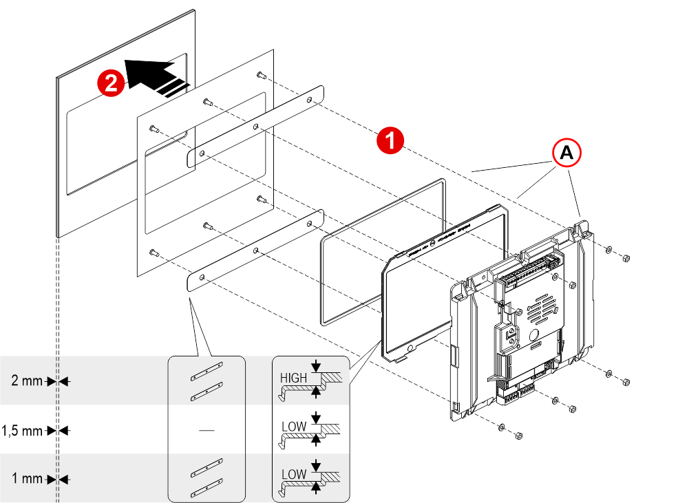
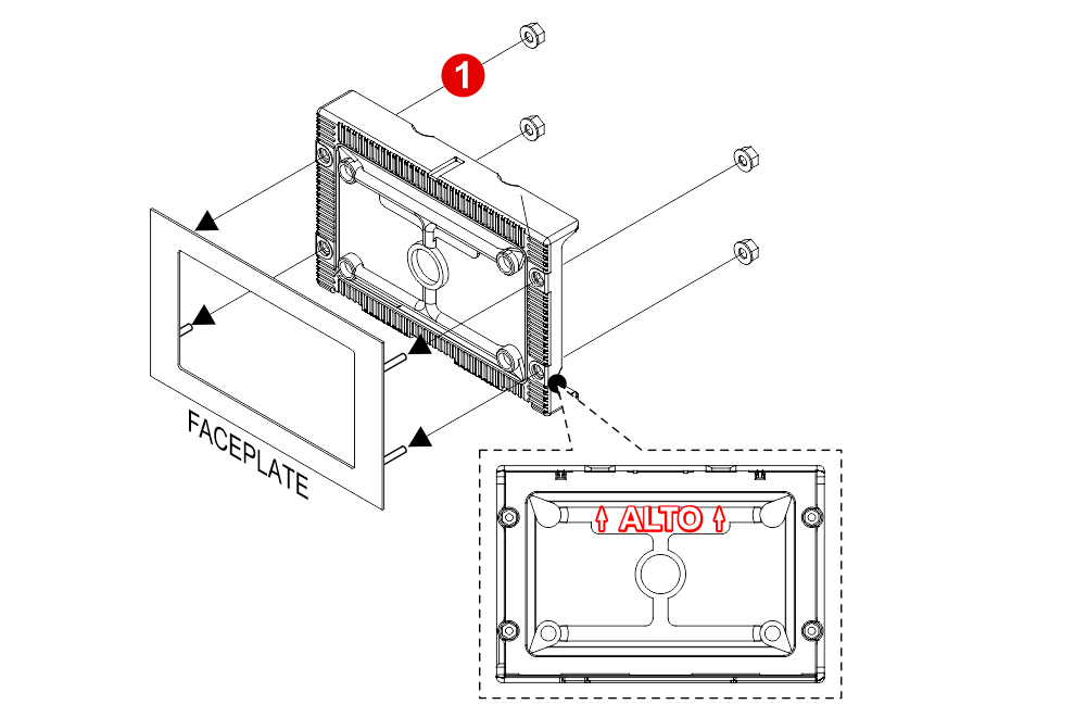
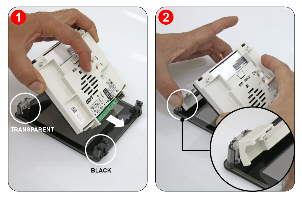
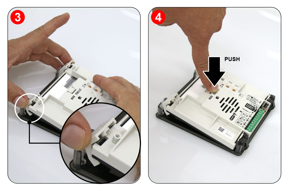
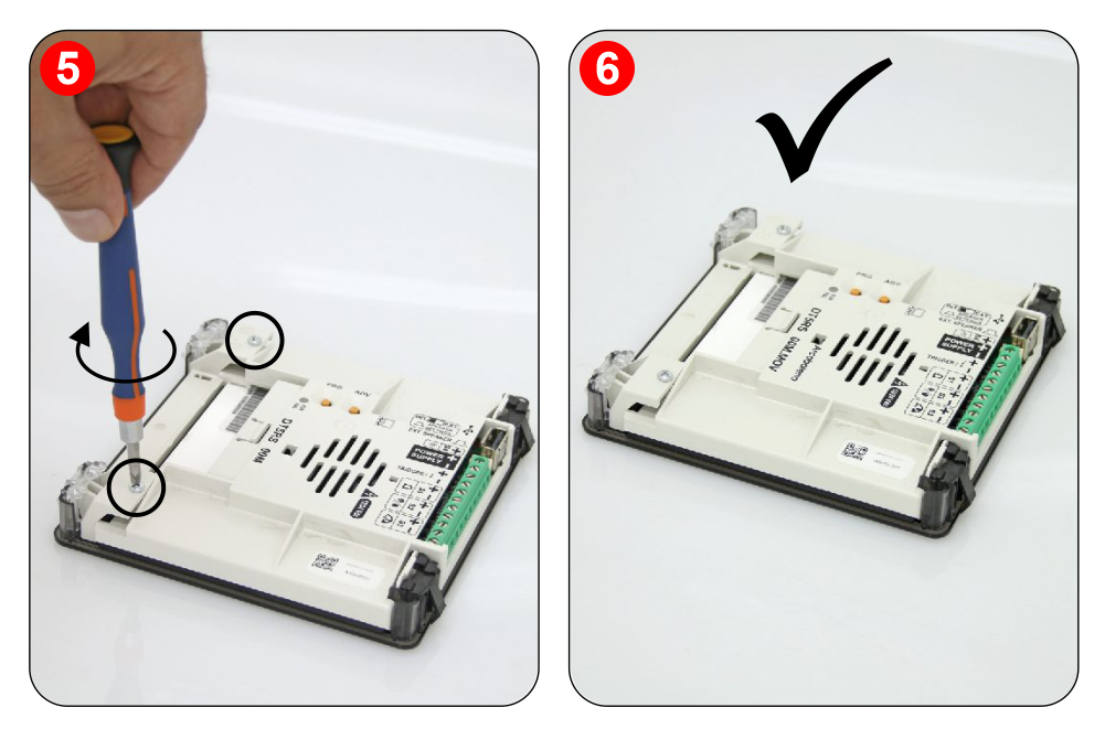
1) – Assemble all the components.
2) – First of all remember to remove the double-sided tape from the subplate.
A) – These 3 components may have already been assembled in DMG.
A) – These 3 components may have already been assembled in DMG.
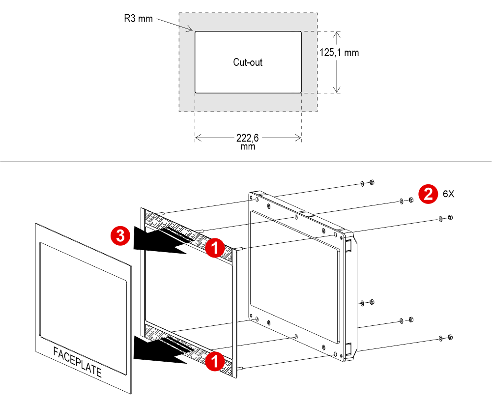
With pins on backplate (for 1/2 mm pushbutton panel)
1) – Assemble all the components.
2) – First of all remember to remove the double-sided tape from the subplate.
A) – These 3 components may have already been assembled in DMG.
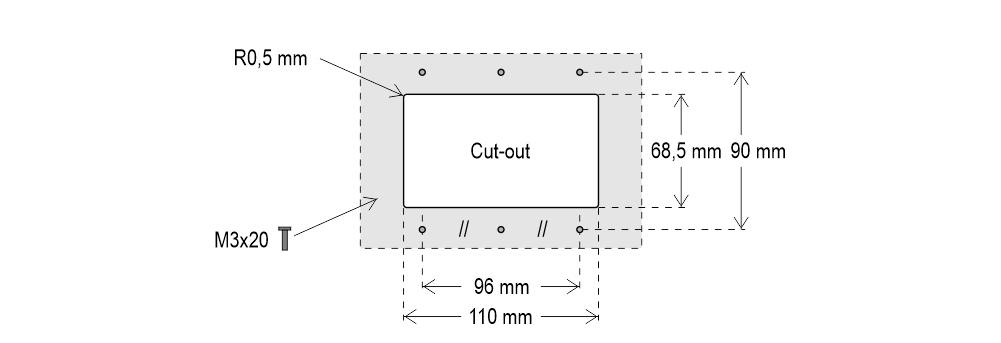
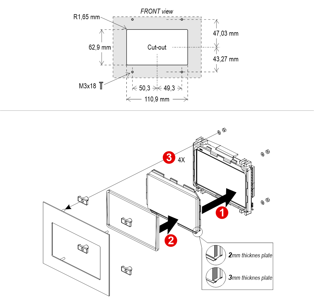
Giotto 7″ (EN81-71)
With welded pins on 2/3 mm pushbutton panel
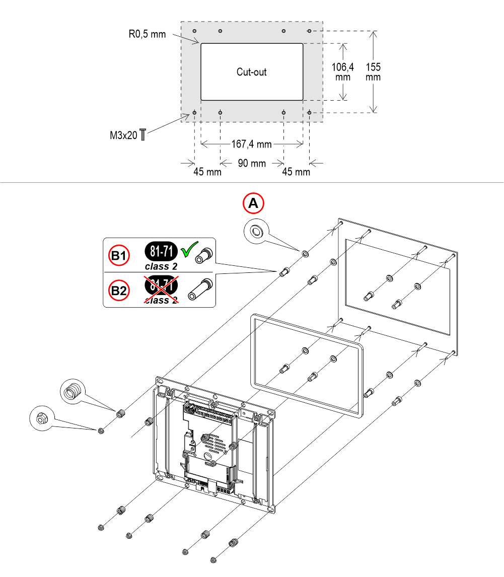
A) – With 2mm thickness plate only
B1) – With 2/3mm thickness plate
B2) – With 1,5mm thickness plate (NOT EN81-71)
If you are replacing an existing position indicator, please verify that studs’ length match the above mentioned one; if not, please shorten them.
A) – With 2mm thickness plate only
B1) – With 2/3mm thickness plate
B2) – With 1,5mm thickness plate (NOT EN81-71)
If you are replacing an existing position indicator, please verify that studs’ length match the above mentioned one; if not, please shorten them.Giotto 10.1″
Giotto 10,1″ overall dimensions: 243 x 169 mm (h 35,5 mm)
With welded pins on 1,5/3 mm pushbutton panel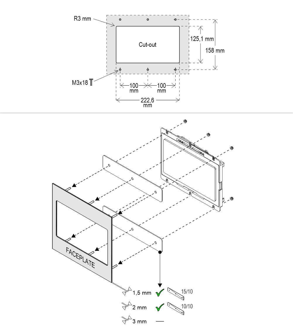
With pins on backplate (for 1,5/2 mm pushbutton panel)
1) Remove the double-sided tape
With welded pins on 1,5/3 mm pushbutton panel
With pins on backplate (for 1,5/2 mm pushbutton panel)
1) Remove the double-sided tape
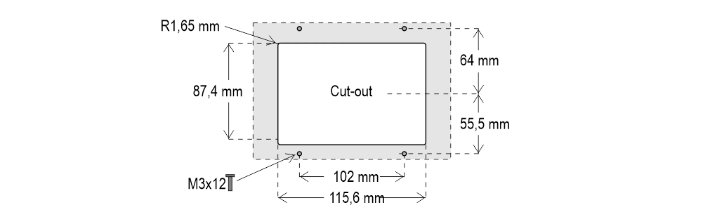
Giotto Retrofit
Frontal mounted version for retrofitting, same cut-out of D67 position indicator.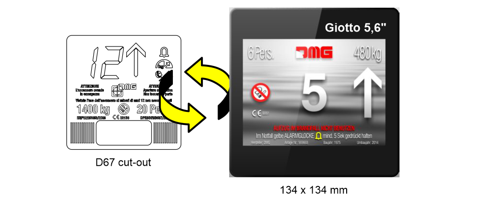
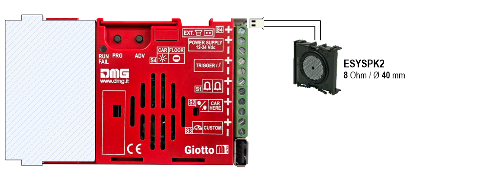
ESYSPK2 external speaker (option)
Back view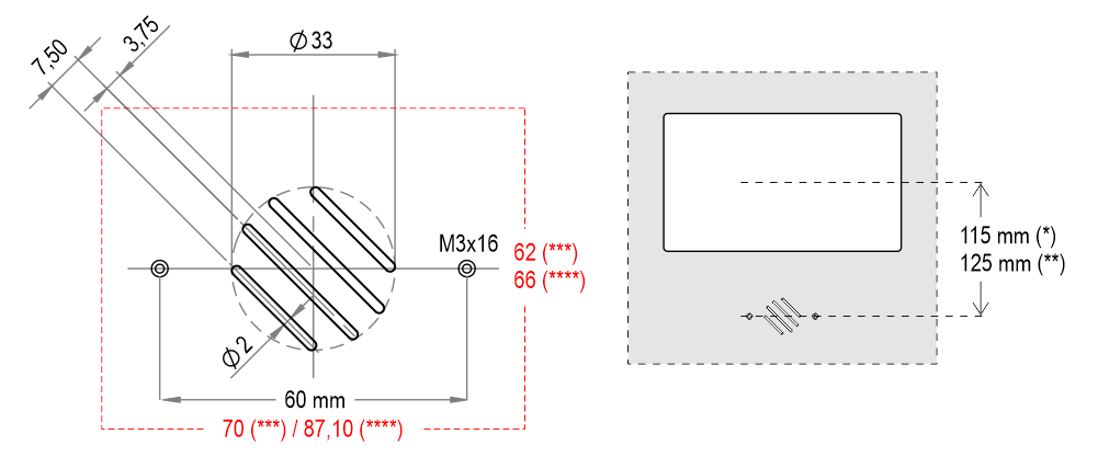 (*) – TFT Up to 7″
(**) – TFT 10,1″
(***) – Version with welded pins
(****) – Version with backplate and biadhesive
(*) – TFT Up to 7″(**) – TFT 10,1″
(***) – Version with welded pins
(****) – Version with backplate and biadhesive
Wiring
Basic Wiring
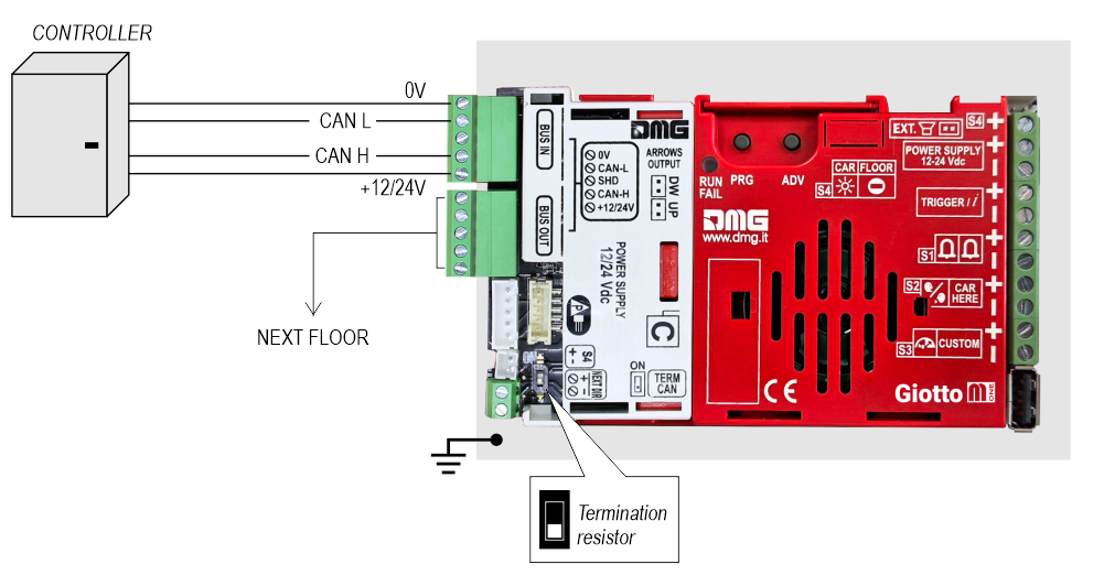
Giotto + NON-DMG Controllers
Proprietary CAN protocol
1 Wire / Floor
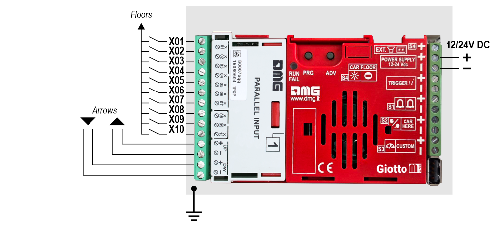 10 floors max.
1 Wire / Segment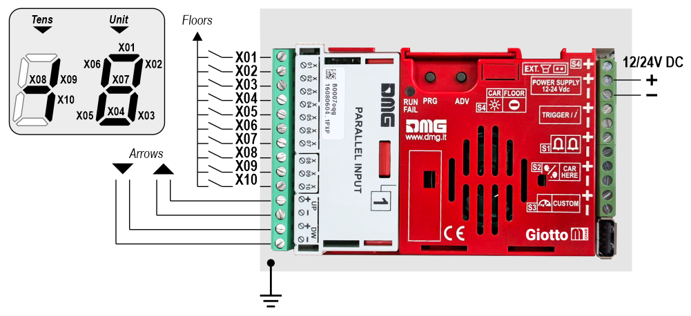 29 floors max. (-9, 0, 19)
Gray / Binary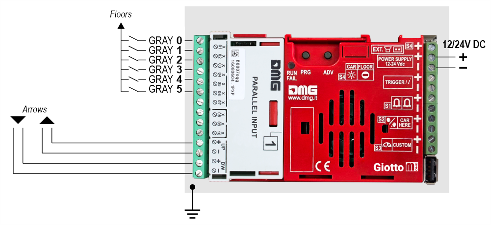 72 floors max. (-9, 0, 62)
TKE/MEA/Autinor
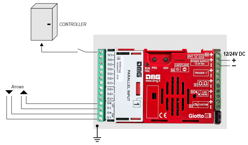
Indipendent sensor
With this connection, the following settings are required in the programming menu:
Giotto M1 / Input
• Pos. Sensor (Manual) – The arrows are controlled by inputs
• Pos. Sensor (Auto) – The arrows are controlled by sensors
Giotto M1 / Options / Interface options / Display configuration
• COP (Car operating panel display)
Giotto M1 / Options / Interface options / Common selections
• Negative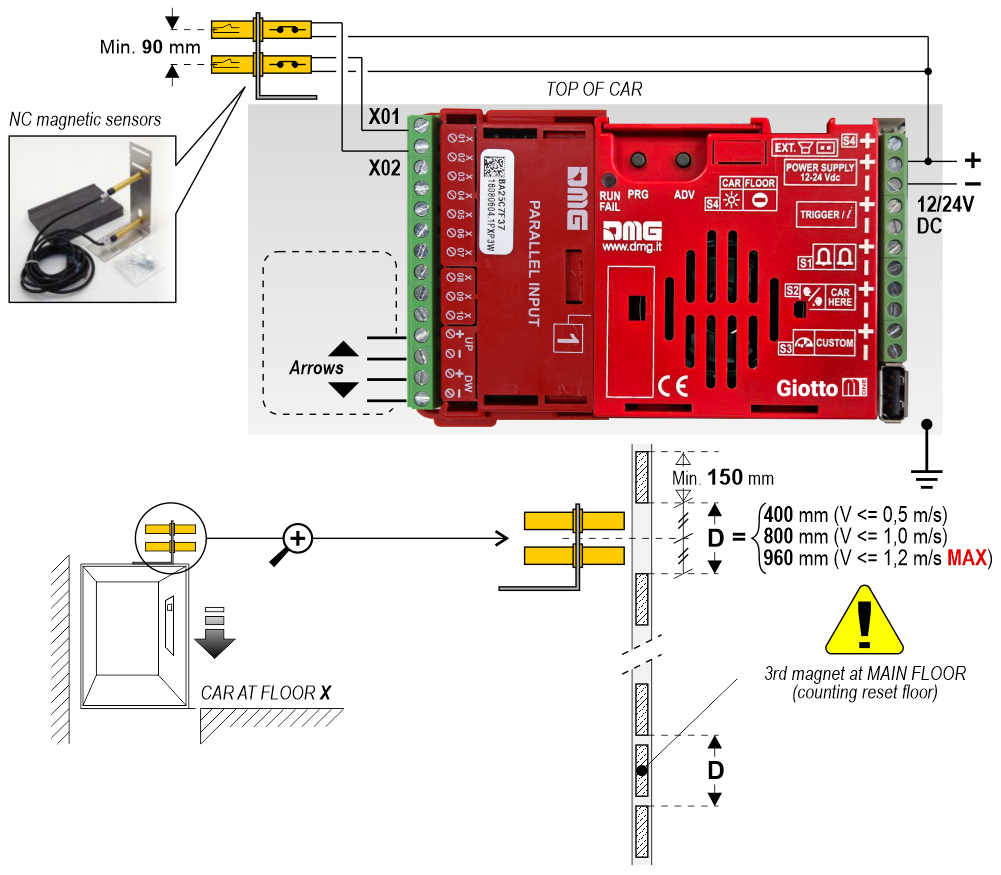
1 Wire / Floor
10 floors max.1 Wire / Segment
29 floors max. (-9, 0, 19)Gray / Binary
72 floors max. (-9, 0, 62)TKE/MEA/Autinor
Indipendent sensor
With this connection, the following settings are required in the programming menu:
Giotto M1 / Input
• Pos. Sensor (Manual) – The arrows are controlled by inputs
• Pos. Sensor (Auto) – The arrows are controlled by sensors
Giotto M1 / Options / Interface options / Display configuration
• COP (Car operating panel display)
Giotto M1 / Options / Interface options / Common selections
• Negative
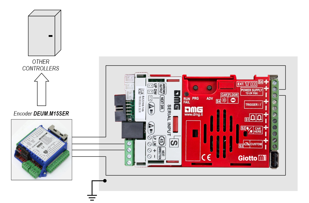
Giotto + DEUM Encoder
 For more details please refer to the Encoder DEUM support page
DMG CAN serial protocol
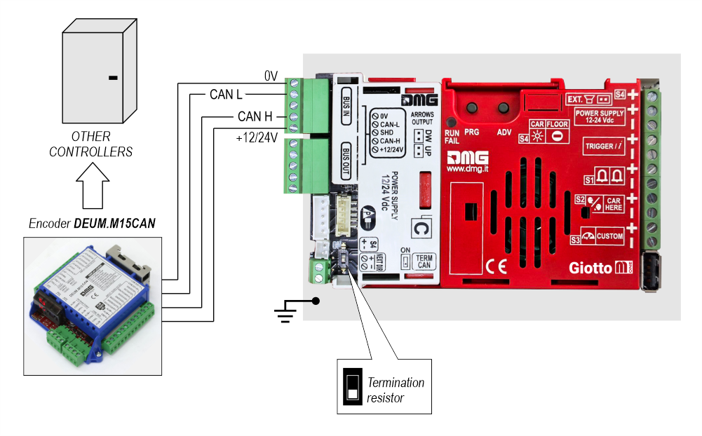
DMG 3-wires serial protocol
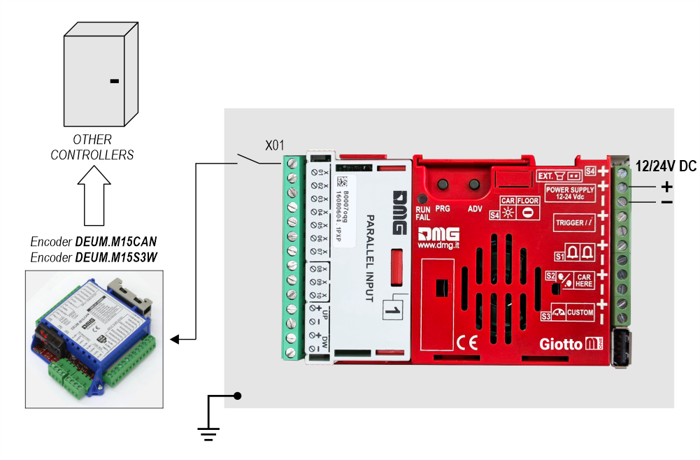
RS485 serial
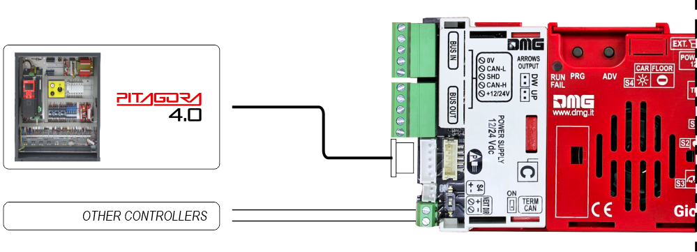
Giotto + Pitagora 4.0
CAR
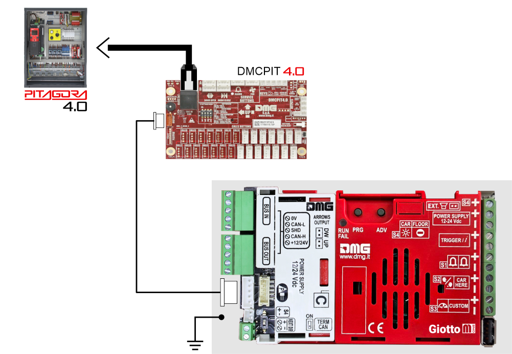
FLOOR
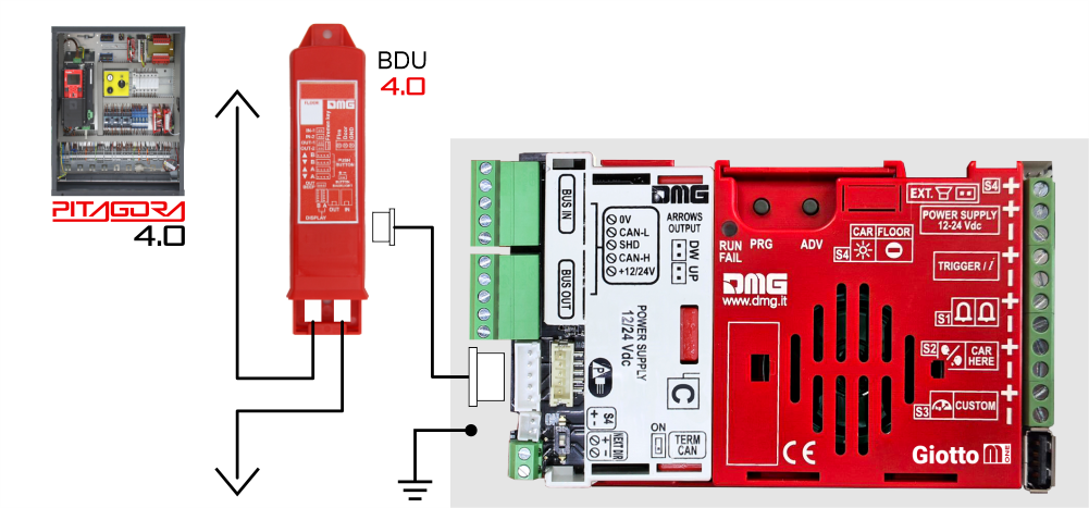
FLOOR
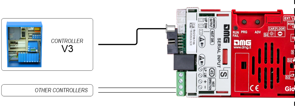
Giotto + Pitagora V3
CAR
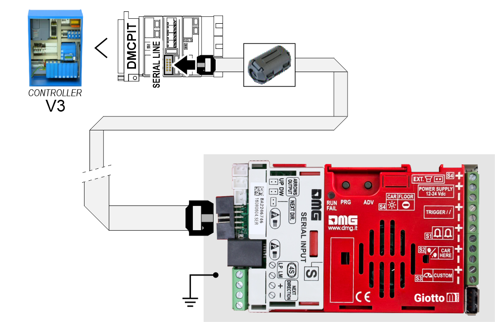
FLOOR
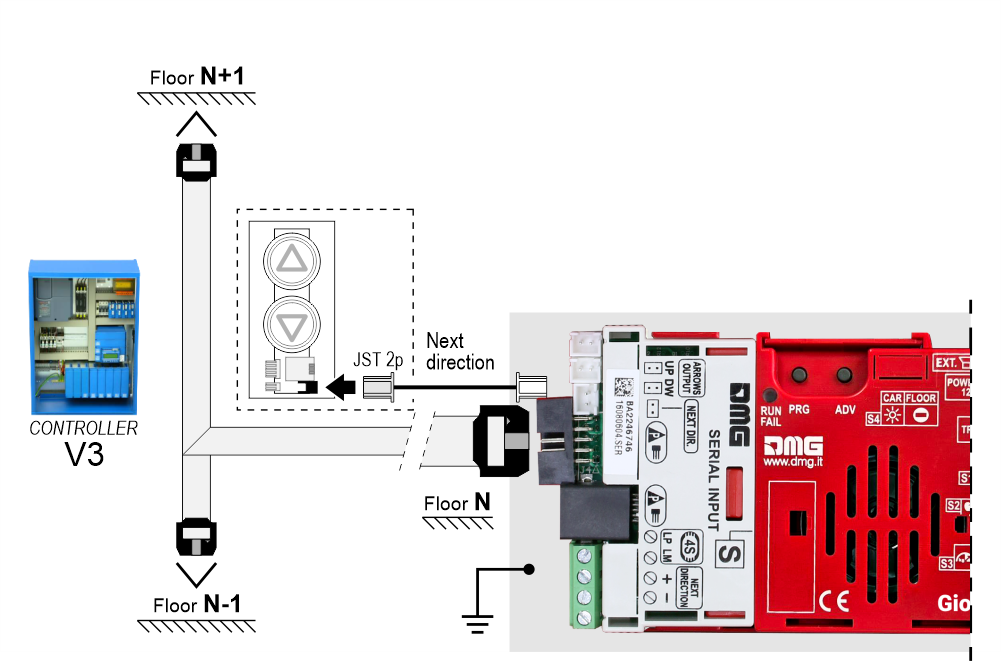
FLOOR
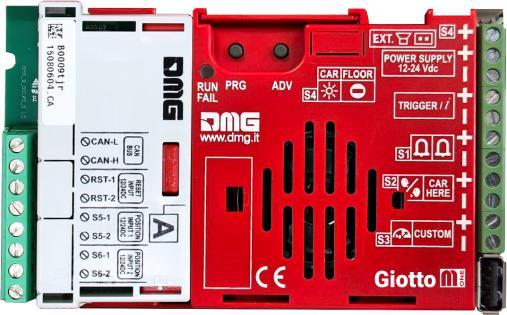
Giotto + A.P.S. (Autonomous Positioning System)
The Autonomous Positioning System for the DMG displays of the Raffaello, Giotto and Matisse series, allows to show the lift position and direction independently from the controller. The interface uses the sensors signals installed on the top of elevator car.
If available, it is possible to use the same position sensors used by the controller.
If NOT availale, you have to install:
• 1 NO magnetic sensor on the cabin + 1 magnet at every floors for counting position.
• 1 NO magnetic sensor on the cabin + 1 magnet at main floor for the RESET.
In this interface there is a CAN BUS serial line for piloting the position indicators of floor.
For all other functions (Voice Synthesizer, gong, indicators, etc.) please refer to the display technical support page.
Autonomous positioning System
Giotto + CANopen protocol
The TFT CANopen interface is a device for interfacing DMG displays to all third-party CANopen controllers on the market.
The DMG displays of the CANopen line comply with the standards CiA-301 and CiA-417 (Lift).
The elevator functions described by the CiA-417 profile and implemented in the displays are:
1) Position
2) Arrows
3) Trigger
4) Signalisations
5) Gong
6) Lift data
The image below shows the connection principle of a CANopen DMG display.
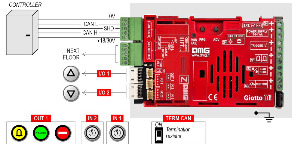
I/O 1/2, OUT 1, IN 1-2 : This is just an example of how to connect the inputs/outputs of the CANopen interface.
The DMG CANopen displays have new menu parameters through which the installer user can set:
The CANopen node ID (“NodeID”)
The baud rate of the CAN line (“Baud rate”)
Service messages wiring
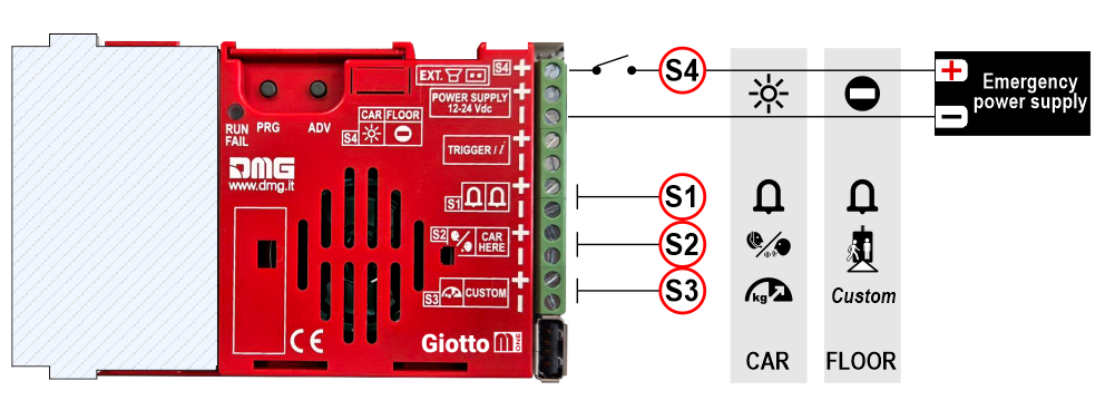
| CAR | FLOOR | |
|---|---|---|
| S1 | Alarm sent | Alarm |
| S2 | Communication establiched | Car here |
| S3 | Overload | Custom |
| S4 | Antipanic light | No entry |
TRIGGER command wiring (parallel inputs only)
This input must be used to trigger floor-related voice messages and gong.
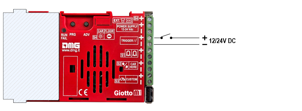
No polarity
Connecting external accessories
Connecting an external speaker
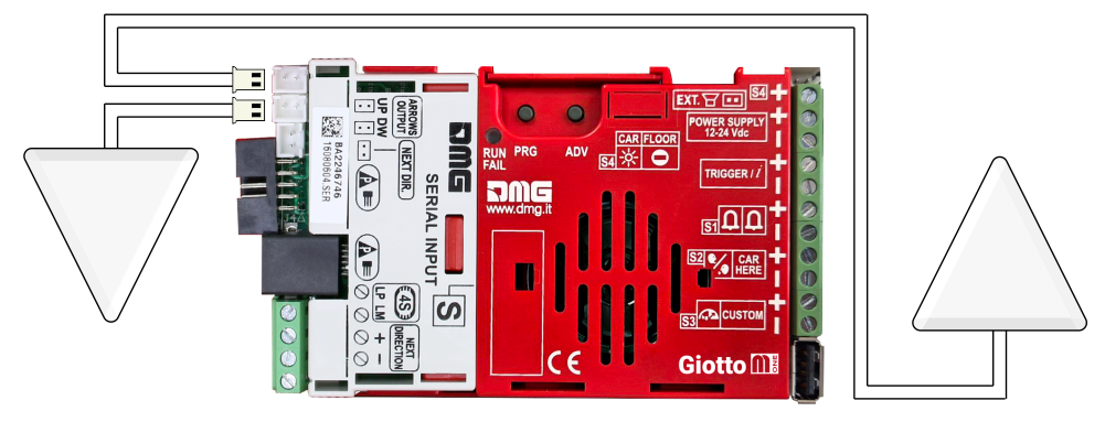
Connecting an external arrows
Setting on-board parameters
All the Giotto visual setups can be viewed and modified using Mosaic One. Some parameters are only available in the on-board menu:
Navigating the on-board Menu
| PRG | ADV | |
 | Access key to: menu, submenu, settings Value setting | Menu navigation key |
Press PRG to enter the menu.
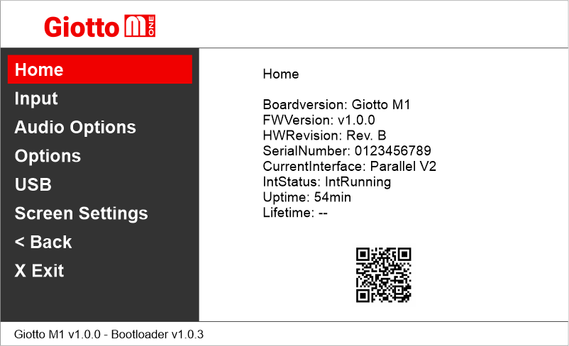
The QR code shown on the home screen refers to the DIDO web page of the Giotto M-One
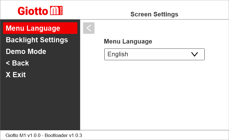
Setting the menu navigation language
Giotto M1 >> Screen Settings >> Menu Language
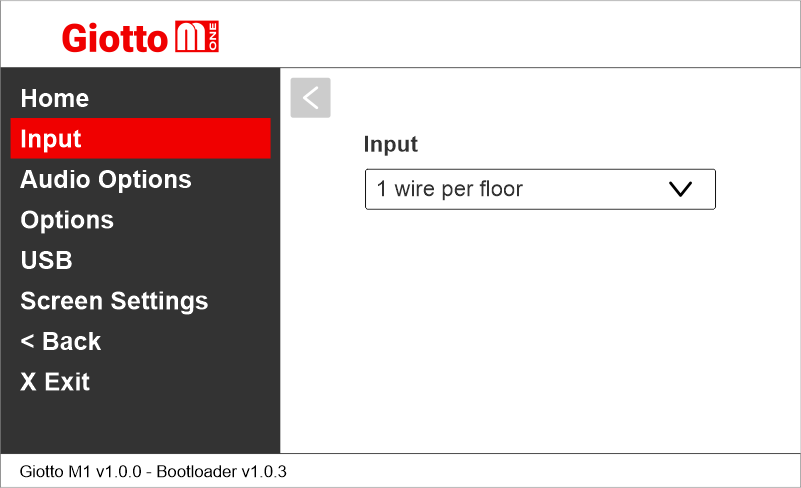
Setting the encoding protocol
Giotto M1 >> Input
The parameters change according to the connected interface.
Setting the interface options
Giotto M1 >> Options >> Interface Options
Parallel interface
Setting Giotto as elevator car indicator or floor indicator
Giotto M1 >> Options >> Interface Options >> Display Configuration
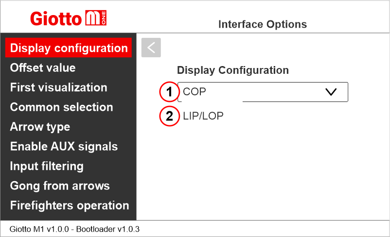
Set whether it is a car display (COP) or a landing display (LIP/LOP)
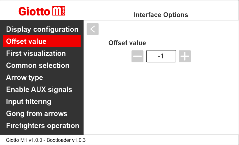
Setting the floor offset
Giotto M1 >> Options >> Interface Options >> Offset
Setting the first visualization
Giotto M1 >> Options >> Interface Options >> First visualization
This parameter is used with binary or Gray input and determines the display’s behavior when all the inputs are inactive (corresponding to the controller setting all bits to “0”)
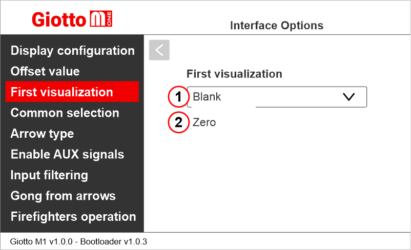
1) It does not display any numbers
2) Lowest floor
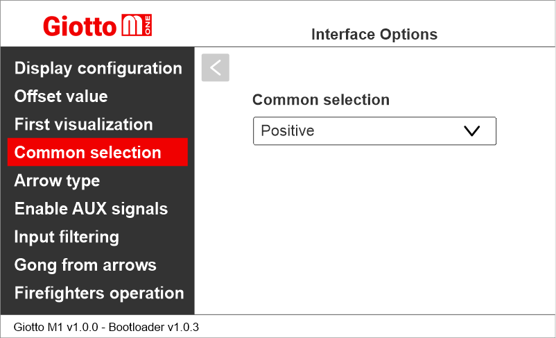
Setting the common of the parallel position inputs
Giotto M1 >> Options >> Interface Options >> Common selection
Setting the scrolling arrows
Giotto M1 >> Options >> Interface Options >> Arrow type
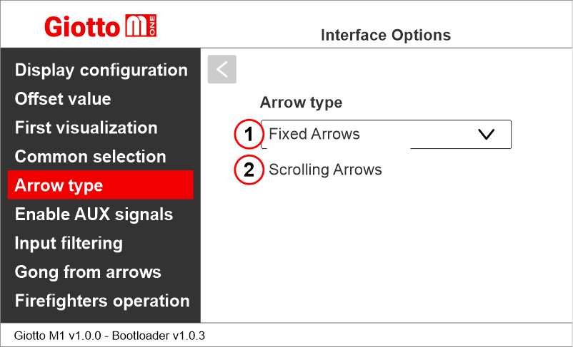
1) Fixed arrows
2) Scrolling arrows
Enabling of auxiliary signals
Giotto M1 >> Options >> Interface Options >> Enable AUX Signals
When the parameter “Enable AUX signals” is set to “6+4”, you can assign service message symbols to AUX inputs (X07 to X10) using this menu.
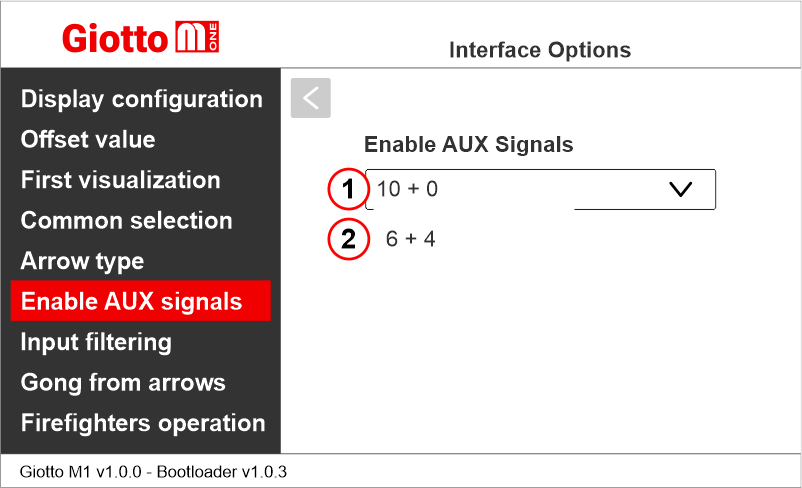
1) 10 Floor parallel inputs (X01÷X10) + 0 AUX Signals
2) 6 Floor parallel inputs (X01÷X06) + 4 AUX Signals (X07÷X10)
Setting the display delay of floor change
Giotto M1 >> Options >> Interface Options >> Input filtering
The display delay helps avoiding visualization errors during floor change.
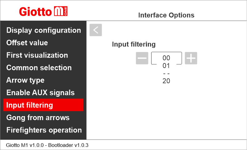
00 = disabled
01 = 100 ms
—
20 = 2000 ms
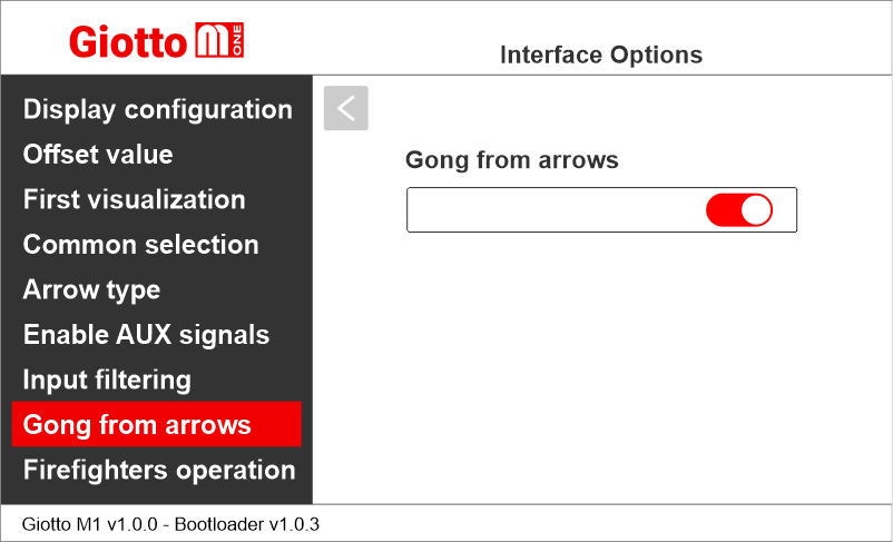
Enabling Gong from arrow input
Giotto M1 >> Options >> Interface Options >> Gong from arrows
This option allows to use the arrow input as trigger for audio message playback.
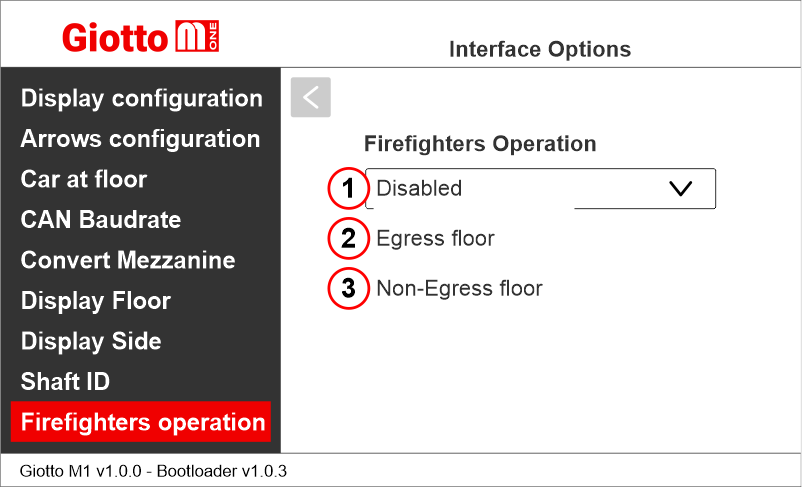
Enabling the Firefighters Operation parameter
Giotto M1 >> Options >> Interface Options >> Firefighters operation
This parameter allows to set the display during the firefighters operation.
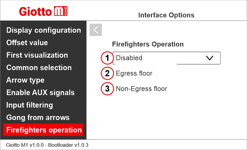
1) Disabled: normal operation
2) Egress Floor: when in firefighters operation, the indicator only shows the floor symbols.
3) Non-Egress Floor: when in firefighters operation, the indicator blacks out.
Giotto M1 >> Options >> Interface Options >> Display Configuration
Set whether it is a car display (COP) or a landing display (LIP/LOP)
Setting the floor offset
Giotto M1 >> Options >> Interface Options >> Offset
Setting the first visualization
Giotto M1 >> Options >> Interface Options >> First visualization
This parameter is used with binary or Gray input and determines the display’s behavior when all the inputs are inactive (corresponding to the controller setting all bits to “0”)
1) It does not display any numbers
2) Lowest floor
Setting the common of the parallel position inputs
Giotto M1 >> Options >> Interface Options >> Common selection
Setting the scrolling arrows
Giotto M1 >> Options >> Interface Options >> Arrow type
1) Fixed arrows
2) Scrolling arrows
Enabling of auxiliary signals
Giotto M1 >> Options >> Interface Options >> Enable AUX Signals
When the parameter “Enable AUX signals” is set to “6+4”, you can assign service message symbols to AUX inputs (X07 to X10) using this menu.
1) 10 Floor parallel inputs (X01÷X10) + 0 AUX Signals
2) 6 Floor parallel inputs (X01÷X06) + 4 AUX Signals (X07÷X10)
Setting the display delay of floor change
Giotto M1 >> Options >> Interface Options >> Input filtering
The display delay helps avoiding visualization errors during floor change.
00 = disabled
01 = 100 ms
—
20 = 2000 ms
Enabling Gong from arrow input
Giotto M1 >> Options >> Interface Options >> Gong from arrows
This option allows to use the arrow input as trigger for audio message playback.
Enabling the Firefighters Operation parameter
Giotto M1 >> Options >> Interface Options >> Firefighters operation
This parameter allows to set the display during the firefighters operation.
1) Disabled: normal operation
2) Egress Floor: when in firefighters operation, the indicator only shows the floor symbols.
3) Non-Egress Floor: when in firefighters operation, the indicator blacks out.
Serial interfaces (CAN BUS / RS485)
Setting Giotto as elevator car indicator or floor indicator
Giotto M1 >> Options >> Interface Options >> Display Configuration
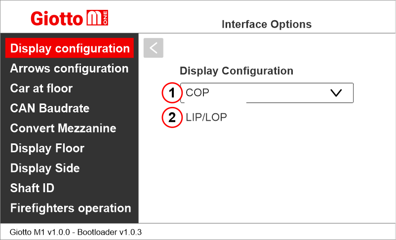
Set whether it is a car display (COP) or a landing display (LIP/LOP)
Setting the arrows configuration
Giotto M1 >> Options >> Interface Options >> Arrows configuration
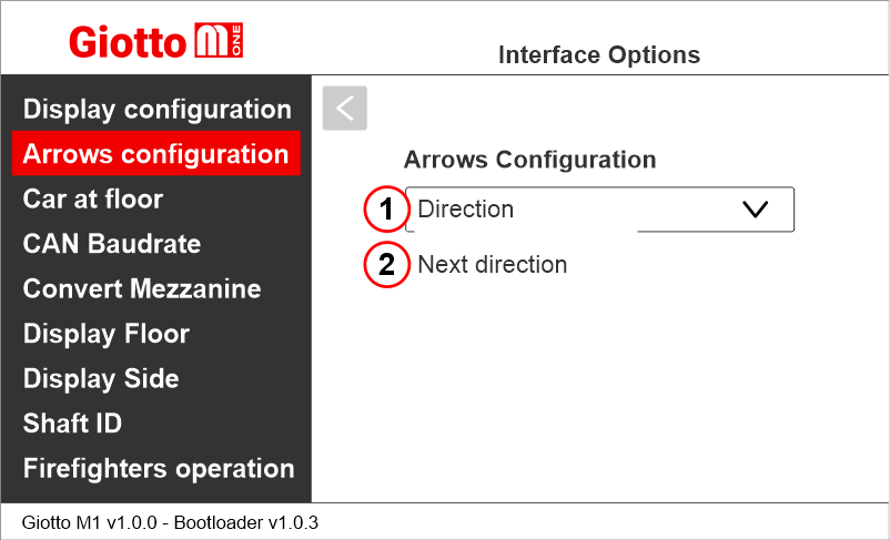
1) Direction arrows – only show the car current direction of travel.
2) Next direction arrows – show car next direction of travel after stop. (further information below)
Next Direction Arrows enabled from input
Gong and arrows light up only on the position indicators with the “NEXT DIRECTION” input powered.
– CAN serial interface
– RS485 serial interface
If the DEUM Encoder is used, please refer to the relevant manual
Next Direction Arrows locally programmed
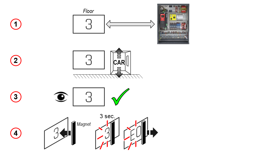
Through the addressing procedure one can permanently assign to each indicator the information of the floor on which it is mounted; in this way, next direction arrows only light up at the floor where the car is positioned.
– Addressing procedure –
1) – Connect all position indicators to the ENCODER or PLAYBOARD controller.
2) – Position elevator car on the floor of the Display which needs to be directed.
3) – Verify that the characters/numbers/letters visualized are the desired ones.
4) – Put a magnet in front of the indicator and wait for it to blink for 3 seconds for confirmation.
5) – Repeat procedure for each floor.
If the DEUM Encoder is used, please refer to the relevant manual
Enable signal of “Car at Floor” from “NEXT DIR.” input
Giotto M1 >> Options >> Interface Options >> Car at floor
This option allows to use the next direction input to light up “Car at floor” signal (if applicable).

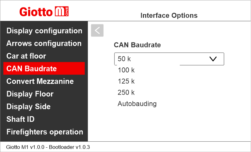
Setting CAN BUS protocol transmission speed
Giotto M1 >> Options >> Interface Options >> CAN Baudrate
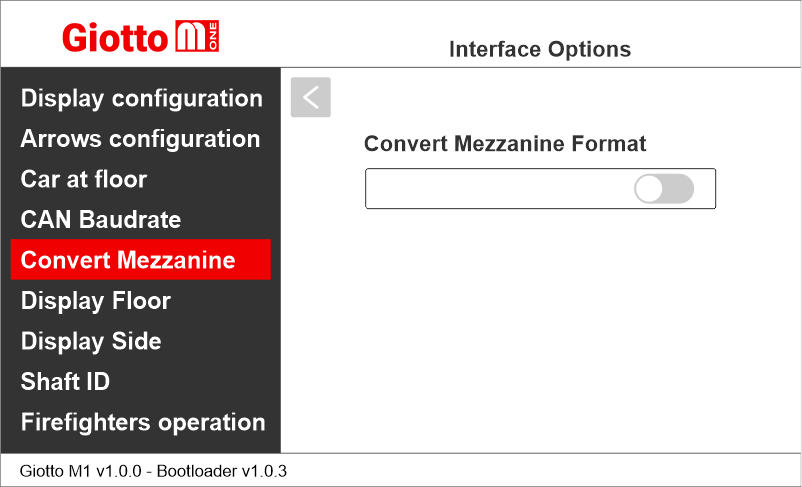
Setting the visualization of the intermediate floors
Giotto M1 >> Options >> Interface Options >> Convert Mezzanine
This option automatically converts intermediate floor signals into traditional “Mezzanine style” format (1/2, 2/3, etc.). Available only for floors 1 to 8.
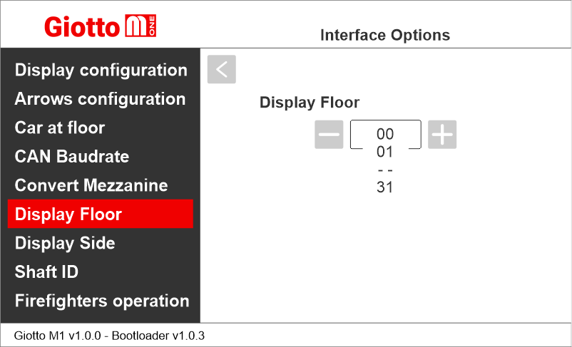
Display Floor
Giotto M1 >> Options >> Interface Options >> Display Floor
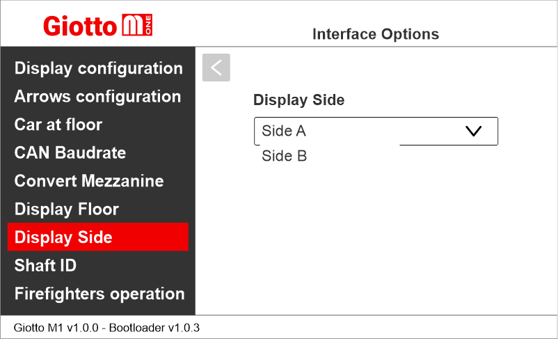
Display Side
Giotto M1 >> Options >> Interface Options >> Display Side
Associate the floor position indicator with the duplex controllers
Giotto M1 >> Options >> Interface Options >> Shaft ID
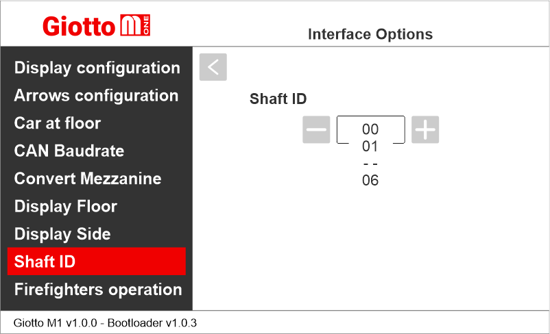
Select the ID of the elevator this indicators refers to.
0 for legacy, generic or car indicator.
1 to 6 for a specific elevator.
Enabling the Firefighters Operation parameter
Giotto M1 >> Options >> Interface Options >> Firefighters operation
This parameter allows to set the display during the firefighters operation.
1) Disabled: normal operation
2) Egress Floor: when in firefighters operation, the indicator only shows the floor symbols.
3) Non-Egress Floor: when in firefighters operation, the indicator blacks out.
Giotto M1 >> Options >> Interface Options >> Display Configuration
Set whether it is a car display (COP) or a landing display (LIP/LOP)
Setting the arrows configuration
Giotto M1 >> Options >> Interface Options >> Arrows configuration
1) Direction arrows – only show the car current direction of travel.
2) Next direction arrows – show car next direction of travel after stop. (further information below)
Next Direction Arrows enabled from input
Gong and arrows light up only on the position indicators with the “NEXT DIRECTION” input powered.
– CAN serial interface
– RS485 serial interface
If the DEUM Encoder is used, please refer to the relevant manual
Next Direction Arrows locally programmed
Through the addressing procedure one can permanently assign to each indicator the information of the floor on which it is mounted; in this way, next direction arrows only light up at the floor where the car is positioned.
– Addressing procedure –
1) – Connect all position indicators to the ENCODER or PLAYBOARD controller.
2) – Position elevator car on the floor of the Display which needs to be directed.
3) – Verify that the characters/numbers/letters visualized are the desired ones.
4) – Put a magnet in front of the indicator and wait for it to blink for 3 seconds for confirmation.
5) – Repeat procedure for each floor.
If the DEUM Encoder is used, please refer to the relevant manual
Enable signal of “Car at Floor” from “NEXT DIR.” input
Giotto M1 >> Options >> Interface Options >> Car at floor
This option allows to use the next direction input to light up “Car at floor” signal (if applicable).
Setting CAN BUS protocol transmission speed
Giotto M1 >> Options >> Interface Options >> CAN Baudrate
Setting the visualization of the intermediate floors
Giotto M1 >> Options >> Interface Options >> Convert Mezzanine
This option automatically converts intermediate floor signals into traditional “Mezzanine style” format (1/2, 2/3, etc.). Available only for floors 1 to 8.
Display Floor
Giotto M1 >> Options >> Interface Options >> Display Floor
Display Side
Giotto M1 >> Options >> Interface Options >> Display Side
Associate the floor position indicator with the duplex controllers
Giotto M1 >> Options >> Interface Options >> Shaft ID
Select the ID of the elevator this indicators refers to.
0 for legacy, generic or car indicator.
1 to 6 for a specific elevator.
Enabling the Firefighters Operation parameter
Giotto M1 >> Options >> Interface Options >> Firefighters operation
This parameter allows to set the display during the firefighters operation.
1) Disabled: normal operation
2) Egress Floor: when in firefighters operation, the indicator only shows the floor symbols.
3) Non-Egress Floor: when in firefighters operation, the indicator blacks out.
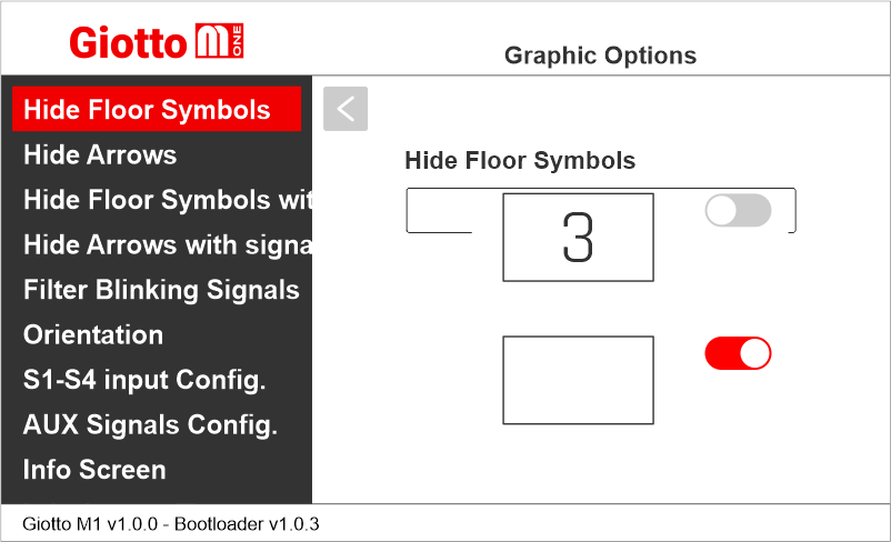
Setting the graphic options
Giotto M1 >> Options >> Graphic Options
Hide Floor Symbols
Giotto M1 >> Options >> Graphic Options >> Hide Floor Symbols
This option allows to show or hide the floor symbol on the screen.
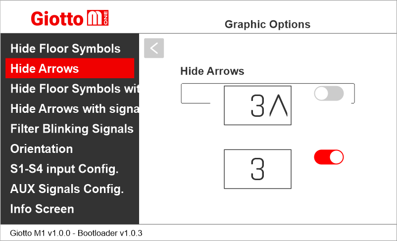
Hide Arrows
Giotto M1 >> Options >> Graphic Options >> Hide Arrows
This option allows to show or hide the arrows on the screen.
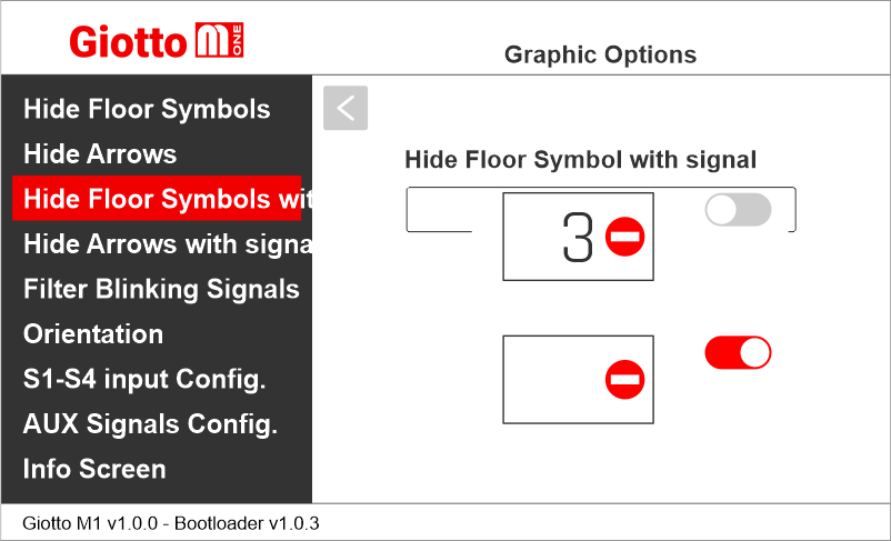
Hide Floor Symbol with signal
Giotto M1 >> Options >> Graphic Options >> Hide Floor Symbol with signal
This option allows to show or hide the floor symbol on the screen when a service message is displayed.
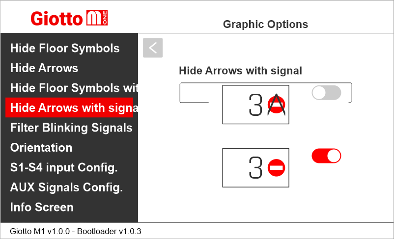
Hide Arrows with signal
Giotto M1 >> Options >> Graphic Options >> Hide Arrows with Signal
This option allows to show or hide the arrow on the screen when a service message is displayed.
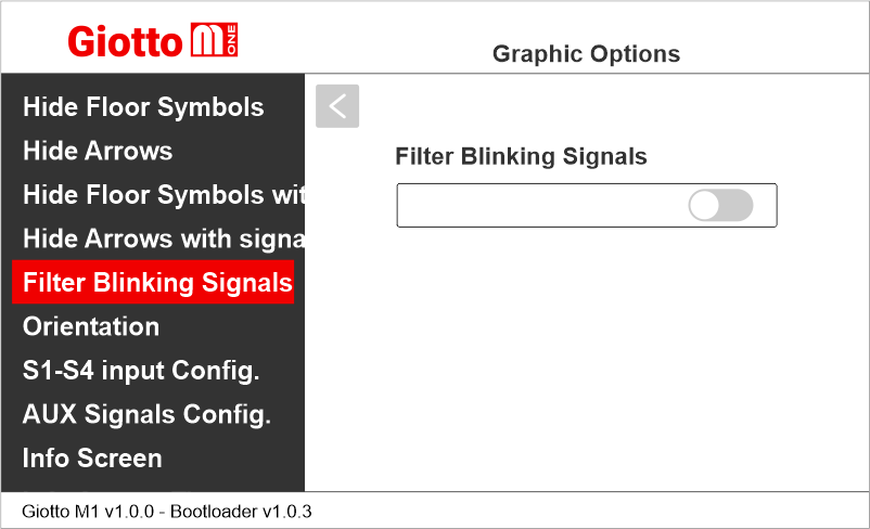
Filter Blinking Signals
Giotto M1 >> Options >> Graphic Options >> Filter Blinking Signals
This option filters blinking signals from controller to avoid unwanted fading effects on TFT screen.
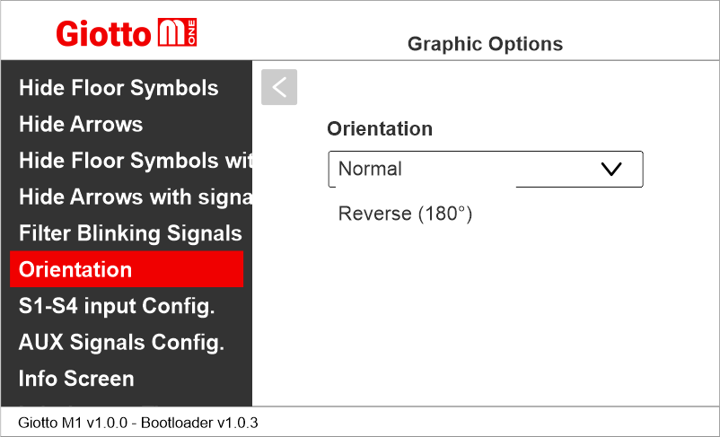
Setting the display orientation
Giotto M1 >> Options >> Graphic Options >> Orientation
This option allows the user to ratote the content of the screen according to the mounting direction of the display.
Setting service message inputs
Giotto M1 >> Options >> Graphic Options >> S1-S4 Inputs Configuration
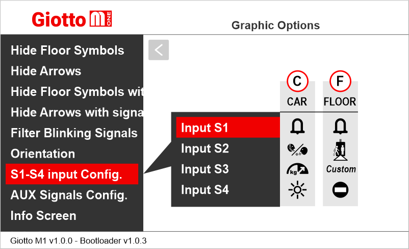
C) Car
F) Floor
See also:
Service Messages wiring
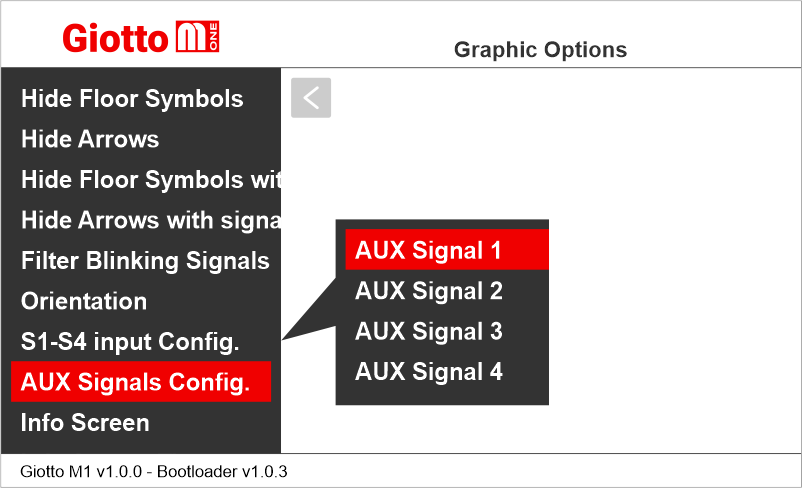
Setting auxiliary signals
Giotto M1 >> Options >> Graphic Options >> AUX Signals Configuration
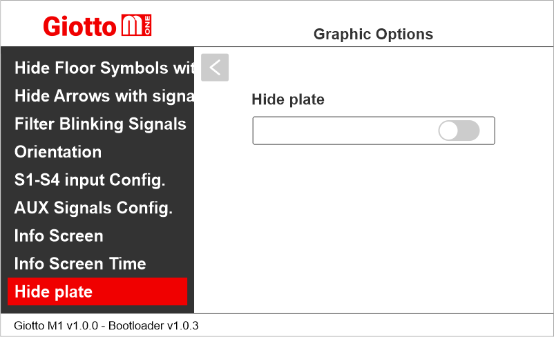
Hide plate
Giotto M1 >> Options >> Graphic Options >> Hide plate
Displaying (or not) the information about the system’s capacity plate data.
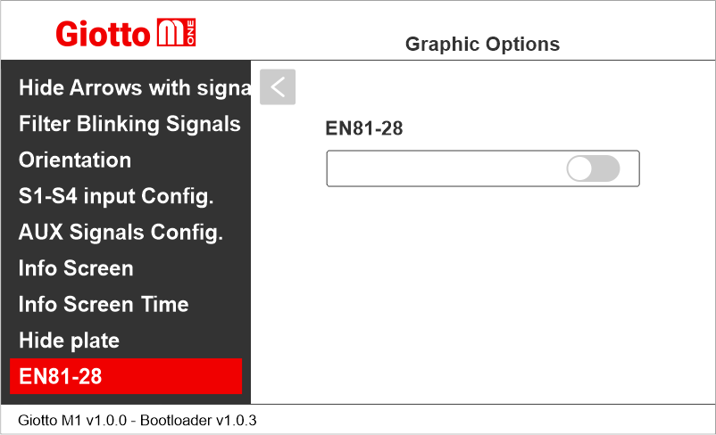
EN81-28
Giotto M1 >> Options >> Graphic Options >> EN81-28
If this setting is enabled, EN81-28 signals (if active) are displayed together. If this setting is disabled, EN81-28 signals are displayed alternately.
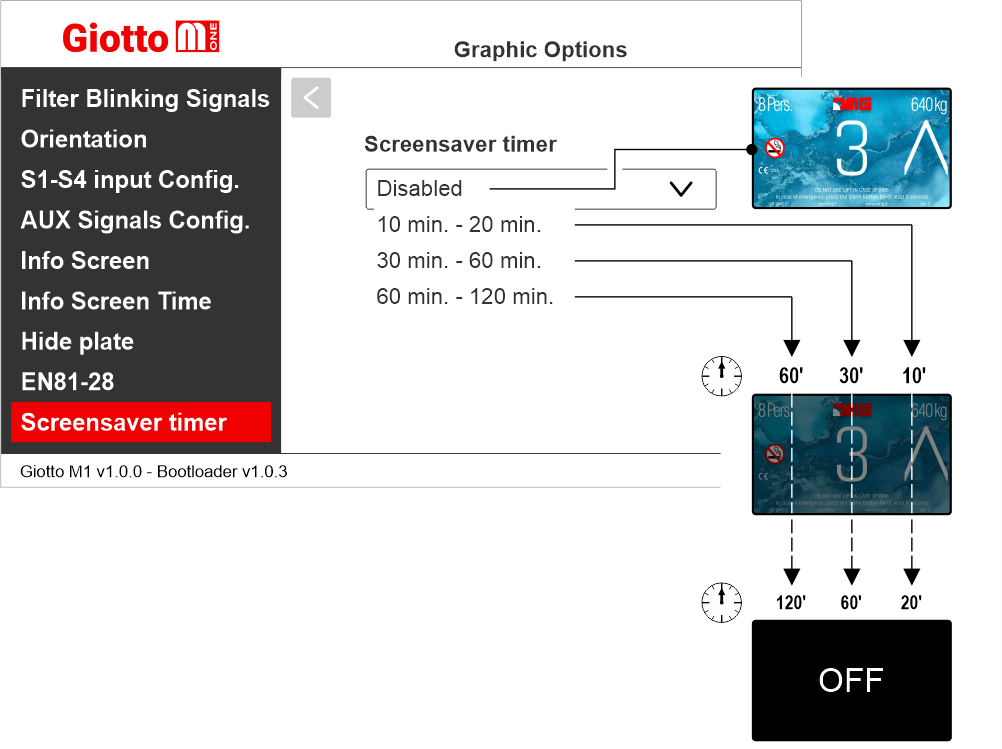
Enabling the energy saving function
Giotto M1 >> Options >> Graphic Options >> Screensaver timer
Enable this option to set the screensaver times.
Giotto M1 >> Options >> Graphic Options >> Hide Floor Symbols
This option allows to show or hide the floor symbol on the screen.
Hide Arrows
Giotto M1 >> Options >> Graphic Options >> Hide Arrows
This option allows to show or hide the arrows on the screen.
Hide Floor Symbol with signal
Giotto M1 >> Options >> Graphic Options >> Hide Floor Symbol with signal
This option allows to show or hide the floor symbol on the screen when a service message is displayed.
Hide Arrows with signal
Giotto M1 >> Options >> Graphic Options >> Hide Arrows with Signal
This option allows to show or hide the arrow on the screen when a service message is displayed.
Filter Blinking Signals
Giotto M1 >> Options >> Graphic Options >> Filter Blinking Signals
This option filters blinking signals from controller to avoid unwanted fading effects on TFT screen.
Setting the display orientation
Giotto M1 >> Options >> Graphic Options >> Orientation
This option allows the user to ratote the content of the screen according to the mounting direction of the display.
Setting service message inputs
Giotto M1 >> Options >> Graphic Options >> S1-S4 Inputs Configuration
C) Car
F) Floor
See also:
Service Messages wiring
Setting auxiliary signals
Giotto M1 >> Options >> Graphic Options >> AUX Signals Configuration
Hide plate
Giotto M1 >> Options >> Graphic Options >> Hide plate
Displaying (or not) the information about the system’s capacity plate data.
EN81-28
Giotto M1 >> Options >> Graphic Options >> EN81-28
If this setting is enabled, EN81-28 signals (if active) are displayed together. If this setting is disabled, EN81-28 signals are displayed alternately.
Enabling the energy saving function
Giotto M1 >> Options >> Graphic Options >> Screensaver timer
Enable this option to set the screensaver times.
Setting the audio options
Giotto M1 >> Audio Options
Adjusting audio level
Giotto M1 >> Audio Options >> _____ Volume
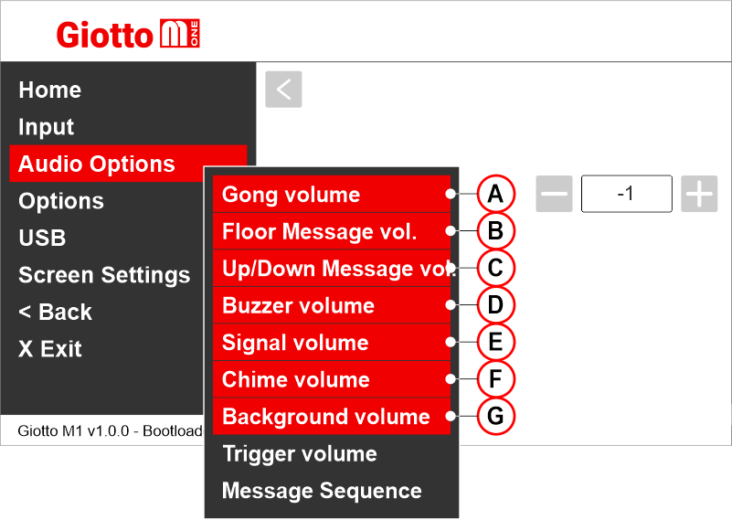
A) Gong volume
B) Messages volume (floor)
C) Direction messages volume
D) Buzzer volume
E) Signals volume
F) Notice of change floor
G) Background volume
Setting the audio messages playback delay
Giotto M1 >> Audio Options >> Trigger Delay
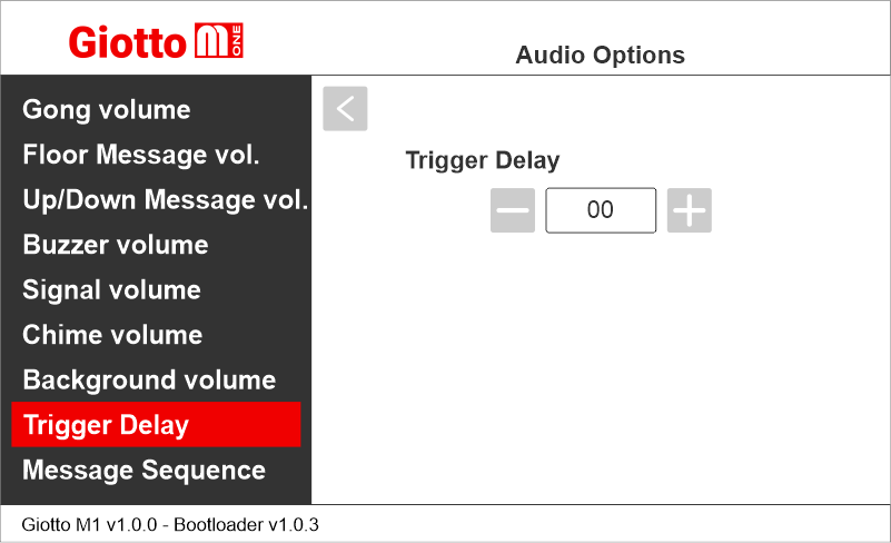
Delay after the trigger activation:
00 = disabled
01 = 100ms
30 = 3000ms (3 seconds)
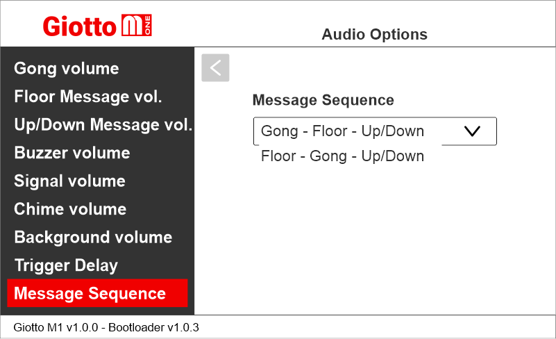
Setting the audio messages playback order
Giotto M1 >> Audio Options >> Message Sequence
Choose the exact sequence of audio messages to be played.
Giotto M1 >> Audio Options >> _____ Volume
A) Gong volume
B) Messages volume (floor)
C) Direction messages volume
D) Buzzer volume
E) Signals volume
F) Notice of change floor
G) Background volume
Setting the audio messages playback delay
Giotto M1 >> Audio Options >> Trigger Delay
Delay after the trigger activation:
00 = disabled
01 = 100ms
30 = 3000ms (3 seconds)
Setting the audio messages playback order
Giotto M1 >> Audio Options >> Message Sequence
Choose the exact sequence of audio messages to be played.
Other settings
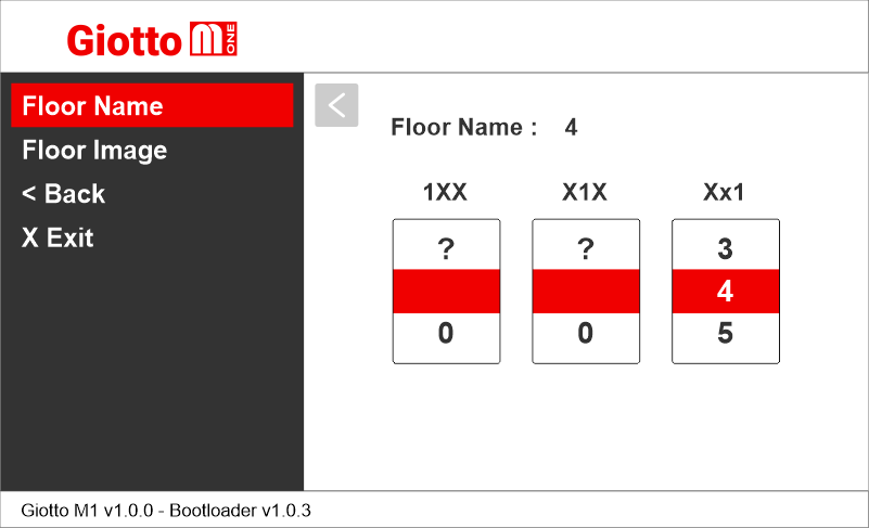
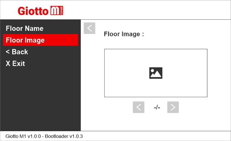
Floor customizations
Press and hold the PRG button for 3 seconds to access the customization menu.
Setting floor numbers and letters
Setting floor image
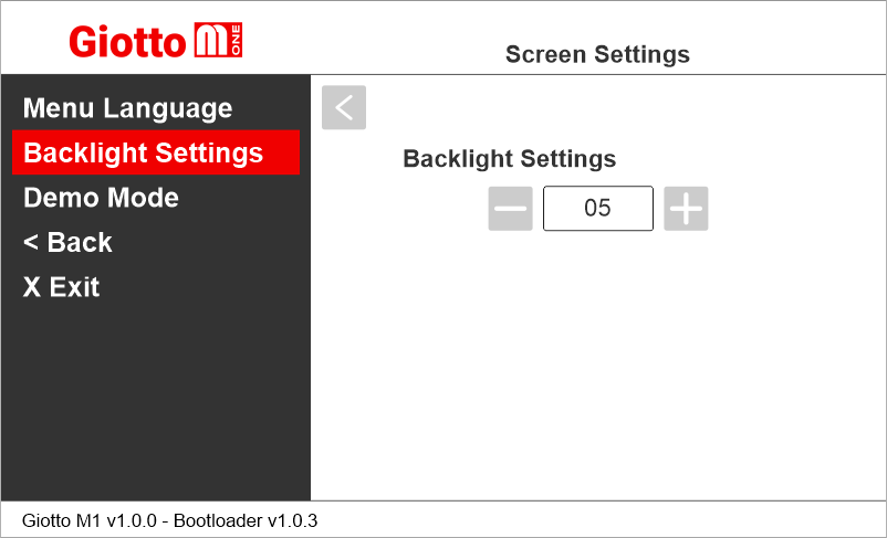
Backlight settings
Giotto M1 >> Screen Settings >> Backlight Settings
The backlight values of the screen will remain fixed and should not be confused with the power saving function..
The backlight values of the screen will remain fixed and should not be confused with the power saving function..
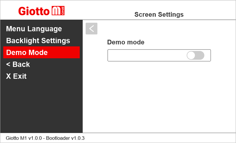
Demo Mode
Giotto M1 >> Screen Settings >> Demo Mode
Reset All Settings
Giotto M1 >> Options >> Reset All Settings
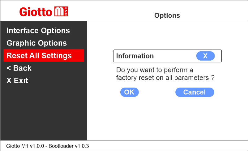
The display original factory settings will be restored and configurations will be deleted.
The display original factory settings will be restored and configurations will be deleted.
Giotto display update
Giotto M1 >> USB
Giotto M1 >> USB >> Import file
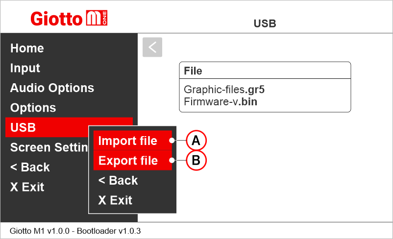
A) It is possible to import both graphic templates (.gr5) and firmware updates (.bin) from a USB stick. Both will be displayed in a context menu. Follow the procedure below.
B) Not available yet.
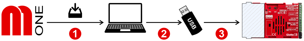
1) Export the chosen configuration (.gr5/.bin) from the MosaicONE cloud software.
2) Copy the file to USB memory (FAT32 formatted / 64GB maximum).
3) Insert the memory directly into the USB port of the Giotto display and use the contextual menu.
A) It is possible to import both graphic templates (.gr5) and firmware updates (.bin) from a USB stick. Both will be displayed in a context menu. Follow the procedure below.
B) Not available yet.
1) Export the chosen configuration (.gr5/.bin) from the MosaicONE cloud software.
2) Copy the file to USB memory (FAT32 formatted / 64GB maximum).
3) Insert the memory directly into the USB port of the Giotto display and use the contextual menu.
Datasheet
| Dimensions | 4,3" | 132 x 80 mm (H20) |
| 4,3" (EN81-71) | 138 x 100 mm (H26) | |
| 5" Back mounted | 125 x 96 mm (H23) | |
| 5" Frontal mounted | ||
| 5,6" | 132 x 129,5 mm | |
| 7" | 177,8 x 144 mm (H20) | |
| 7" (EN81-71) | 198 x 165 mm (H26) | |
| 10,1" | 243 x 169 mm (H35,5) | |
| Screen (Viewable area) | 4,3" | 98,7 x 57,2 mm • 480 x 272 pixel • 65.000 colors |
| 4,3" (EN81-71) | ||
| 5" Back mounted | 111 x 63 mm • 480 x 272 pixel • 65.000 colors | |
| 5" Frontal mounted | ||
| 5,6" | 115,3 x 87,1 mm • 640 x 480 pixel • 65.000 colors | |
| 7" | 157 x 89 mm • 1024 x 600 pixel • 65.000 colors (IPS screen) | |
| 7" (EN81-71) | ||
| 10,1" | 222,7 x 125,3 mm • 1024 x 600 pixel • 65.000 colors (IPS screen) | |
| Power supply (position input) | 12÷24V DC ±10% | |
| Absorption | 4,3" | DISPLAY 12V DC: Max 110mA • 24V DC: Max 70mA PANIC LIGHT 12V DC: Max 110mA • 24V DC: Max 70mA |
| 5" | DISPLAY 12V DC: Max 270mA • 24V DC: Max 150mA PANIC LIGHT 12V DC: Max 242mA • 24V DC: Max 125mA |
|
| 5,6" | DISPLAY 12V DC: Max 270mA • 24V DC: Max 150mA PANIC LIGHT 12V DC: Max 242mA • 24V DC: Max 125mA |
|
| 7" | DISPLAY 12V DC: Max 230mA • 24V DC: Max 134mA PANIC LIGHT 12V DC: Max 210mA • 24V DC: Max 110mA |
|
| 10,1" | DISPLAY 12V DC: Max 220mA • 24V DC: Max 120mA PANIC LIGHT 12V DC: Max 220mA • 24V DC: Max 120mA |
|
| Indicators inputs | S1 / S2 / S3: 12÷24V DC ±10% (opto-isolated) Impedance = 3Kohm |
|
| IP protection | 4,3"/5,6"/7"/10,1" | IP44 |
| Operating temperature | 4,3" | -10°C ÷ +50°C |
| 5" | ||
| 5,6" | ||
| 7" | ||
| 10,1" | ||
Software

MosaicONE Guide
Troubleshooting
| Fault description | Giotto 4,3" / 5" | Giotto 5,6" / 7" / 10,1" | |
|---|---|---|---|
| Installation errors | The display does not light up | Check for the presence of 12/24VdC voltage. | |
| Make sure that the type of voltage complies with that required (direct voltage, not alternating, not rectified). | |||
| Check the correct polarity on the power terminals. | |||
| Even if the display seems off, check that the red FAIL led on the back is not on, if it is, in this case the problem would be of a different nature. Please contact DMG. | |||
| Check that the characteristics of the system can meet the consumption requirements in terms of current of the devices, as recommended and for correct operation, it may be necessary to use additional power supplies (available from DMG). | |||
| Display Flashes or restarts continuously | Make sure that the type and voltage value comply with those required, if the problem persists it can be attributed to a HW defect. | ||
| Steady red LED | Device in FAIL. Indicates a Serious system ERROR, inherent in a hardware defect or other unresolvable defect. Please contact DMG. | ||
| Flashing red LED | Device in FAIL. Indicates a generic system ERROR, in this case there may have been a problem relating to the graphic or fw programming of the device, an update via USB may be sufficient. Ex: the display shows "NO GRAPHIC FOUND" associated with the flashing red LED (see error messages). | ||
| The display does not show numbers and/or arrows | Make sure that the type and voltage value comply with those required for the inputs, make sure you have correctly set the type of common. | ||
| Error messages | Firmware file not found | No firmware (.bin) found on inserted stick. The problem may appear when the graphics (.CFC) have been updated by inserting the USB stick with the display off and then turning it on. The correct procedure for loading .CFC files is to insert the key with the display on. | |
| Graphic file not found | No graphic file (.cfc) found on the inserted stick. Check the name of the file, the formatting parameters of the flash drive and, if necessary, carry out a non-fast format of the flash drive from Windows. Flash drives of 32GB and up will probably not work because it is not possible to format them in a format readable by the display. | ||
| Waiting USB for firmware | The display is waiting for a firmware (.bin) to be loaded via USB stick. | ||
| Waiting USB for graphic configuration | The display is waiting for a graphical configuration file (.cfc) to be loaded via USB stick. | ||
| Wrong RES | This message appears when the resolution of the configuration is not the same as the mounted TFT panel. Load the suitable configuration. | ||
| Disk error: check that USB key is formatted in FAT32 or File read error - please format in FAT32 | The device does not accept pen drives that are not formatted in FAT32. Format the pen drive in FAT32 and repeat the operation |
||
| Error Load Container Waiting USB | These error messages are due to the KNOWN problem of the RAM defect. This defect has now been resolved on the new versions, however, it could recur on devices already installed on which a firmware upgrade is made from a 1.XX version to a 2.XX one. The display firmware needs to be updated. |
||
| INTERFACE_RUN Error | |||
| Assert image.c line xxx | |||
| Wrong recognition Coding interface | For displays that use coding interfaces (slots), the data of the inserted interface is shown on the screen at startup. If an inconsistency occurs, the defect is to be attributed to the HW. | ||
| The display turns on but does not start up or freezes during start up | If the loading bar freezes, it could be a graphics file problem. Regenerate the file (.cfc) and repeat the loading procedure. | ||
| The display shows the indication "E" followed by a number X | In this case, it is a generic error indication due to an incorrect setting of the display. Please contact DMG | ||
| Display defects | The display shows vertical lines | If the lines are fixed and black, please contact DMG. | |
| The display shows horizontal lines | |||
| The display is white | Please contact DMG. | ||
| The display has inverted colors or with a "negative" effect | Please contact DMG. | ||
Download
| Reference | Version | Link |
|---|---|---|
| V4 version | V4 | Download PDF (English) |
| MosaicONE version | 1.0 | Download PDF (English) |