(v 1.0)
Safety and usage cautions
Before installing our products, we recommend you to consult the section about safety and usage cautions at the link below

Disposal and Recycling Information

The crossed-out wheeled bin symbol shown on the product, battery, documentation or packaging indicates that batteries and electronic products must be disposed of separately at the end of their service life and must not be disposed of with normal household waste. It is the user’s responsibility to dispose of the equipment by delivering it to a designated collection point or service for the separate recycling of electrical and electronic equipment (RAEE) and batteries, in accordance with local regulations.
Proper collection and recycling help ensure that electrical and electronic equipment (AEE) is recycled in a manner that conserves valuable materials and protects the environment and human health from potential negative effects resulting from improper use, accidental breakage, damage and/or incorrect end-of-life treatment. For further information on where and how to dispose of RAEE, please contact your local authorities, your retailer, or your local waste disposal service, or visit the relevant website.
Reduction of Restricted Substances
This device and any associated electrical accessories comply with applicable local regulations on the restriction of certain substances in electrical and electronic equipment, including the EU REACH and RoHS Directives, as well as those relating to batteries (when included).
Introduction
PROPHESIX is DMG’s monitoring device designed for the remote supervision of any elevator, fully independent of the controller.
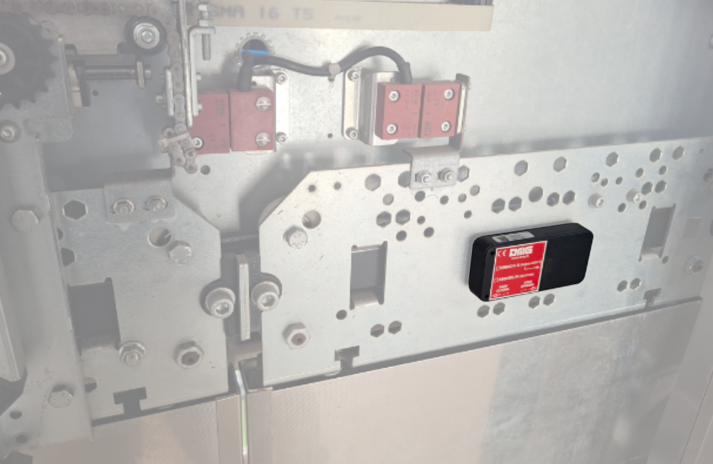
Installed on the top of car, PROPHESIX features sensors for detecting car movement and position, along with configurable inputs and outputs enabling precise system control.
System components
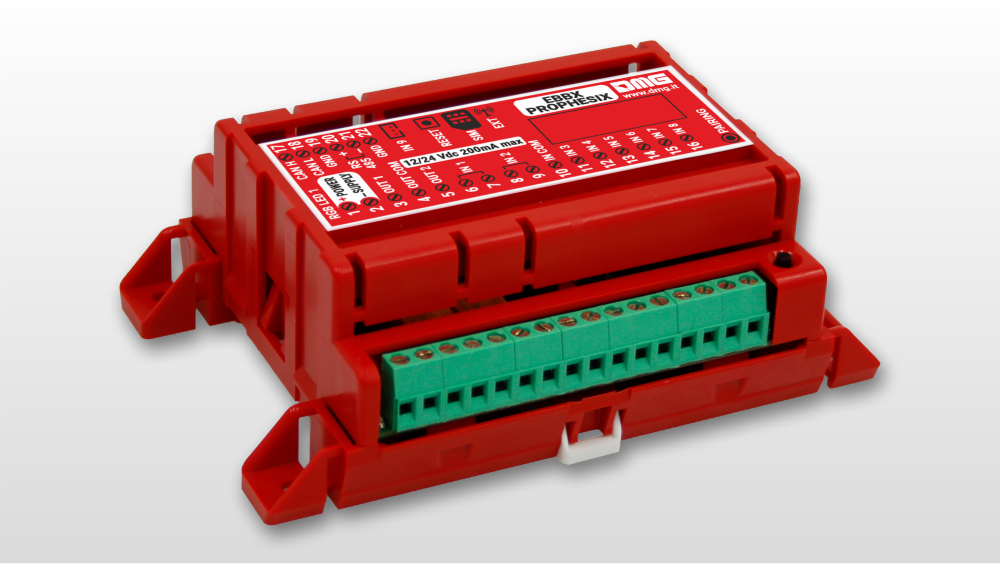
Electronic control unit
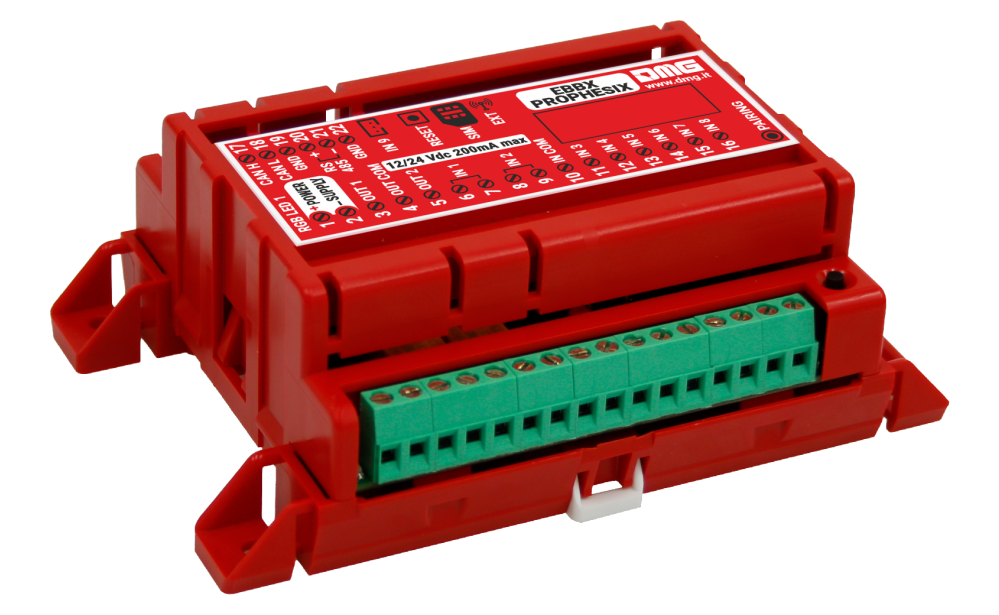
It is an advanced device installed on the top of elevator car, designed to continuously monitor elevator movements and position through integrated sensing technology.
The device provides two outputs for simulating car calls to the top and bottom floors or other remote commands, along with 8 inputs for optional sensors, enabling detailed and reliable monitoring of the elevator status (floor detection, door operation, out-of-service, maintenance, etc.).
Integrated 4G connectivity ensures real-time communication with a remote server, while WiFi and BLE interfaces allow connection to external sensors and to an optional external modem, ensuring service continuity even in environments with limited signal coverage inside the elevator shaft.
The device can be easily configured via smartphone and cloud platform, offering maximum flexibility and ease of installation.
Supplied with an included 1 GB data SIM, it guarantees connectivity for up to 5 years, reducing operating costs and maintenance requirements.
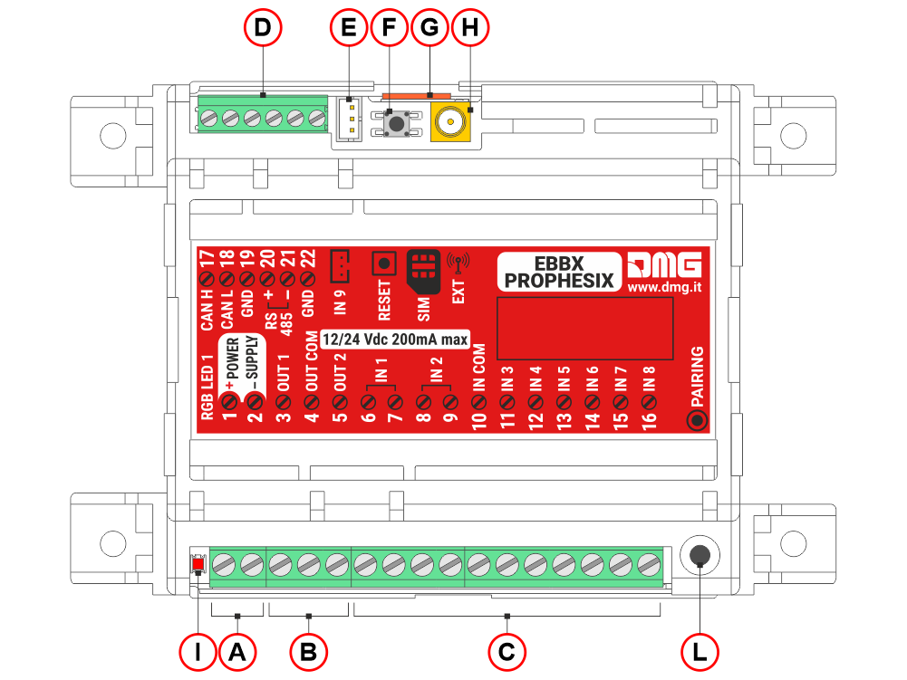
A) Power supply input (12/24Vdc 200mA max)
B) Two outputs for simulating car calls to the top and bottom floors or other remote commands
C) 8 opto-isolated, configurable inputs for optional sensors, enabling more accurate monitoring of the lift status (floor detection, door operation, out-of-service, maintenance, etc.).
D) Function not yet available; reserved for future development.
E) Light sensor
F) Reset SW button
G) micro-SIM card for 4G connection
H) input for 4G mobile antenna
I) Diagnostic LED
L) Pairing button
Door sensor
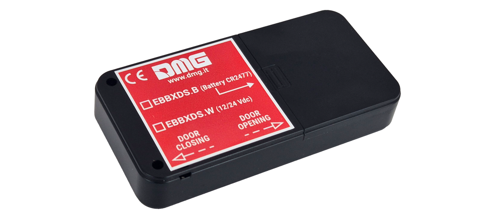
Optional device installed on the car doors for monitoring door movement.
The device is equipped with an internal battery and BTLE connectivity for wireless communication with the control unit.
Note: Instead of using the door sensor, the door operation can be monitored through the door open and door close limit switches by wiring them to the Prophesix inputs.
FUSION app / dashboard
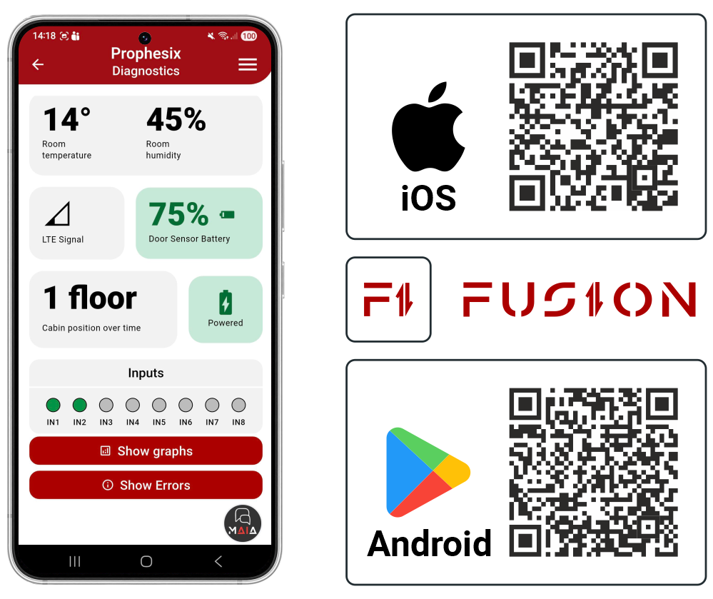
The DMG FUSION cloud platform collects and processes data transmitted by the Prophesix device.
Through FUSION, it is possible to:
• Configure the Prophesix system.
• Remotely monitor the elevator system status.
• Analyze data and statistics related to elevator usage and operating conditions over time.
The main available information includes:
• Elevator status logging (e.g. Normal operation, Inspection mode, Out of service)
• Car and door movement logging (up/down trips, operating time, distance traveled)
• Anomaly logging (e.g. interrupted travel, sudden accelerations/decelerations, door malfunctions)
• Scheduling of test calls to verify the actual operating condition of the elevator
Device pairing with the FUSION cloud platform
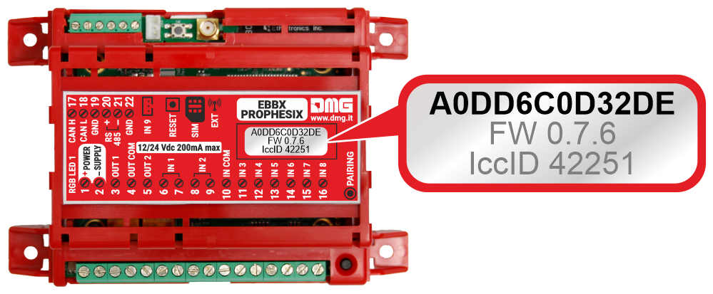
For system operation, the Prophesix device must be associated with the relevant FUSION account.
The device is identified by its unique MAC address, shown on the label on the device, as shown in the image.
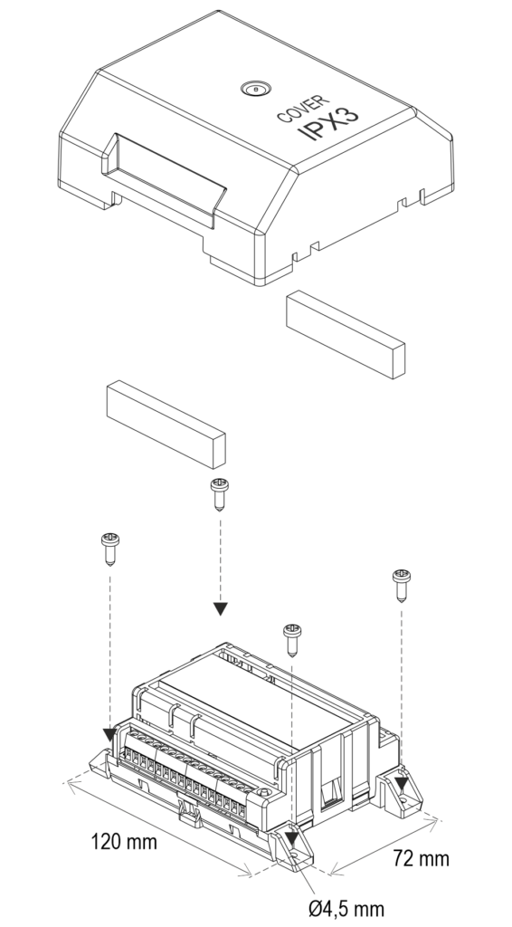
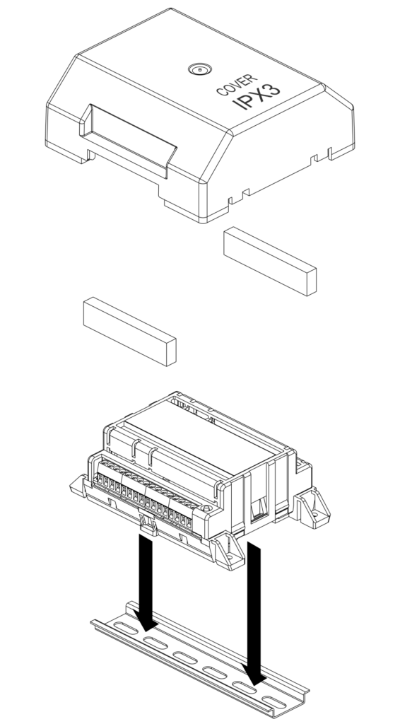
Mounting
Electronic control unit
Fixing with screws
DIN rail fixing
Door sensor
The door sensor must be installed on the car doors, secured with double-sided tape (supplied with the device), and positioned as shown in the image.
Installation
First power-on
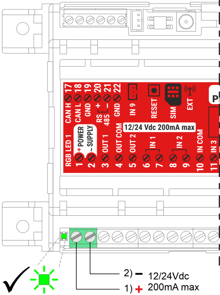
Power on the device and wait until the status LED turns green.
Prophesix then starts transmitting car movement data and environmental parameters to the FUSION cloud platform.
Note:
Prophesix includes an internal energy reserve that keeps the device operational for approximately 5 minutes in the event of a power loss. Full backup capacity is reached about 2 hours after power-up.
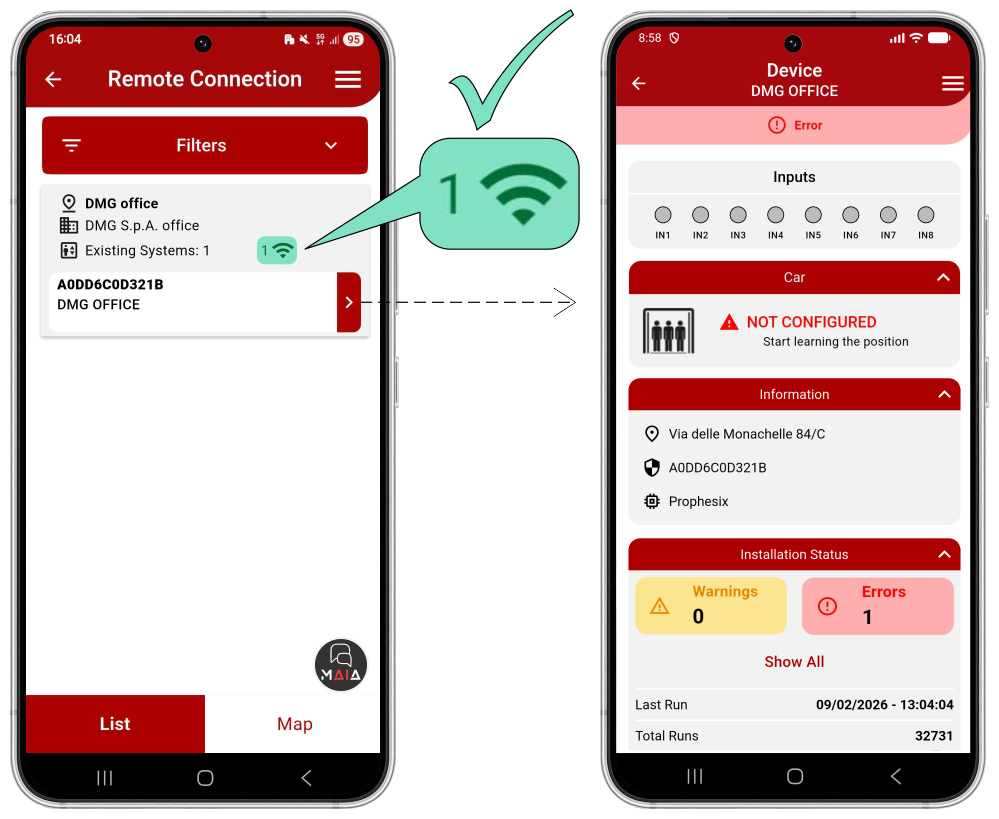
- Open the FUSION app and select PROPHESIX.
- Log in via REMOTE connection.
- Check that the device appears in your device list and that it is connected (green icon).
- Select the device to be managed from the drop-down menu on the right.
The main informations about the elevator status are displayed on the main page of the FUSION app.
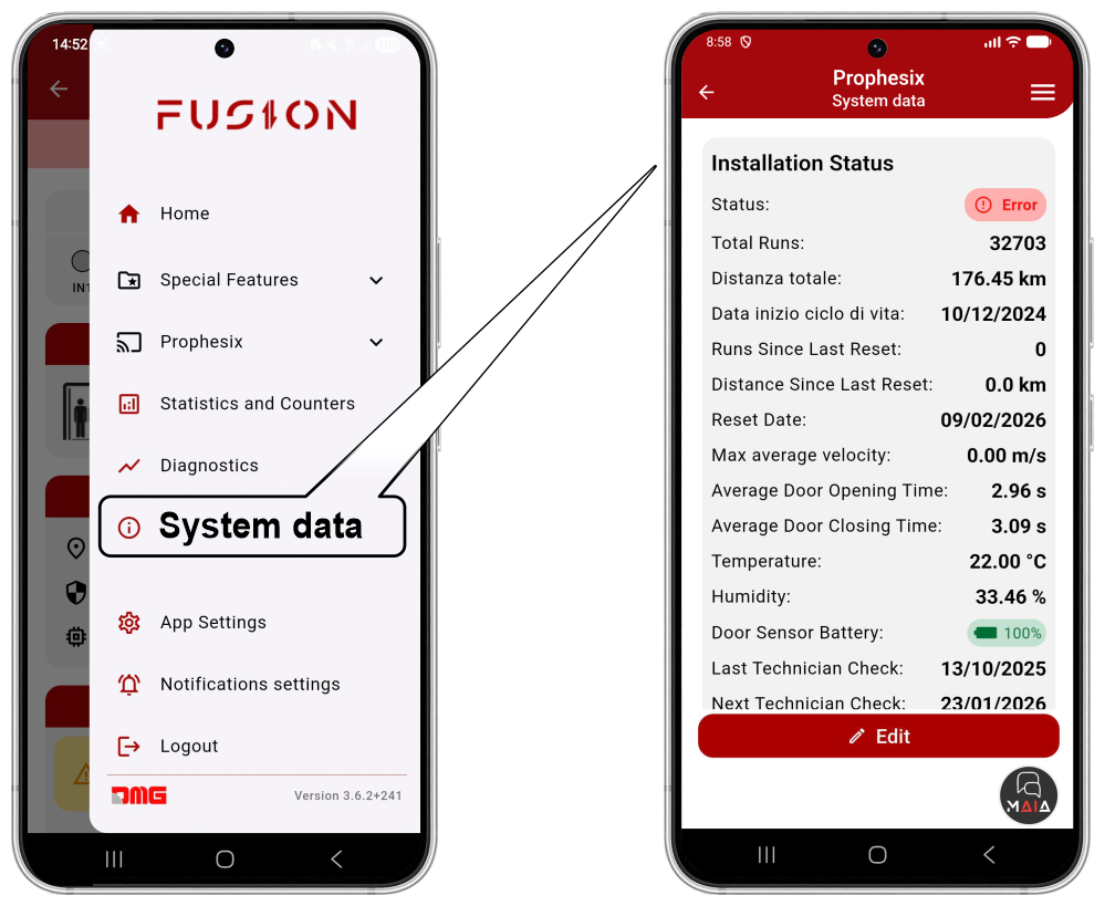
The System Data menu allows the user to enter and modify the main system parameters of the installation where the Prophesix device is installed.
Door sensor pairing (optional)
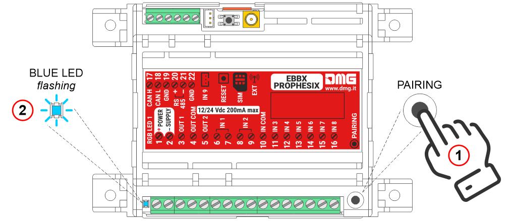
Press the pairing button on the control unit and wait for the blue LED to start flashing.
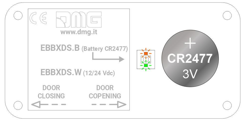
Remove the cover and install the supplied battery; the LEDs will flash alternately for a few seconds.
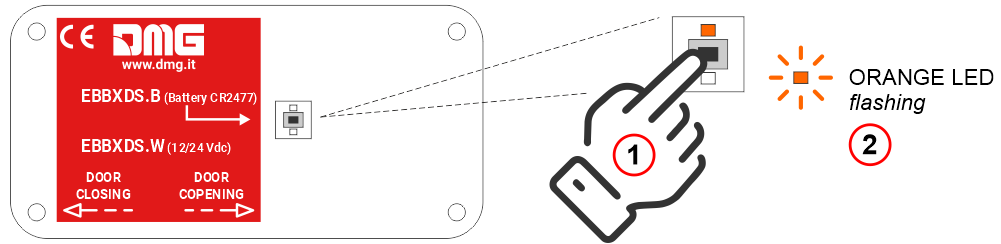
Press the pairing button on the door sensor, using a screwdriver, and wait for the orange LED to start flashing.
Door sensors configuration
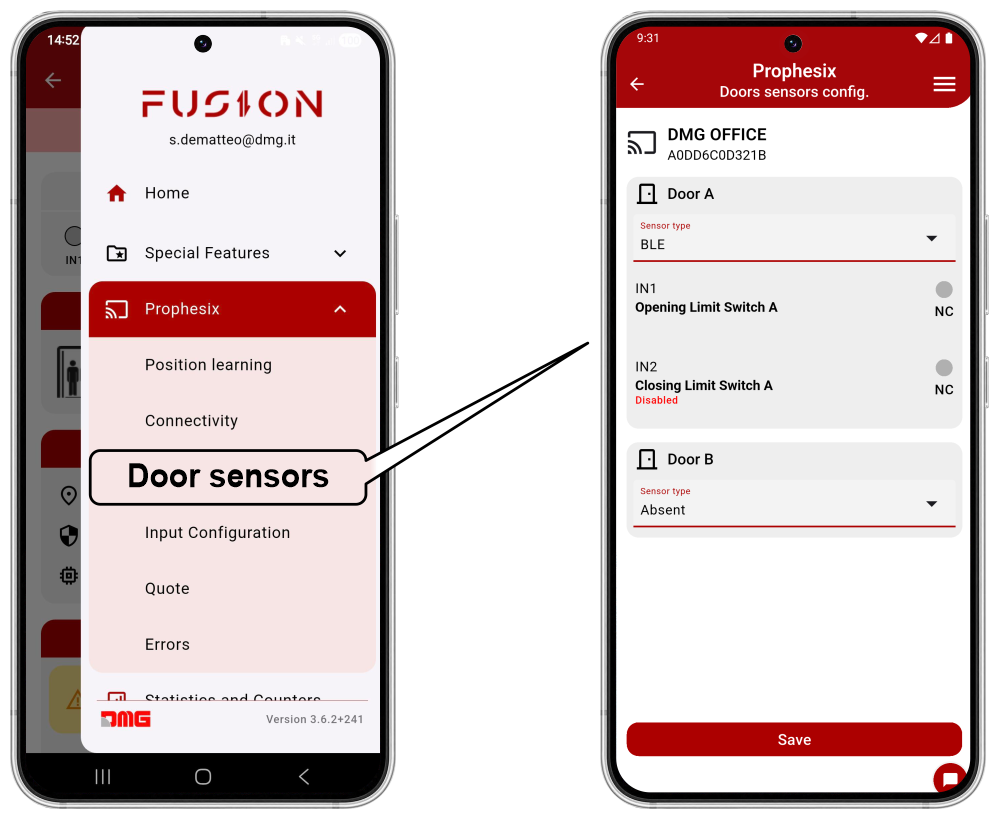
From this menu, you can select the door monitoring method:
- Door Sensor (BLE)
- Limit Switch
Cabin position learning procedure
To put the system into operation, follow the guided procedure in the app, which learns the floor heights (inter-floor distances) by performing a series of cabin calls.
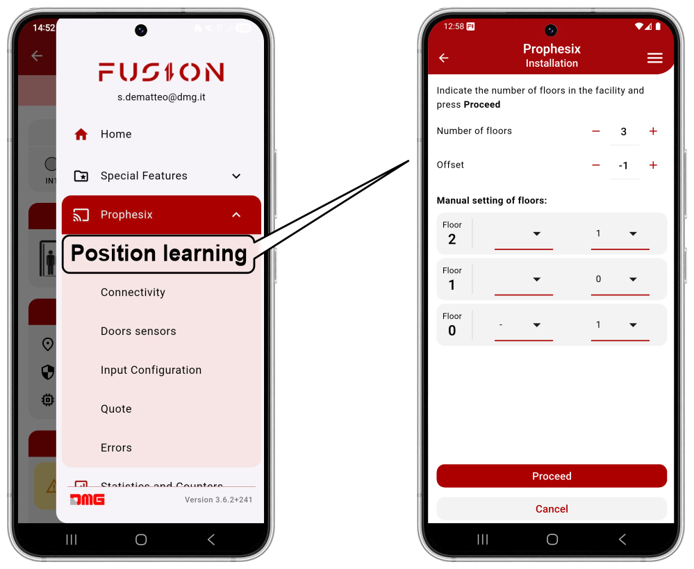
From the FUSION app:
- Select the Prophesix device;
- Open the top-right menu and select “Prophesix”, then “Position learning”;
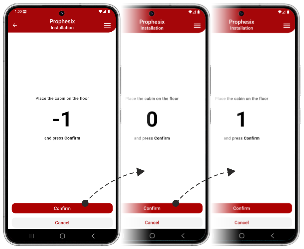
- Move the cabin to the lowest floor.
- Call all floors from bottom to top.
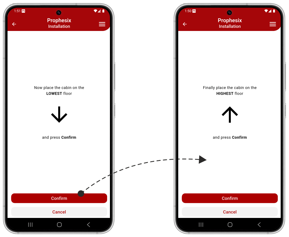
- Perform a full run from the highest floor to the lowest floor.
- Perform a full run from the lowest floor to the highest floor.
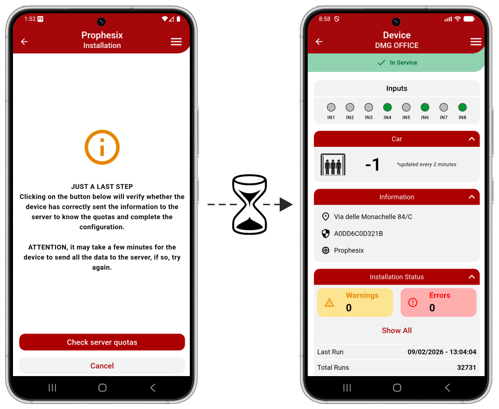
At the end of the procedure, without moving the elevator, wait for the data to be transferred from the Prophesix device to the Fusion cloud, which will take approximately 2 minutes.
If the procedure is not successful, it must be repeated.
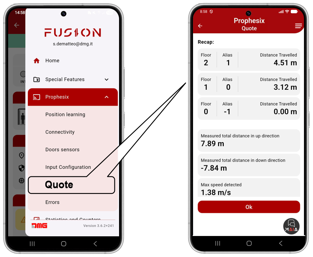
The acquired data may be verified in the “Prophesix-Quote” menu.
Inputs & Outputs configuration
Digital inputs
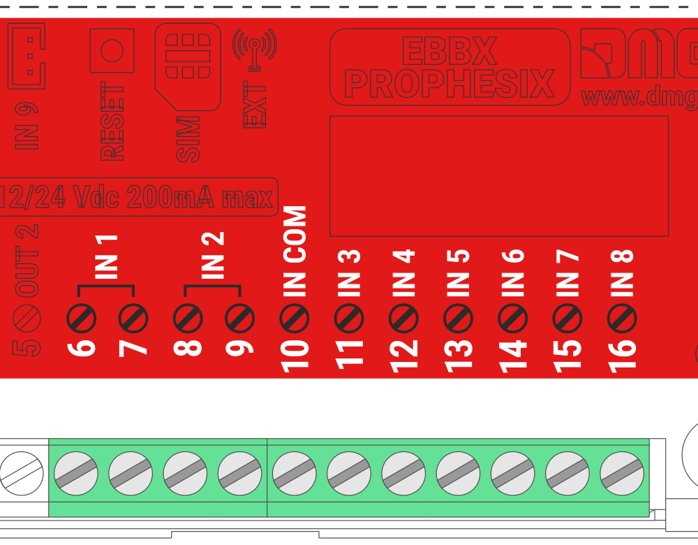
Prophesix features 8 configurable digital inputs that can be assigned to sensors, signals, or other devices.
All inputs are opto-isolated and non-polarized
- Activation Voltage: 12/24 Vdc
- Maximum input current: 5 mA @ 24 V).
- Inputs IN1 and IN2 are electrically independent from the other inputs.
- Inputs IN3 to IN8 share the common terminal “IN COM”.
| Input | Description |
|---|---|
| IN1 | Door A open limit switch |
| IN2 | Door A close limit switch |
| IN3 | Out of service |
| IN4 | Maintenance mode |
| IN5 | Car at floor |
| IN6 | Overload |
| IN7 | Alarm |
| IN8 | Alarm battery low |
The default configuration sets all inputs as inactive, with assignments as indicated in the table.
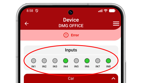
The activation status of the inputs is displayed in the FUSION app
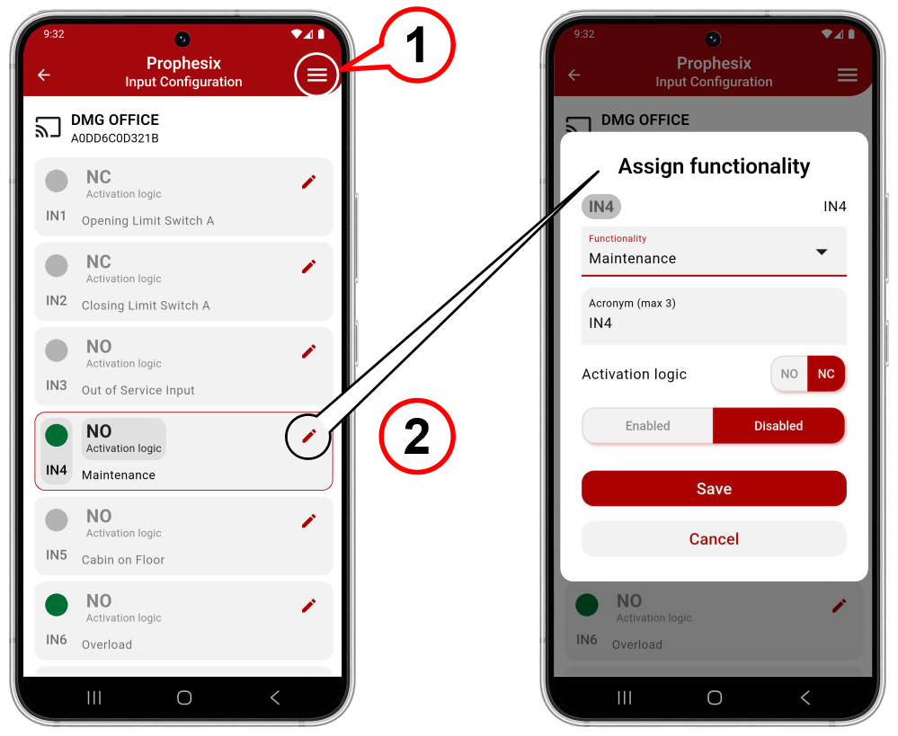
To modify the configuration of individual inputs:
1) Access the top-right menu.
Menu > Prophesix > Input configuration
2) Enter the single input edit mode.
Digital outputs
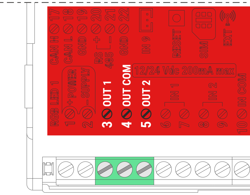
Prophesix features 2 configurable digital outputs that can be assigned to special functions.
Each of the outputs OUT1 and OUT2 can be assigned to one SPECIAL FUNCTION only.
- Two relay outputs with volt-free contacts (max. 24 V, 1 A)
- OUT1 and OUT2 share the common terminal “OUT COM”
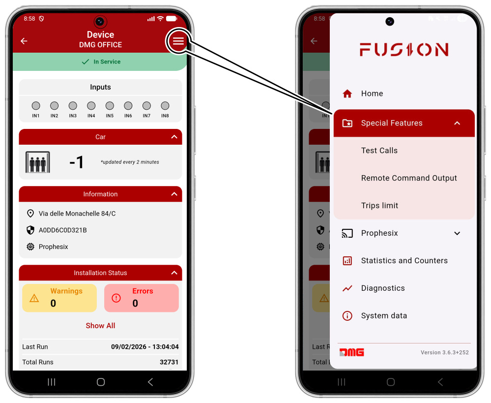
To modify the configuration of individual outputs, access the top-right menu
Menu > Special Features
Here you can select and configure the special functions to be assigned to outputs OUT1 and OUT2.
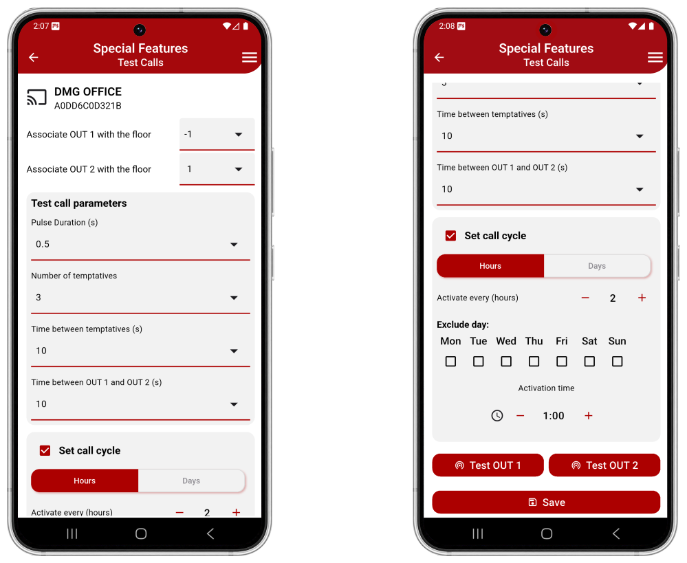
Test Calls
This function allows test calls to be performed in order to remotely verify the correct operation of the lift.
The remote command can be activated either automatically (scheduled) or manually.
To perform test calls, the outputs must be wired in parallel with the car call pushbuttons, typically those of the terminal floors, and the relevant parameters must be configured via the FUSION APP.
- Press the OUT1 and OUT2 buttons to perform a manual call.
- The successful registration of the call can be verified by connecting the pushbutton indicator lights to the Prophesix inputs.
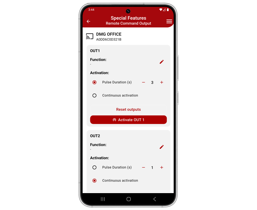
Remote Command Output
This function allows remote activation of outputs OUT1 and OUT2.
Activation can be set as pulse mode (with programmable duration) or continuous mode.
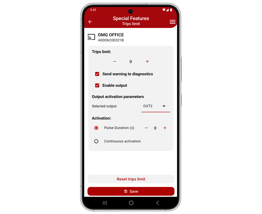
Trips limit
This function allows setting a preset number of lift trips and, when the preset value is reached, sending a notification to the user and/or activating a Prophesix output.
Connectivity
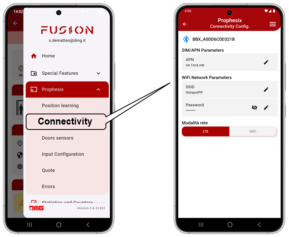
From this menu, you can configure the type of network connection, selecting between 4G LTE (default) and Wi-Fi.
To modify this setting, you must be connected to the device via Bluetooth®.
- By accessing via local connection, the system scans for Prophesix devices within Bluetooth® range.
- By accessing via remote connection, you directly access the registered device.
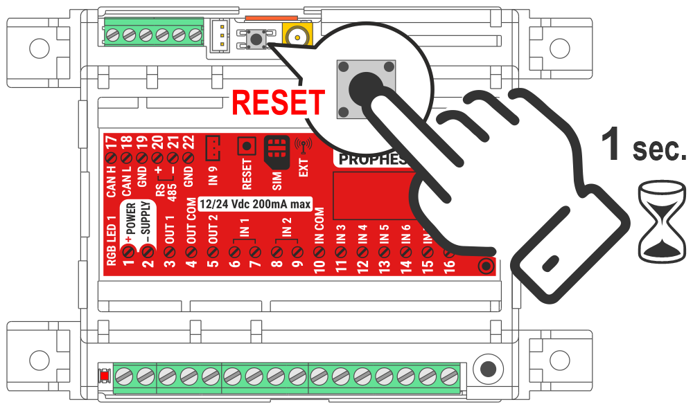
To apply the modified parameters, restart the Prophesix device by pressing the RESET pushbutton for 1 second.
Diagnostics
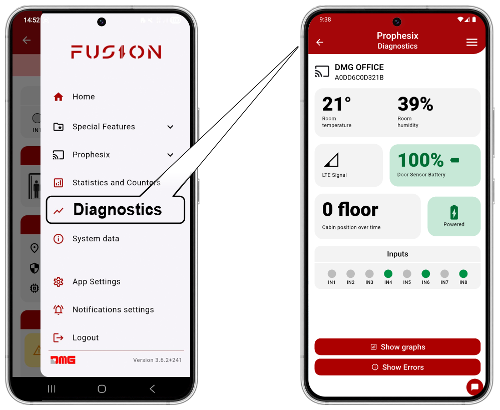
From this menu, you can view the diagnostic data of the Prophesix device.
The data are displayed in real time; by selecting “Show graphs,” you can view their trend over time.
The available data are as follows:
- Temperature and humidity
- LTE signal
- Power status
- Door sensor battery status
- Errors and Warnings
Statistics and Counters
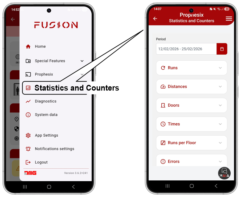
From this menu, you can view statistical data related to system operation both as counters (numeric format) and as statistics (graphical format).
Data can be displayed either as total values or for the selected period.
The available data are as follows:
- Elevator runs
- Distance traveled
- Door Opening/Closing cycles
- Upward/Downward run times
- Elevator runs per floor
- Errors and Warnings
- System Availability
- Acceleration trend
- Speed trend
- Temperature and humidity
- Run/Standby time
Troubleshooting
Prophesix is designed to detect and store a range of errors and warnings, accessible via the FUSION app under the menu:
Menu > Prophesix > Errors
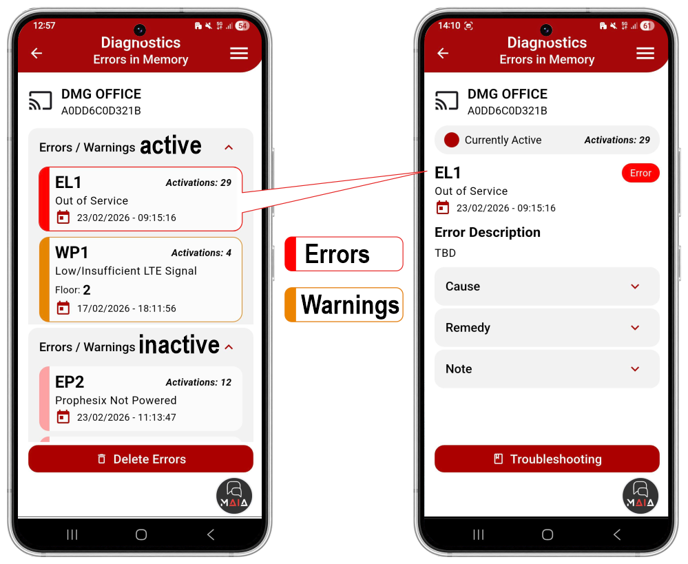
Errors are displayed as either active and/or inactive.
Events are further classified as:
- E) Errors – displayed in red
- W) Warnings – displayed in yellow
Each event is also identified by a letter indicating its type:
- P) Prophesix device errors
- L) Lift errors
- S) Door sensor errors
| Code | Description | Cause | Remedy |
|---|---|---|---|
| EP1 | Prophesix Offline | 4G LTE signal is too weak or absent. | If the issue is frequent or persistent, connect the device to a Wi-Fi network. |
| EP2 | Prophesix Not Powered | Device power is absent. (In the event of a power loss, the device will continue to operate for 5 minutes.) | Check and restore device power. |
| EP3 | Door Sensor Not Paired | The door sensor is configured, but Prophesix does not receive data from the door sensor. | • Check that the door sensor is correctly installed. • Check the door sensor battery status. • Verify that the RGB LED turns light blue following a door movement. |
| EP4 | Cabin Position Loss | A cabin position calculation error has been detected and corrected. | Check whether the 4G LTE signal is sufficient. |
| EP9 | Temperature Threshold Error | The temperature in the shaft measured by the device is outside the high and low thresholds set in the notification settings. | Ensure that the measured temperature is not critical for normal elevator operation. |
| EP10 | Humidity Threshold Error | The humidity in the shaft measured by the device is outside the set threshold. | Ensure that the measured humidity is not critical for normal elevator operation. |
| EP11 | Accelerometer Error | An inconsistency has been detected between the data read from the device’s internal accelerometer and the data read from the barometric sensor. | Occasional errors may occur in the event of sudden atmospheric pressure changes. If the error persists, replace the device. |
| EP12 | Altimeter Error | An inconsistency has been detected between the data read from the device’s internal barometric sensor and the data read from the accelerometer. | Occasional errors may occur in the event of sudden atmospheric pressure changes. If the error persists, replace the device. |
| WP1 | Low or Insufficient LTE Signal | The 4G LTE signal is below the configured minimum value. The 4G signal is low in the area where the device is installed or in the elevator shaft. | If the issue persists, set up a Wi-Fi connection to ensure optimal device operation. |
| WP2 | Future Use | ||
| WP3 | Future Use |
Lift errors and warnings
| Code | Description | Cause | Remedy |
|---|---|---|---|
| EL1 | Elevator Out of Service | The OUT OF SERVICE input has been active for longer than the configured time in the notification settings. | Check the conditions that have caused the elevator to go out of service. |
| EL2 | Permanent Cabin Overload | The OVERLOAD input has been active for longer than the configured value. | • Check that there is no excessive load in the cabin. • Verify the correct operation of the load weighing device or any installation issues. |
| EL3 | Permanent Photocell | The PHOTOCELL input has been active for longer than the configured value | • Check that there are no obstacles in front of the door. • Verify the correct operation of the photocell and/or the moving door edge, or any other installation issues. |
| EL4 | System Power Loss | The MAINS POWER input has been active for longer than the configured value. Information comes from the control logic power supply in the machine room panel, or from the phase-monitoring relay in the panel, and/or equivalent devices. | Check for any power supply issues in the system. |
| EL5 | Cabin Light Power Loss | The CABIN LIGHT POWER input has been active for longer than the configured value. Information comes from a relay connected to the cabin light power line (230 VAC), or directly from the 12/24 V power supply of the cabin light, or from a cabin light sensor. | Check for any power supply issues with the cabin light. |
| EL6 | Permanent Occupied | The OCCUPIED input has been active for longer than the configured value. | Check the conditions that cause the system to be in an occupied state (e.g., manual landing door left open). |
| EL7 | Alarm Battery Low | The ALARM BATTERY LOW input has been active for longer than the configured value. Information comes from a relay monitoring the alarm battery status, from the telephone dialer, and/or from equivalent devices. | Check the alarm battery status and replace it if necessary. |
| EL8 | Fire Sensor | The FIRE SENSOR input has been active for longer than the configured value. Information comes from a fire sensor and/or equivalent devices. | Check the status of the fire sensor. |
| EL9 | Pit Water | The PIT WATER SENSOR input has been active for longer than the configured value. Information comes from a pit water sensor and/or equivalent devices. | Check the status of the pit water sensor. |
| EL10 | Door A Not Opened | The opening of DOOR A was not detected at the end of the travel. | Check the correct operation of DOOR A. |
| EL11 | Door A Not Closed | The closing of DOOR A was not detected at the end of the travel. | Check the correct operation of DOOR A. |
| EL12 | Door B Not Opened | The opening of DOOR B was not detected at the end of the travel. | Check the correct operation of DOOR B. |
| EL13 | Door B Not Closed | The closing of DOOR B was not detected at the end of the travel. | Check the correct operation of DOOR B. |
| WL1 | Inspection | The INSPECTION input is active. Signal comes from the machine room panel or from the inspection control panel. | |
| WL2 | Stop Outside Door Zone | The elevator has stopped outside the DOOR ZONE. Signal comes from the machine room panel or from an optical, magnetic, or mechanical sensor installed on the cabin. | Check the stopping accuracy at the floor. |
| WL3 | Overload | The OVERLOAD input is active. Signal comes from the machine room panel or from the cabin load monitoring device. | Check the causes that trigger the cabin overload detection. |
| WL4 | Delay Since Last Trip | No trips have been detected for a period longer than the configured time, on the configured days and time slots. | Check that the system is operating correctly (e.g., perform a test call and verify that the trip is executed). |
| WL5 | No Response to Test Cal | No trips were detected following a scheduled test call (SPECIAL FUNCTIONS / TEST CALLS). | Check that the system is operating correctly (e.g., perform a test call and verify that the trip is executed). |
| WL6 | 1st Warning – Trip Limit Reached | The configured number of trips (SPECIAL FUNCTIONS / TRIP NUMBER LIMIT) is nearly reached. | |
| WL7 | 2nd Warning – Trip Limit Reached | The configured number of trips (SPECIAL FUNCTIONS / TRIP NUMBER LIMIT) has been reached. | |
| WL8 | Upward Trip Time Too Long | The duration of the complete upward trip is too long compared to the learning trip. | Check that the elevator is operating correctly. Ambient temperature may affect the trip time (e.g., very cold oil in a hydraulic system). Cabin load may also affect the trip time. |
| WL9 | Downward Trip Time Too Long | The duration of the complete downward trip is too long compared to the learning trip. | Check that the elevator is operating correctly. Ambient temperature may affect the trip time (e.g., very cold oil in a hydraulic system). Cabin load may also affect the trip time. |
| WL10 | Sudden Trip Interruption | A sudden interruption of the elevator’s movement has been detected. | Check for possible causes of the unexpected stop (e.g., false contacts in the door circuits). |
| WL11 | Maximum Speed Anomaly Compared to Learning Trip | A speed value of the elevator has been detected that differs from the value recorded during the learning trip. | Check that the elevator is operating correctly. Ambient temperature may affect the system’s maximum speed (e.g., very cold oil in a hydraulic system). Cabin load may also affect the maximum speed. |
| WL12 | Deceleration Anomaly Compared to Learning Trip | A deceleration value at elevator stop has been detected that differs from the value recorded during the learning trip. | Check that the elevator is operating correctly. |
| WL13 | Door A Middle Opening Time | A variation in the middle opening time of DOOR A has been detected. Depending on the door sensor configuration, the information may come from the wireless sensor or from the inputs configured as door end-of-travel switches. | Check that DOOR A is operating correctly. |
| WL14 | Door A Middle Closing Time | A variation in the middle closing time of DOOR A has been detected. Depending on the door sensor configuration, the information may come from the wireless sensor or from the inputs configured as door end-of-travel switches. | Check that DOOR A is operating correctly. |
| WL15 | Door B Middle Opening Time | "A variation in the middle opening time of DOOR B has been detected. Depending on the door sensor configuration, the information may come from the wireless sensor or from the inputs configured as door end-of-travel switches." | Check that DOOR B is operating correctly. |
| WL16 | Door B Middle Closing Time | A variation in the middle closing time of DOOR B has been detected. Depending on the door sensor configuration, the information may come from the wireless sensor or from the inputs configured as door end-of-travel switches. | Check that DOOR B is operating correctly. |
| WL17 | Alarm Input | The ALARM input is active. Information comes from the alarm button, the telephone dialer, or the machine room panel. | Check the management of any ongoing alarm. |
| WL18 | Alarm Sent Input | The ALARM SENT input is active. Information comes from the cabin telephone dialer. | Check the management of any ongoing alarm. Check for any 72-hour call notifications handled correctly (the “alarm sent” and “alarm received” signals flash alternately). Check for any issues with the dialer battery (the “alarm sent” and “alarm received” signals flash simultaneously). |
| WL19 | Communication Established Input | The ALARM RECEIVED input is active. The ALARM RECEIVED signal from the cabin telephone dialer is on. | Check the management of any ongoing alarm. Check for any 72-hour call notifications handled correctly (the “alarm sent” and “alarm received” signals flash alternately). Check for any issues with the dialer battery (the “alarm sent” and “alarm received” signals flash simultaneously). |
Door sensor errors and warnings
| Code | Description | Cause | Remedy |
|---|---|---|---|
| ES1 | Battery 25% Error | The door sensor battery is nearly depleted. | Replace the door sensor battery as soon as possible. (CR2477). |
| ES2 | Battery 10% Error | The door sensor battery is depleted. | Replace the door sensor battery (CR2477). |
| ES3 | Door Opening Time Anomaly | The measured door opening time differs significantly from the value recorded during the learning phase. | If the issue persists, replace the door sensor. |
| ES4 | Door Closing Time Anomaly | The measured door closing time is greater than the average value recorded over the last 5 days. | Check that the doors are operating correctly. If the issue persists, replace the door sensor. |
| WS3 | Battery 50% | The door sensor battery is at 50%. | Plan to replace the door sensor battery (CR2477). |
Error and Warning Notifications settings
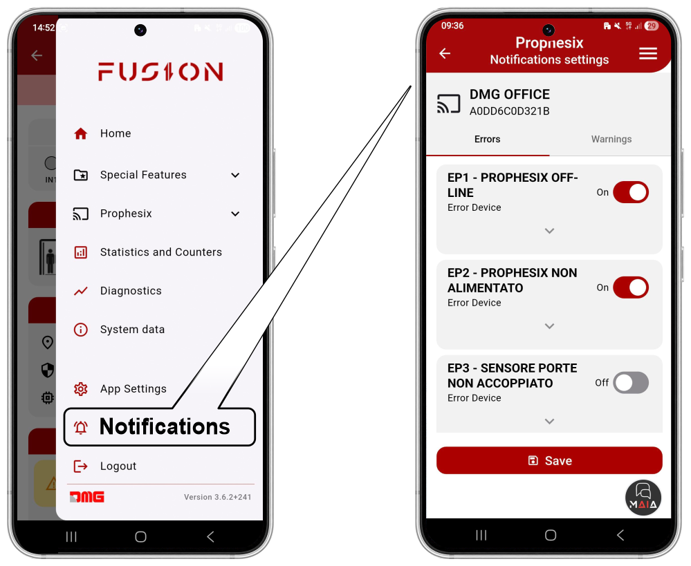
From this menu, you can configure notifications for the single Prophesix device you are connected to.
Notifications, divided into Errors and Warnings, can be enabled or disabled for each error code.
Datasheet
| Power supply: 12/24 V AC/DC |
| Integrated power backup (see note below) |
| 8 opto-isolated inputs 12/24 V AC/DC (min/max? R=?), divided into 2 independent + 6 grouped |
| 2 relay outputs: 1 A @ 24 V AC/DC |
| Temperature and humidity sensor: SHT40A |
| Digital audio-band microphone (optional) |
| Analog wide-band microphone (optional) |
| WiFi connectivity: 802.11 a/b/g/n + BLE 4.0 |
| LTE Cat1 connectivity: Simcom A7672E with onboard antenna and SMA connector for external antenna, micro SIM slot + possibility to mount on-chip eSIM |
| 6-axis sensor: ST LSM6DSOX |
| Pressure sensor: Bosch BMP390 (optional) |
| Vibration sensor: ST IIS3DWB (optional) |
| RS485 (optional): for connection to display, control panel, or other devices |
| CAN bus (optional): for connection to display, control panel, or other devices |
| 1 optional light presence sensor in the car |
| UART interface: for debug/log/firmware upload |
| MicroSD card slot: for log/debug management |
Note: BBX includes an internal power reserve (supercapacitor) to transmit input status (e.g., alarm) and blackout events within 30 seconds of power loss.
Declaration of conformity
The manufacturer, DMG S.p.A., declares that the radio equipment type PROPHESIX EBBX is in compliance with Directive 2014/53/EU – RED.
The full text of the EU Declaration of Conformity is available at the following Internet address:
https://dido.dmg.it/knowledge-base/declaration-of-conformity/#electronic-devices
Download
| Reference | Version | Link |
|---|---|---|
| Actual version | 1.0 | Download PDF (English) |