
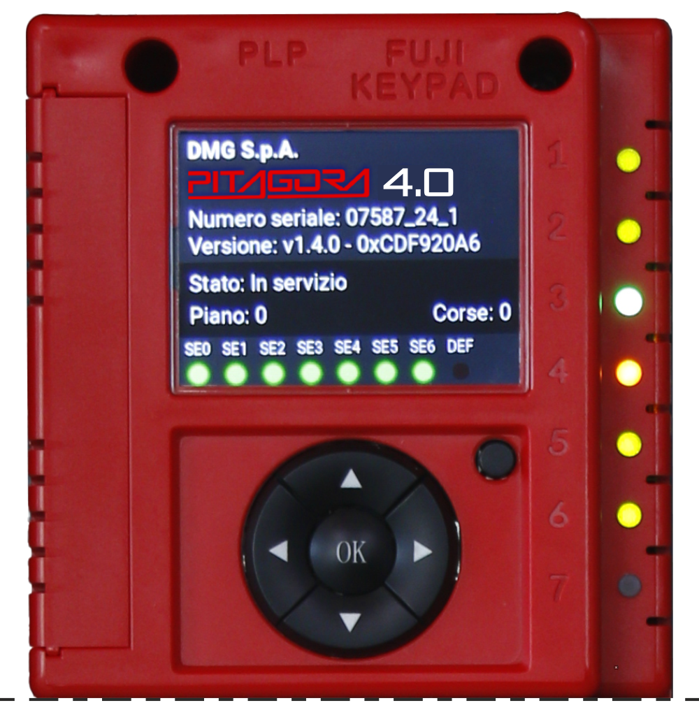
Integrated Programming Module
The Motherboard has an integrated programming module that allows viewing and editing of all the basic parameters for the controller management and configuration. In VVVF’s version, also FUJI’s parameters of the basic (menu VVVF BASE) and advanced (VVVF ADVANCED menu) configuration may be viewed and edited.
Functionality of the programming keys
 | Menu navigation keys and parameter selection keys. |
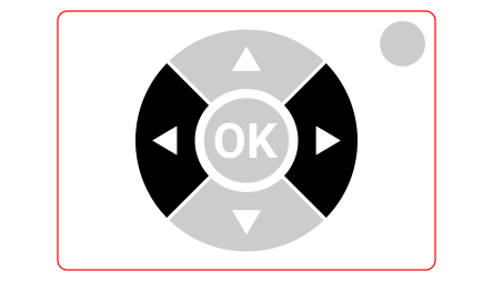 | Menu depth navigation keys (forward and backward). |
 | OK button: Key to access the selected menu and to confirm the selected parameter. ESC button: Returns one level back in the menu. |
Programming menu and Changing system parameters
Access to the programming menu
Access the ‘Emulation’ menu to configure the programming parameters.

Configuration menu
| Code | Parameter name | Parameter description |
|---|---|---|
| A1 | Temporary operations | Activation of the Temporary Operation mode of the system |
| A2 | Test & measures | Automatic tests to facilitate the final checks before the system is put in normal service |
| A3 | Acces Code ? | Definition of a passcode to access the setup Menu |
| A4 | Type of wiring | Type of wiring configuration between controller and cabin / floors |
| A5 | Type of control | Type of control for the lift and collection mode |
| A6 | Type of traction | Traction VVVF or Hydraulic lift (Direct start / soft starter / Star delta) |
| A7 | No. of floors | Number of floors of the installation |
| A8 | Re-levelling | Parameter that activates and manages the Relevelling manoeuvre (mandatory for hydraulic systems, optional for VVVF systems) |
| A9 | Main floor | Position of the main floor (all calls below this floor are served only upwards if down collective) |
| A10 | Low speed fault time | Time before activation of the Low Speed fault (Fault #3) |
| A11 | Running time: | Time before activation of running time fault #26-27 |
| A12 | Calls with 16IO board | Parameter that defines the mode of use of the 16IO terminal board in the case of terminal cabin connections: 1) 16IO A board: the 16IO board is used as the only interface board in the panel, to manage the terminal cabin calls (12 floors max) 2) 16IO B board: the 16IO board is used as the second interface board in the panel, to manage the terminal cabin calls (12 floors max) 3) 16IO A+B board: two 16IO boards are used simultaneously to manage the terminal cabin calls (28 floors max) |
| A13 | Group operation | Type of group operation (Simplex / Multiplex / Multiplex light) |
| A14 | Multiplex Configuration | Parameters for Multiplex configuration. Elevator position in the Group; Push-Buttons Line; Multiplex floors; Multiplex Offset; Long press multiplex call; |
| A15 | Multiplex Call | In multiplex installations a floor call can be differentiated with a long push-button pressure (more than 3 seconds) calling: a) The installation with lower “Lift No (LN)” parameter (for example if there is a duplex installation with a big cabin for disabled passengers and a smaller one, the greater must be set as “1” and the other as “2”; b) In an “asymmetric floor distribution” system, the installation that can reach the lowest/highest level. |
Doors menu
| Code | Parameter name | Parameter description |
|---|---|---|
| D0 | Retiring cam activation delay | Delay before activation of the retiring ramp |
| D1 | Retiring cam deactivation delay | Delay before deactivation of the retiring ramp |
| D2 | Lock fault delay | Delay before the activation of the door lock fault (Fault #9) |
| D3 | Door opening delay | Delay before auutomatic door opening (upon arrival at floor) |
| D4 | Parking time with open doors | Parking time at floors with open doors before door close command |
| D5 | Door closing delay | Delay before door closes in case of registered calls |
| D6 | Access mode | Number of accesses and door opening logic |
| D7 | Type Door A | Door type for entrance A: 1) Full automatic: cabin+floor automatic doors; 2) Car automatic: manual doors at floors, automatic cabin doors; 3) Manual: manual doors at floors, car doors manual or not present; 3) Car independent: manual doors at floors, car doors independent; |
| D8 | Door A with limit switch | Presence of a limit switch for door A (not present for manual and independent doors) |
| D9 | Access layout Side A | Access layout for Side A of the installation: access to each floor and (for automatic doors) type of parking (with doors open or closed). “NO”: permanent exclusion of the access from the total count of stops “Not enabled”: temporary exclusion of the access. |
| D10 | Door A Open/Close time | Door opening/closing operation completion time (Doors without limit switches) |
| D11 | Door A powered | Door A constantly powered during the run (door close) or at floor (door open) |
| D12 | Type Door B | Selection of door type for entrance B (see Type Door A): |
| D13 | Door B with limit switch | Presence of a limit switch for door B (not present for manual and independent doors) |
| D14 | Access layout Side B | Access layout for Side B of the installation: access to each floor and (for automatic doors) type of parking (with doors open or closed). “NO”: permanent exclusion of the access from the total count of stops “Not enabled”: temporary exclusion of the access. |
| D15 | Door B Open/Close time | Door opening/closing operation completion time (Doors without limit switches) |
| D16 | Door B powered | Door B constantly powered during the run (door close) or at floor (door open) |
| D17 | Advance opening | Early door opening (before the cabin stops) |
| D18 | Photocell type | Parameter to select the type of photocell: NO photocell: contact opens if the beam is free. The contact closes if the beam is interrupted. The shock, photocell and open door contacts must be wired in parallel. NC photocell: opposite of the NO photocell. The shock, photocell and open door contacts must be wired in series. NOTE: The shock, photocell and open door contacts must all be of the same kind (NO or NC) |
| D19 | Door contact delay | Delay before start (to compensate for any bounces from worn safety contacts) |
Signals menu
| Code | Parameter name | Parameter description |
|---|---|---|
| Delay end priority | Priority mode holding time before reactivating floor or cabin calls. If the CABIN PRIORITY function is activated (from DMCPIT card input): System waiting time, after deactivation of the function, before recording a floor call again. If the LOP PRIORITY function is activated (from BDU input): System waiting time, after deactivation of the function, before recording a cabin/floor call again. Note: in systems with UNIVERSAL operation, this parameter defines the time spent in the BUSY state. | |
| LOP feedback | Enables the blinking mode for floor buttons upon registration | |
| AUX outputs | Set up of the auxiliary outputs of the 16 RL cards (if present) and the BDUs. The settings must be made progressively, first RL-1 then RL-2 then BDU. Outputs available for the RL-1 Card: 1 wire/floor display / “Car at floor” signal / Floor light / Gray display / 9 segment display / “Car coming” signal / 1 wire/floor HYD Outputs available for the RL-2 Card: “Car at floor” signal / Floor light / Gray display / 9 segment display / “Car coming” signal Combinations of OUT-1 and OUT-2 outputs for the BDUs: Type 0 = Car at floor + Out of Service Type 1 = Up arrow + Down arrow Type 2 = Car at floor + Car coming Type 3 = Car at floor + 3 Wire Display Note: The configuration is first generic and then specific for each floor (example arrows to all floors and 3 wire display to main floor). See DIDO for details. | |
| Automatic floor designation | This parameter defines the numerical value associated with the piano assigned to the bottom of the piano (“Floor 0”). The serial display automatically indicates an incremental number at every subsequent floor. | |
| Manual floor designation | Manual setting of alphanumeric characters for serial position indicators. Setting must be done for each floor | |
| Trigger on PV | Parameter that activates the trigger for speech synthesis / next direction arrows at the slowdown point (Yes) or upon arrival at the floor (No). | |
| Next direction arrows | Parameter that activates the trigger for speech synthesis / next direction arrows at the slowdown point (Yes) or upon arrival at the floor (No). | |
| Cabin light timer | Timer for the light in the cabin after arriving at the floor. With the parameter set at 0s the timer is not active (light always on). | |
| Delay EME | Multiparameter for Automatic return to floor in emergency (See https://dido.dmg.it/it/knowledge-base/p40-emergency-operations/). Value #1: Type of automatic return: Type A = return to the nearest floor (Emergency 81.20 and 81.1 with UPS) Type B = return to the nearest floor (Integrated emergency for gearless 81.20) Type C = return to the floor defined as MAIN (Emergency 81.20 and 81.1 with UPS) Type D = specific evacuation maneuver for elevators on ships (RNO). Value 2: Delay before starting the Emergency maneuver (from IEME power failure signal). Note: in hydraulic systems the descent is always at the lowest level | |
| Buzzer 81-21 | Activation of the EN81.20 acoustic signal (door bypass) also to indicate the presence of inactive 81.21 protections in systems with reduced pit/headroom. | |
| Ship Functions | Enabling of special functions dedicated to elevators installed on cruise ships. | |
| Beep at stop | Enables a beep warning signal in the cabin keypad when the elevator arrives at the floor. |
Special features menu
| Code | Parameter name | Parameter description |
|---|---|---|
| Reset Direction | Direction of travel during the reset procedure | |
| Traveling limits in inspection | (Only for magnetic readers positioning system) Defines the travelling limits during inspection mode. If set on “Beyond AGB/AGH”, the controller does not allow any movement beyond top/bottom floors. | |
| Fire-fighters Operations | For lifts that include the Fire-Fighter Operation, this multiple parameter defines the type of fire fire operation and the related settings for each floor (recall side, type of POM and CPOM key contacts). | |
| Fire detection | Parameter for fire detection at floors. if the lift is at a different floor than the one where fire was detected, all registered calls from/to this floor are cancelled; if the lift is at the floor where fire was detected, the controller blocks door opening, closes doors (if open upon fire detection) and sends the car to a safe floor | |
| Stop button registration | The system registers the out of service mode (pressure of STOP button). It is also possible to set the delay to avoid simultaneous movement in installations powered with a generator. | |
| EN 81-20 | Parameter that configures the system according to the EN 81-20 standard. If set to “YES” the following are enabled: the inspection button panel from the bottom of the pit; the access control in the pit; the control of the presence of the UCM; the monitor of the second contact of the cabin doors; the door photocell with NC (normally closed) contact | |
| Anti-nuisance option | Option that limits unauthorized activations. The value defines the maximum number of stops without cutting the photocell (for automatic doors) or opening the door (manual) beyond which all calls from the cabin are cancelled | |
| Out of Service floor | Destination floor for Lift out of service (HS input activated). | |
| Automatic return to floor | Multiple parameter for the Automatic Return to Floor manouever. Defines the return flow and the minimum waiting time before activation of the automatic return | |
| Return zones | Advanced settings for return at floor at planned hours / days: -) Day (0 = everyday, 1 = monday … 7 = sunday); -) Selected time interval (4 interval each day); -) Return floor; -) Start time; -) End time (max time: 7h 45 min); | |
| R. zone timing | Timing for selected return zones | |
| Call erasing at floor | Cancellation of calls to the floor where the cabin stops, without checking the direction of travel (option valid only for full collective operation) | |
| Drift control (France) | Drift control (NF P82-212) | |
| Cabin call access code / Penthouse | Allows you to define a 4-digit code to enable a cabin call. This option can be enabled for every floor, identified by the labels BC0…BC27. See the “Access Protection” page on DIDO for operating details. Note: Entering the code “0 _ _ _ ” enables the PentHouse function for that floor. | |
| Machine room temperature check | Enables the control of the ambient temperature in the machine room through the relative sensor (if present). If the temperature goes outside the minimum and maximum thresholds set for a time greater than 30 seconds, the system stops at a floor and error 39 “”Ambient temperature”” appears. In addition to setting the two thresholds, it is necessary to set the ambient temperature, confirming or modifying the one detected. Note: The control is active only in normal operation or Cabin priority. | |
| Automatic Calls | Enables an automatic test mode that simulates up to 120 calls at programmable intervals between 10 s and 60 s. It is also possible to enable or disable the door opening (if enabled, the system will also accept floor calls while still simulating scheduled calls). The function is automatically terminated when the system is turned off and/or the system is put in Inspection mode | |
| Monitor UCM | UCMP Management Solution | |
| UCM | Installation type 81-1 / 81-20 / 81-21 Shaft access procedure and Protections. | |
| Forced Stop | Parameter that defines a floor as forced. If activated, the system will stop at that floor at each passage. | |
| Protected floor | Parameter that defines a floor as protected in combination with the “Live+” function. Upon arrival at the protected floor, the doors open only with explicit consent (pressing the door opener button), otherwise the system returns to the previous floor. | |
| LOP Priority | Enables the floor priority call function. Needs the Pitagora 16 I/O card (or keyswitch input from floor BDU) | |
| Enable floor | Call enabling function (e.g. CARD Reader). Requires the auxiliary 16 I/O card. Type 1: LOP enable: to enable calls, the corresponding input of the 16 I/O card must be closed. Type 2: COP enabling To enable calls, the corresponding input of the 16 I/O card must be closed Type 3: Enable COP + LOP: to enable calls, the corresponding input of the 16 I/O card must be closed (disabling the floor) | |
| Shaft Protection | Enables the shaft access protection circuit (EN81-20) | |
| Integrated Load Weighing | Enable the built-in load weighing function. Requires a calibration procedure (Test 22) |
Positioning menu
– With encoder –
| Code | Parameter name | Parameter description |
|---|---|---|
| Positioning system | Type of positioning system: with Encoder or traditional. Note: Can only be modified in Temporary Oper. Mode | |
| Autosetting | Start of floor position self-learning procedure. Can only be modified in Temporary Operation mode. | |
| Floor Position | Position value for each floor | |
| Accel. Time | Acceleration time. Time required to switch from start speed to travelling speed. | |
| Starting Boost | Starting speed | |
| Stopping Boost | Final (stopping) speed | |
| Max speed | Maximum speed during the travel | |
| Inspection Speed | Travelling speed in inspection mode | |
| AGB/AGH speed | Travelling speed on AGB/AGH limit points. Same speed adopted during emergency operations | |
| Delay Dir.-BRK | VVVF: Delay between activation of travel direction and BRK command (start) OLEO: Star / Delta delay | |
| Delay BRK-S | Delay between activation of BRK command and beginning of the analogic speed ramp | |
| Delay BRK-Dir. | Delay between deactivation of run command and deactivation of travelling direction (stop at floor) | |
| Emergency BRK ON | Emergency break modulation parameter | |
| Emergency BRK OFF | Emergency break modulation parameter | |
| Monitor Encoder | Contains information on: Encoder features, reading of slowdown heights (R1D / R1S), re-levelling (RRIPD / RRIPS) and stop of the cabin (RLD / RLS) where D indicates down while S means up; finally it contains info on reading AGB / AGH and ZP heights. Note: R1D and R1S heights can be modified pushing Enter without repeating self learning procedure (to let the slowing down distance be equal in rise and descent). | |
| ZP lenght |
– With magnetic readers –
| Code | Parameter name | Parameter description |
|---|---|---|
| Positioning system | Type of positioning system: with Encoder or traditional. Can only be modified in Temporary Oper. Mode Note: in case of absolute Encoder and shaft lengths longer than 65 meters change the resolution of Encoder = 2 in autosetting menu before starts the Manual teach procedure. | |
| Top PV | Position of the deceleration (passage in Low Speed) and number of entrances | |
| PV at floors | Position of the specific deceleration for each floor | |
| Short level delay | Time before short level deceleration (only if a short level is programmed) | |
| Delay Top PV 2 | Delay before passage to Intermediate speed | |
| Delay Dir.-BRK | VVVF: Delay between activation of travel direction and run command (BRK) OLEO: Star / Delta delay | |
| Delay BRK-S | Delay between activation of BRK command and speed command | |
| Delay BRK-Dir. | Delay between deactivation of run command and deactivation of travel direction (arrive at floor) | |
| Inspection speed | Sets the speed of travel in inspection | |
| Emergency BRK On | Emergency break modulation parameter (modify only if EME board is not present) | |
| Emergency BRK Off | Emergency break modulation parameter (modify only if EME board is not present) |
VVVF Basic menu
| Code | Parameter name | Parameter description |
|---|---|---|
| F03 | Maximum speed | Max speed of the motor |
| F05 | Rated Voltage | Rated voltage of the motor driven by the inverter |
| F07 | Acc T1 | Acceleration ramp (Only with FAI/FAS positioning system) |
| F08 | Dec T2 | Acceleration ramp (Only with FAI/FAS positioning system) |
| F42 | Control Mode | Control Mode |
| E12 | Acc/dec Time 5 | |
| E13 | Acc/dec Time 6 | |
| E15 | Acc/dec Time 8 | |
| E16 | Acc/dec Time 9 | |
| C07 | Creep Speed | Creeping speed (Only with FAI/FAS positioning system) |
| C10 | Middle Speed | System speed under inspection mode (Only with FAI/FAS positioning system) |
| C11 | High Speed | High speed for multistep speed change (Only with FAI/FAS positioning system) |
| P01 | Motor Poles | Number of poles of the motor |
| P02 | Motor Rated Cap | Rated power of the motor |
| P03 | Motor Rated Cur | Rated current intensity of the motor |
| P04 | Motor Autotuning | Auto tuning of motor parameters (geared drives only) |
| P06 | M-No-Load Curr. | Motor no-load current |
| P12 | M-Rated Slip | Rated slip frequency of the motor |
| L01 | PG select | |
| L02 | PG resolution | Resolution of the pulse encoder (Pulse/ Turn) |
| L19 | S-Curve 1 | S-Curve – 1 |
| L24 | S-Curve 6 | S-Curve – 6 |
| L25 | S-Curve 7 | S-Curve – 7 |
| L26 | S-Curve 8 | S-Curve – 8 |
| L27 | S-Curve 9 | S-Curve – 9 |
| L82 | Brake On Delay | Delay from activation of BRKS output |
| L83 | Brake Off delay | Delay from deactivation of BRKS output |
VVVF Advanced menu
| Code | Parameter name | Parameter description |
|---|---|---|
| F01 | Speed command | Command selection for speed variation |
| F03 | Maximum speed | Max speed of the motor |
| F04 | Rated speed | Rated speed of the motor (Frequency) |
| F05 | Rated Voltage | Rated voltage of the motor driven by the inverter |
| F07 | Acc T1 | Acceleration ramp (Only with FAI/FAS positioning system) |
| F08 | Dec T2 | Acceleration ramp (Only with FAI/FAS positioning system) |
| F09 | TRQ Boost | Torque increase |
| F10 | Electronic OL | Overload electrical protection |
| F11 | Overload Level | Electronic Thermal Overload Protection for Motor (Value in Ampere equal to the inverter size) |
| F12 | Overload time | Thermic time constant |
| F20 | DCBrake speed | Frequency threshold for DC INJECTION |
| F21 | DC Brake level | Intensity threshold for DC INJECTION |
| F22 | DC Brake T | DC INJECTION time |
| F23 | Starting Speed | Starting speed (in Hz) for the inverter |
| F24 | Holding Time | Holding time of running at starting speed for the inverter |
| F25 | Stopping Speed | Stopping speed (in Hz) for the inverter |
| F26 | Motor Sound | Carrier frequency |
| F42 | Control Mode | Control Mode |
| F44 | Current Limiter | Activation level of the current limiter. % to the rated current of the inverter. If “Auto”, value means no current limitation |
| E04 | Command X4 | Input X4 not used |
| E05 | Command X5 | Input X5 not used |
| E06 | Command X6 | Input X6 not used |
| E07 | Command X7 | Input X7 not used |
| E08 | Command X8 | Input X8 not used |
| E10 | Acc/dec Time 3 | |
| E11 | Acc/dec Time 4 | |
| E12 | Acc/dec Time 5 | |
| E13 | Acc/dec Time 6 | |
| E14 | Acc/dec Time 7 | |
| E15 | Acc/dec Time 8 | |
| E16 | Acc/dec Time 9 | |
| E20 | Signal Y1 | Output Y1 (transistor) not used |
| E21 | Signal Y2 | Output Y2 (transistor) not used |
| E22 | Signal Y3 | Output Y3 (transistor) not used |
| E23 | Signal Y4 | Output Y4 (transistor) not used |
| E30 | Speed Arr. Hyst | Not used |
| E31 | Speed Det.Lev | Not used |
| E32 | Speed Det Hyst | Not used |
| E39 | RRD Level | Recommended direction in emergency (Not used) |
| E61 | Analog Input 12 | Function of analog input 12 |
| E98 | Command FWD | Function for screw terminal FWD |
| E99 | Command REV | Function for screw terminal REV |
| C01 | BATRY TL i | “Torque limitation in emergency. If “OFF”, value means no current limitation” |
| C02 | BATRY TL t | |
| C03 | Battery Speed | Speed during emergency run |
| C07 | Creep Speed | Creeping speed (Only with FAI/FAS positioning system) |
| C10 | Middle Speed | System speed under inspection mode (Only with FAI/FAS positioning system) |
| C11 | High Speed | High speed for multistep speed change (Only with FAI/FAS positioning system) |
| P01 | Motor Poles | Number of poles of the motor |
| P02 | Motor Rated Cap | Rated power of the motor |
| P03 | Motor Rated Cur | Rated current intensity of the motor |
| P04 | Motor Autotuning | Auto tuning of motor parameters (geared drives only) |
| P06 | M-No-Load Curr. | Motor no-load current |
| P07 | M-%R1 | Motor (%R1) |
| P08 | M-%X | Motor (%X) |
| P09 | M-Slip driving | Slip compensation gain in percentage to the rated slip (P12) at the driving sides |
| P10 | M-Slip braking | Slip compensation gain in percentage to the rated slip (P12) at the braking sides |
| P11 | M-Slip T | Slip compensation time value (fixed) |
| P12 | M-Rated Slip | Rated slip frequency of the motor |
| P60 | Armature Resistance – Rs | |
| P62 | Armature q-axis reactance – Xs | |
| P63 | Interphase Inductive Voltage – E | |
| P65 | q-axis inductance magnetic saturation correction | |
| H04 | Auto reset Times | Auto-resetting (Number of times) |
| H05 | Auto reset int | Auto-resetting (Reset interval) |
| H06 | Cooling Fan CTRL | “Delay on Cooling Fan turning off (Auto value means that there is no limit on fan control; fan is always turned on)” |
| H56 | ||
| H57 | S-Curve 11 | Curve to S-11 |
| H58 | S-Curve 12 | Curve to S-12 |
| H64 | Zero Hold Time | |
| H65 | Soft Start Time | |
| H67 | Stop Hold Time | |
| H96 | Brake Monitor | Enable Brake monitor |
| H190 | Motor UVW order | Sequenza fasi uscita motore |
| L01 | PG select | |
| L02 | PG resolution | Resolution of the pulse encoder (Pulse/ Turn) |
| L03 | P.P.Tuning | |
| L04 | P.P.Offset | Magnetic Pole Position Offset (Offset angle) for gearless drives |
| L05 | ACR P gain | |
| L07 | Automatic pole tuning selection | |
| L19 | S-Curve 1 | S-Curve – 1 |
| L20 | S-Curve 2 | S-Curve – 2 |
| L21 | S-Curve 3 | S-Curve – 3 |
| L22 | S-Curve 4 | S-Curve – 4 |
| L23 | S-Curve 5 | S-Curve – 5 |
| L24 | S-Curve 6 | S-Curve – 6 |
| L25 | S-Curve 7 | S-Curve – 7 |
| L26 | S-Curve 8 | S-Curve – 8 |
| L27 | S-Curve 9 | S-Curve – 9 |
| L28 | S-Curve 10 | |
| L29 | SFO Hold T | “Short Floor Operation (Holding time) Only used for FAI-FAS positioning mode” |
| L30 | SFO Speed | Short Floor Operation (Allowable speed) – NOT USED |
| L36 | ASR P Gain High | |
| L37 | ASR I Gain High | |
| L38 | ASR P Gain Low | |
| L39 | ASR I Gain Low | |
| L40 | Switch Speed 1 | Not used |
| L41 | Switch Speed 2 | Not used |
| L42 | ASR-FF Gain | |
| L55 | TB Start time | |
| L56 | TB End time | |
| L64 | TB Digital 3 | |
| L65 | ULC operation | Unbalanced load Compensation |
| L66 | ULC activation | Unbalanced load compensation (Activation time) |
| L68 | ULC ASR P gain | |
| L69 | ULC ASR I gain | |
| L73 | APR P gain zero | |
| L74 | APR D Gain | |
| L75 | Filter Time | |
| L76 | ACR P constant | |
| L80 | Brake mode | Brake Control (BRKS) output mode |
| L81 | Brake On Level | Output current that turns the BRKS signal ON when L80 = 2. |
| L82 | Brake On Delay | Delay from activation of BRKS output |
| L83 | Brake Off delay | Delay from deactivation of BRKS output |
| L84 | BRKS check t | Allowable time between BRKS output and BRKE input (Er6) |
| L99 | ACTION SEL | Not used |
| L122 | Del. Op. Input Power Det. Level | |
| L124 | Del. Op. Dir. Calc. Delay Timer | |
| L130 | Sheave diameter (Ds) | |
| L131 | Encoder diameter (De) | |
| L132 | Theta compensation band | |
| L133 | Theta compensation gain lower limiter | |
| L134 | Backlash Time | “Backlash Time (When L65 = 2)” |
| L198 | Op. set switch 1 | BIT0 = It is possible to fix the carrier frequency to 16 kHz for the whole speed range in order to reduce driving noise. |
| L199 | Op. set switch 2 | Reserved |